The training report details a 23-week industrial training program at Colombo Dockyard PLC undertaken by W.A.C.S. Muthukumarana from August 1 to December 31, 2016. It includes an introduction to the company, a SWOT analysis, and comprehensive descriptions of various training locations, projects, and gained experiences. The report concludes with reflections on the overall usefulness and drawbacks of the training experience.


![Annex 6 (Continued)
xxxiii
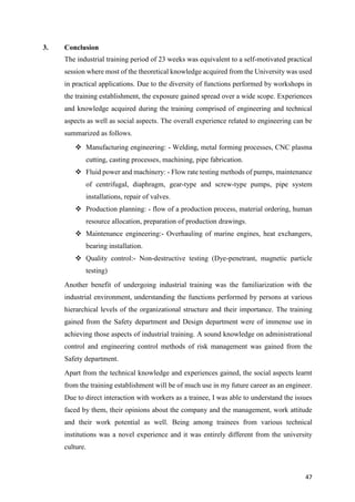
1. Determination of maximum cable tension
By taking moments about the hinge,
2T x LSin α –Mg x
L
2
𝐶𝑜𝑠 𝜃 = 0
Where T=Cable tension, M= Mass of the ramp
Considering the trigonometric relationships, α and θ are related as mentioned below.
Tan(𝛼 + 𝜃) =
ℎ + 𝐿𝑠𝑖𝑛𝜃
𝐿𝐶𝑜𝑠𝜃
𝛼 = Tan−1
[
ℎ + 𝐿𝑠𝑖𝑛𝜃
𝐿𝐶𝑜𝑠𝜃
] −𝜃
Where h= height of the supporting pole, L= Length of the ramp.
Figure 1.1 Forces acting on the ramp while lifting/lowering
T=
Mg Cosθ
4𝑆𝑖𝑛𝛼](https://image.slidesharecdn.com/cc11650e-890c-4882-acfc-3fcbd7045402-170206060538/85/Industrial-training-report-84-320.jpg)
![Annex 6 (Continued)
xxxiv
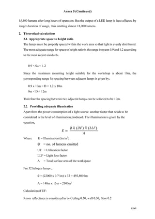
From the equations derived, the inclination of the ramp at which the cable tension becomes a
maximum can be determined from a graph.
From the graph it is clear that Tension is maximum at θ = 45⁰.
Determination of maximum tension
Details:- h=2m (Can be varied), L=2m (fixed value), M=300kg (fixed value)
𝛼 = Tan−1
[
2 + 2𝑠𝑖𝑛 45°
2𝐶𝑜𝑠 45⁰
] −45⁰
𝛼 = 22.5⁰
T=
Mg Cosθ
4𝑆𝑖𝑛𝛼
=
(300𝑘𝑔)(9.81𝑚𝑠−2) cos 45⁰
4 𝑠𝑖𝑛22.5°
T = 1359.5 N
Tmax ≈ 1360 N](https://image.slidesharecdn.com/cc11650e-890c-4882-acfc-3fcbd7045402-170206060538/85/Industrial-training-report-85-320.jpg)

![Annex 6 (Continued)
xxxvi
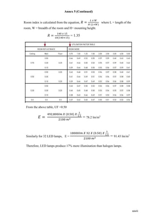
Figure 2.2 Graph of ramp inclination vs. pulley force
The above graph has been plotted for all real values of ramp inclination θ within the range -180⁰
to +180⁰. But in this application, θ ranges between -45⁰ and +45⁰; anti-clockwise direction being
considered as positive. From figure 2.2, and figure 2.3 the highest resultant force occurs at -45⁰ for
the above specified range. For the pulley arrangement shown in figure 2.3, tension along the cable
can be calculated from below equations.
T1= 1360 N T4 = T3 𝑒 𝜇
𝜋
2
T2 = T1 𝑒 𝜇𝛼
T5 = T4 𝑒 𝜇𝛼
T3 = T2 𝑒 𝜇
𝜋
2 T6 = T5 𝑒
𝜇[𝛼+
𝜋
2
]](https://image.slidesharecdn.com/cc11650e-890c-4882-acfc-3fcbd7045402-170206060538/85/Industrial-training-report-87-320.jpg)