Downloaded 22 times
![1 XC = = XL= 2πfL. (11.7)
2πfC
Rearranging,
f = 1 / (2π LC ) (11.8)
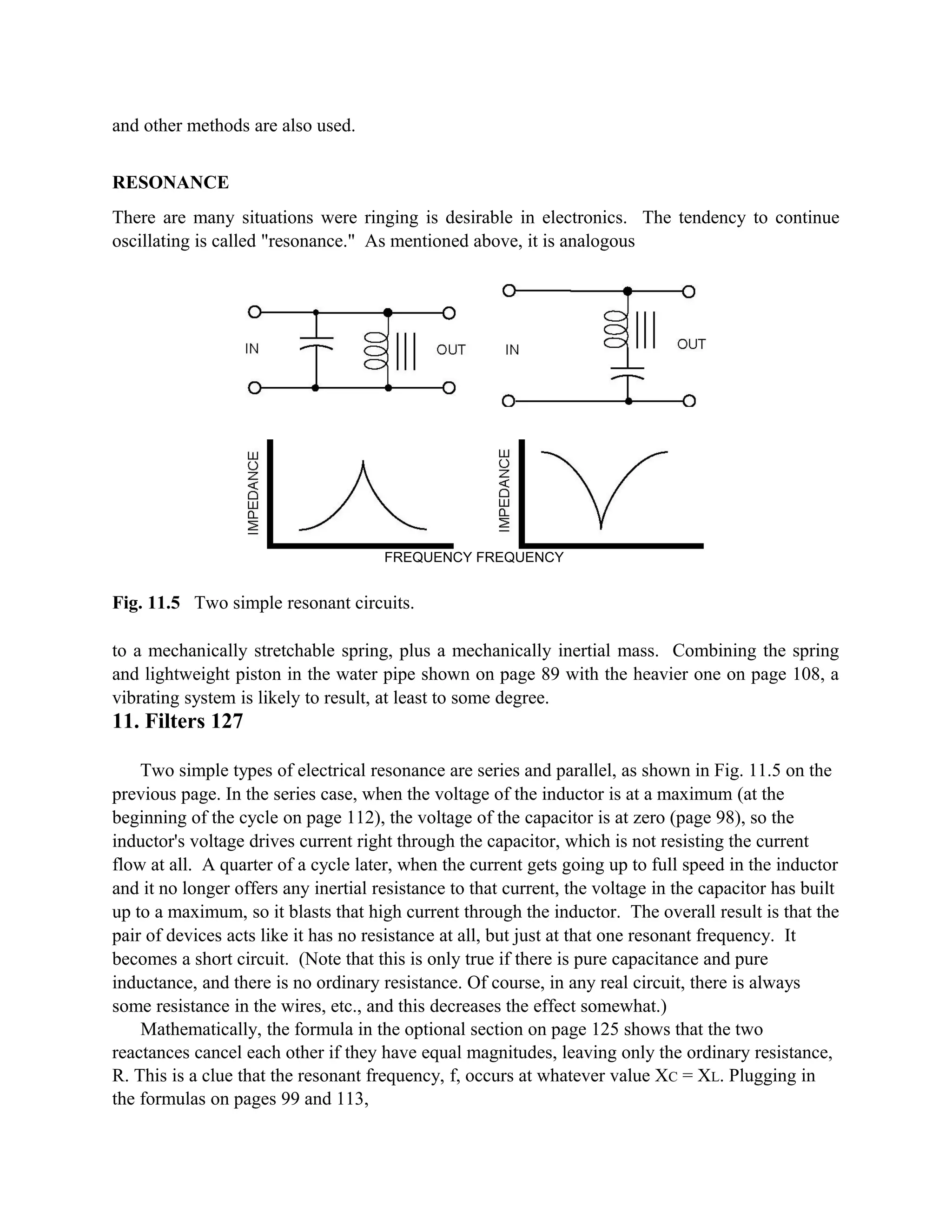
In the parallel case of Fig. 11.5, the impedance (effective overall resistance to ac voltage) is
a maximum at that same resonant frequency, and if a wave of that frequency were coming along
in the wires, it would not be short circuited. If there was no ordinary resistance in the wires, that
wave would start an oscillation, going back and forth within the square that makes up the parallel
circuit, and it could continue for a long time. (Note, however, that it has to be started by
something else.) It would reach its peak voltage at the same instant that the wave coming in
from the left reaches its peak. Therefore, as electronic engineers say, "it would look like an
infinite resistance" to the incoming wave. (The square that makes up a parallel "resonator" like
this is cometimes called a "tank circuit.")
COMMENT Resonant circuits are often used as filters. The parallel type can be used to short
out everything except one particular frequency, and it is often used this way in radio receivers
and transmitters. In the series type, if the inductor is the
128 11. Filters
primary coil of a transformer, then only one frequency will come out of the secondary coil
(not shown in the figure).
The more energy that is lost through heat, via the electrical resistance, the sooner the
oscillation will die out — also, the less sharply the oscillation will be "tuned" to one narrow
frequency. By comparison, lower resistance provides sharper tuning — higher Q (or "quality
factor," as mentioned on page 101).
EXPERIMENTS, PART 2
Parallel LC Resonator
The experimenter can assemble the circuit shown at the upper left of Fig. 11.5. The 1,000 mfd
capacitor is used, and the "12 volt" secondary of the transformer is the inductor, using just one
yellow wire and the center-tapped black wire.
Then attach the vertical input of the oscilloscope to the resonator output. The scope can be
set as on page 122, except that the TRIGGER SOURCE should be VERT, and the TIME/DIV
should be 0.1 s (a tenth of a second per square division on the screen). The channel 2 (Y)
sensitivity can be about 2 V/DIV. Place the bright spot (or line) in the middle of the screen,
using POSITION [Y].
A nine volt battery (not shown in the diagram) is momentarily attached to the resonator input.
On the scope, a bouncing sort of action is observed, in which the bright spot flies upward and
then down, but it goes down past the middle of the screen and then is damped back up to the
middle again. (The current flow in the inductor has continued to push the voltage down below
zero, becoming negative.)](https://image.slidesharecdn.com/filtersandresonance-130711083542-phpapp01/75/Filters-and-resonance-11-2048.jpg)

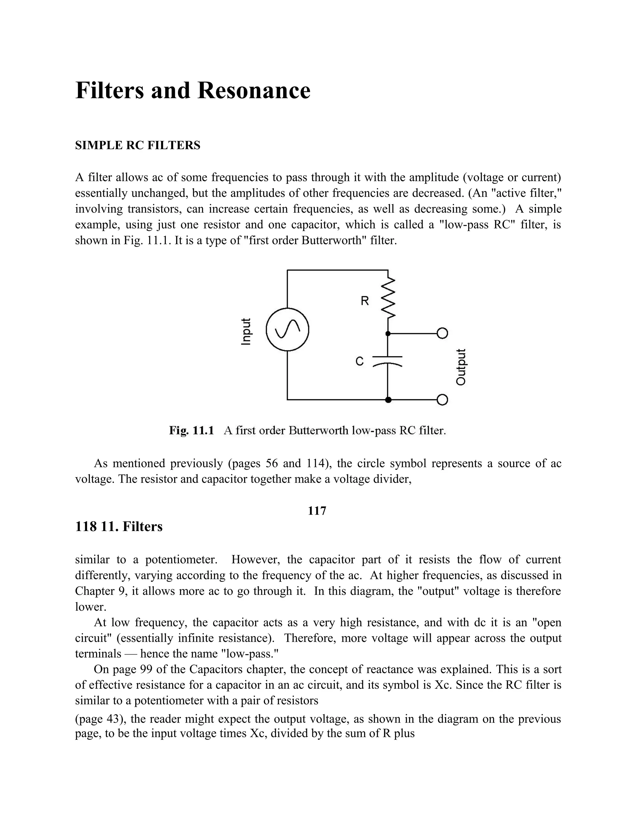
This document discusses simple RC filters and how they work to filter different frequencies. A basic RC filter circuit uses one resistor and one capacitor. At low frequencies, the capacitor acts like an open circuit and more voltage passes through. As frequency increases, the capacitor's reactance decreases and it blocks more voltage. The output voltage of an RC filter depends on the input voltage, capacitive reactance, and total impedance. A graph shows the frequency response curve of an RC filter, with output decreasing as frequency increases above the corner frequency, where resistive and reactive components are equal.


