SlideShare a Scribd company logo
1 of 48
Cylindrical
Capacitor
• Basic Structure: A cylindrical capacitor comprises two
coaxial cylinders, typically an inner and an outer cylinder,
aligned along the same axis.
• Dielectric Medium: It involves an insulating material, the
dielectric, placed between the cylinders to prevent direct
electrical contact. This dielectric can vary from air to specific
non-conductive substances.
• Capacitance Factors: The capacitance of a cylindrical
capacitor depends on the radii of the cylinders, their lengths,
and the permittivity of the dielectric material. Formulas exist
to calculate capacitance based on these parameters.
• Applications: Cylindrical capacitors are used widely in
electronics, power systems, and telecommunications. They're
valued for their relatively high capacitance compared to
other capacitor designs.
• Practical Use: They serve various functions, including
energy storage, signal processing in circuits, filtering, and
regulation of electrical energy in power transmission systems.
1. A single-core cable or cylindrical capacitor consisting
two co-axial cylinders of radii a and b metre.
2. Let the charge per metre length of the cable on the
outer surface of the inner cylinder be + Q coulomb
and on the inner surface of the outer cylinder be −Q
coulomb.
3. Let εr be the relative permittivity of the medium
between the two cylinders. The outer cylinder is
earthed.
4. let us find the value of electric intensity at any point
distant x metres from the axis of the inner cylinder.
5. Total flux coming out radially from the curved surface
of this imaginary cylinder is Q coulomb. Area of the
curved surface = 2 π x × 1 = 2 π x m2 .
Potential Gradient in a Cylindrical Capacitor
Capacitance Between
Two Parallel Wires
• This case is of practical importance in overhead
transmission lines. The simplest system is 2-wire system (either
d.c. or a.c.). In the case of a.c. system, if the transmission line
is long and voltage high, the charging current drawn by the line
due to the capacitance between conductors is appreciable and
affects its performance considerably.
• let d = distance between centres of the wires A and B
• r = radius of each wire (≤d)
• Q = charge in coulomb/metre of each wire
• Now, let us consider electric intensity at any point P
between conductors A and B. Electric intensity at P* due to
charge + Q coulomb/metre on A is
Capacitors
in Series
1. C1 , C2 , C3 = Capacitances
of three capacitors
2. V1 , V2 , V3 = p.ds. across
three capacitors.
3. V = applied voltage across
combination
4. C = combined or equivalent
or joining capacitance.
In series combination, charge on
all capacitors is the same but
p.d. across each is different.
Capacitors in
Parallel
In this case, p.d. across each is the
same but charge on each is different.
∴ Q = Q1 + Q2 + Q3 or CV = C1V + C2V
+ C3V or C = C1 + C2 + C3 For such a
combination, dV/dt is the same for all
capacitors.
Cylindrical Capacitor with Compound
Dielectric
Insulation
Resistance of a
Cable Capacitor
• Current Flow in Cable Capacitor: Current primarily flows along the axis of the
core in a cable capacitor, serving its intended purpose.
• Leakage of Current: However, some current inevitably leaks, and this leakage
occurs radially, perpendicular to the intended current flow.
• Insulation Resistance: The resistance presented to this radial leakage current
is termed as the insulation resistance of the cable.
• Relation to Cable Length: With longer cable lengths, there's an increase in
leakage due to the radial current flow, resulting in reduced insulation
resistance. In essence, as cable length grows, more current leaks, leading to a
decrease in insulation resistance.
• Inverse Proportionality: The relationship between insulation resistance and
cable length is inversely proportional. Longer cables exhibit lower insulation
resistance due to increased leakage.
• Differentiation from Conductor Resistance: It's crucial not to confuse
insulation resistance with conductor resistance. Insulation resistance pertains
to the resistance against radial leakage and varies with cable length, whereas
conductor resistance, related to the conductor material, is directly
proportional to the cable length.
Energy Stored in a
Capacitor
• Initial Energy Expenditure: Charging a capacitor requires
energy from an external source. This energy is stored within
the electrostatic field that forms in the dielectric medium.
• Energy Storage and Discharge: The energy expended during
charging gets stored in the electrostatic field. Upon
discharge, this stored energy is released as the field
collapses.
• Work During Charging: Initially, when the capacitor is
uncharged, minimal work is needed to transfer charge
between the plates. However, as more charge is added,
overcoming the repulsive force between the accumulated
charges demands additional work.
• Calculation of Energy Spent: The energy spent in charging a
capacitor of capacitance C to a voltage V can be determined.
At any point during charging, if the potential difference
across the plates is v and the next charge increment
transferred is 'dq', the work done is involved in moving 'dq'
charge from one plate to the other.
Force of Attraction Between Oppositely-
charged Plates
1. Two parallel conducting plates A and B carrying
constant charges of + Q and −Q coulombs
respectively. Let the force of attraction between the
two be F newtons. If one of the plates is pulled apart
by distance dx,
then work done is = F × dx joules ...(i)
2. Since the plate charges remain constant, no
electrical energy comes into the arrangement during
the movement dx.
3. ∴ Work done = change in stored energy
Tutorial-5.2
Current-Voltage Relationships in a Capacitor
Time Constant
Discharging of a Capacitor
• when S is shifted to b, C is discharged through R. It will be seen that
the discharging current flows in a direction opposite to that the
charging current.
• Hence, if the direction of the charging current is taken positive, then
that of the discharging current will be taken as negative. To begin
with, the discharge current is maximum but then decreases
exponentially till it ceases when capacitor is fully discharged.
Transient Relations During Capacitor Charging Cycle
1. Steady-State Transition: When a circuit moves from one stable state to another, it goes
through a transient state. This transient state is brief compared to the overall duration.
2. Initial and Final Conditions: The initial state is the starting stable condition, and the final
state is the target stable condition of the circuit.
3. Transient Phase: The transient state occurs between the initial and final conditions. It
represents the period during which changes in current and voltage occur in the circuit.
4. Example with RC Circuit: Consider an RC circuit where initially, the switch isn't
connected (at neither a nor b). This is the initial steady state with no current flow and
consequently no voltage drops across components.
5. Switch Position Change: When the switch moves to position a, current flows through
resistor R, initiating changes in voltage across R and the capacitor C. During this phase,
transient voltages develop until they reach their stable, final values.
6. Duration of Transient Condition: The time frame in which current and voltage variations
occur and stabilize is termed as the transient condition in the circuit.
In essence, this process describes how a circuit, such as an RC circuit, undergoes changes in
current and voltage as it transitions from an initial stable state to a final stable state, passing
through a brief transient state in between.
Transient Relations During Capacitor Discharging Cycle
Charging and Discharging of a capacitor with Initial Charge
• Initial Capacitor Potential: In this scenario, the capacitor starts with an
initial potential (Vo) that is lower than the applied battery voltage (V).
• Opposition to Applied Voltage: The initial potential (Vo) acts in opposition
to the battery voltage (V) during the charging process.
• Effect on Rate of Rise: illustrates that the initial rate of rise of the capacitor
voltage (vc ) is somewhat slower when the capacitor begins with an initial
potential (V) compared to when it starts uncharged.
• Rise from V to Final V: The capacitor's voltage rises from the initial value
(V0 ) to the final value (V) over one time constant.
• Calculation of Initial Rate of Rise: The initial rate of rise of the capacitor
voltage (vc ) from an initial value of V0 to the final value of V in one time
constant can be determined based on the specific circuit characteristics
and the relationship between the initial and final voltages.
Thank You and
Subscribe the channel &
Like the video

More Related Content

Similar to Chapter 5 B L Theraja Cylindrical Capacitor.pptx

General Physics- Electricity
General Physics- ElectricityGeneral Physics- Electricity
General Physics- ElectricitySaraLQ2
 
Capacitance and capacitor
Capacitance and capacitorCapacitance and capacitor
Capacitance and capacitorTouqeer Jumani
 
3.3 Capacitors.ppt
3.3 Capacitors.ppt3.3 Capacitors.ppt
3.3 Capacitors.pptAninDeb
 
CAPACITORS AND CAPACITANCE
CAPACITORS AND CAPACITANCECAPACITORS AND CAPACITANCE
CAPACITORS AND CAPACITANCESheeba vinilan
 
Power Circuits and Transforers-Unit 3 Labvolt Student Manual
Power Circuits and Transforers-Unit 3 Labvolt Student ManualPower Circuits and Transforers-Unit 3 Labvolt Student Manual
Power Circuits and Transforers-Unit 3 Labvolt Student Manualphase3-120A
 
Keyur be capacitors
Keyur be capacitorsKeyur be capacitors
Keyur be capacitorsKeyur Patel
 
Generation of High D.C. Voltage (HVDC generation)
Generation of High D.C. Voltage (HVDC generation)Generation of High D.C. Voltage (HVDC generation)
Generation of High D.C. Voltage (HVDC generation)RP6997
 
Chapter_18_sec_1__Electric_Potential_and_Capacitance.ppt
Chapter_18_sec_1__Electric_Potential_and_Capacitance.pptChapter_18_sec_1__Electric_Potential_and_Capacitance.ppt
Chapter_18_sec_1__Electric_Potential_and_Capacitance.pptAmitKumarLal5
 
Mechanism of-a-capacitor
Mechanism of-a-capacitorMechanism of-a-capacitor
Mechanism of-a-capacitorMasud Parvaze
 
TRANSMISSION LINES and capacity.pdf
TRANSMISSION LINES and capacity.pdfTRANSMISSION LINES and capacity.pdf
TRANSMISSION LINES and capacity.pdfpramod719257
 
Wk 10 p1 8-18.1-18.2_capacitance
Wk 10 p1 8-18.1-18.2_capacitanceWk 10 p1 8-18.1-18.2_capacitance
Wk 10 p1 8-18.1-18.2_capacitancechris lembalemba
 

Similar to Chapter 5 B L Theraja Cylindrical Capacitor.pptx (20)

General Physics- Electricity
General Physics- ElectricityGeneral Physics- Electricity
General Physics- Electricity
 
Capacitance and capacitor
Capacitance and capacitorCapacitance and capacitor
Capacitance and capacitor
 
H06 elo c
H06 elo cH06 elo c
H06 elo c
 
3.3 Capacitors.ppt
3.3 Capacitors.ppt3.3 Capacitors.ppt
3.3 Capacitors.ppt
 
MARX Generator.pptx
MARX Generator.pptxMARX Generator.pptx
MARX Generator.pptx
 
internet.pptx
internet.pptxinternet.pptx
internet.pptx
 
CAPACITORS AND CAPACITANCE
CAPACITORS AND CAPACITANCECAPACITORS AND CAPACITANCE
CAPACITORS AND CAPACITANCE
 
Power Circuits and Transforers-Unit 3 Labvolt Student Manual
Power Circuits and Transforers-Unit 3 Labvolt Student ManualPower Circuits and Transforers-Unit 3 Labvolt Student Manual
Power Circuits and Transforers-Unit 3 Labvolt Student Manual
 
Keyur be capacitors
Keyur be capacitorsKeyur be capacitors
Keyur be capacitors
 
Capacitors
CapacitorsCapacitors
Capacitors
 
Capacitor
Capacitor Capacitor
Capacitor
 
Capacitors
CapacitorsCapacitors
Capacitors
 
Generation of High D.C. Voltage (HVDC generation)
Generation of High D.C. Voltage (HVDC generation)Generation of High D.C. Voltage (HVDC generation)
Generation of High D.C. Voltage (HVDC generation)
 
Chapter_18_sec_1__Electric_Potential_and_Capacitance.ppt
Chapter_18_sec_1__Electric_Potential_and_Capacitance.pptChapter_18_sec_1__Electric_Potential_and_Capacitance.ppt
Chapter_18_sec_1__Electric_Potential_and_Capacitance.ppt
 
3.3 capacitors
3.3 capacitors3.3 capacitors
3.3 capacitors
 
Mechanism of-a-capacitor
Mechanism of-a-capacitorMechanism of-a-capacitor
Mechanism of-a-capacitor
 
TRANSMISSION LINES and capacity.pdf
TRANSMISSION LINES and capacity.pdfTRANSMISSION LINES and capacity.pdf
TRANSMISSION LINES and capacity.pdf
 
Wk 10 p1 8-18.1-18.2_capacitance
Wk 10 p1 8-18.1-18.2_capacitanceWk 10 p1 8-18.1-18.2_capacitance
Wk 10 p1 8-18.1-18.2_capacitance
 
Capacitors
CapacitorsCapacitors
Capacitors
 
Capacitors
CapacitorsCapacitors
Capacitors
 

Recently uploaded

Measures of Dispersion and Variability: Range, QD, AD and SD
Measures of Dispersion and Variability: Range, QD, AD and SDMeasures of Dispersion and Variability: Range, QD, AD and SD
Measures of Dispersion and Variability: Range, QD, AD and SDThiyagu K
 
Disha NEET Physics Guide for classes 11 and 12.pdf
Disha NEET Physics Guide for classes 11 and 12.pdfDisha NEET Physics Guide for classes 11 and 12.pdf
Disha NEET Physics Guide for classes 11 and 12.pdfchloefrazer622
 
Software Engineering Methodologies (overview)
Software Engineering Methodologies (overview)Software Engineering Methodologies (overview)
Software Engineering Methodologies (overview)eniolaolutunde
 
The Most Excellent Way | 1 Corinthians 13
The Most Excellent Way | 1 Corinthians 13The Most Excellent Way | 1 Corinthians 13
The Most Excellent Way | 1 Corinthians 13Steve Thomason
 
APM Welcome, APM North West Network Conference, Synergies Across Sectors
APM Welcome, APM North West Network Conference, Synergies Across SectorsAPM Welcome, APM North West Network Conference, Synergies Across Sectors
APM Welcome, APM North West Network Conference, Synergies Across SectorsAssociation for Project Management
 
mini mental status format.docx
mini    mental       status     format.docxmini    mental       status     format.docx
mini mental status format.docxPoojaSen20
 
Grant Readiness 101 TechSoup and Remy Consulting
Grant Readiness 101 TechSoup and Remy ConsultingGrant Readiness 101 TechSoup and Remy Consulting
Grant Readiness 101 TechSoup and Remy ConsultingTechSoup
 
Interactive Powerpoint_How to Master effective communication
Interactive Powerpoint_How to Master effective communicationInteractive Powerpoint_How to Master effective communication
Interactive Powerpoint_How to Master effective communicationnomboosow
 
The byproduct of sericulture in different industries.pptx
The byproduct of sericulture in different industries.pptxThe byproduct of sericulture in different industries.pptx
The byproduct of sericulture in different industries.pptxShobhayan Kirtania
 
Advanced Views - Calendar View in Odoo 17
Advanced Views - Calendar View in Odoo 17Advanced Views - Calendar View in Odoo 17
Advanced Views - Calendar View in Odoo 17Celine George
 
1029 - Danh muc Sach Giao Khoa 10 . pdf
1029 -  Danh muc Sach Giao Khoa 10 . pdf1029 -  Danh muc Sach Giao Khoa 10 . pdf
1029 - Danh muc Sach Giao Khoa 10 . pdfQucHHunhnh
 
Ecosystem Interactions Class Discussion Presentation in Blue Green Lined Styl...
Ecosystem Interactions Class Discussion Presentation in Blue Green Lined Styl...Ecosystem Interactions Class Discussion Presentation in Blue Green Lined Styl...
Ecosystem Interactions Class Discussion Presentation in Blue Green Lined Styl...fonyou31
 
A Critique of the Proposed National Education Policy Reform
A Critique of the Proposed National Education Policy ReformA Critique of the Proposed National Education Policy Reform
A Critique of the Proposed National Education Policy ReformChameera Dedduwage
 
Call Girls in Dwarka Mor Delhi Contact Us 9654467111
Call Girls in Dwarka Mor Delhi Contact Us 9654467111Call Girls in Dwarka Mor Delhi Contact Us 9654467111
Call Girls in Dwarka Mor Delhi Contact Us 9654467111Sapana Sha
 
The basics of sentences session 2pptx copy.pptx
The basics of sentences session 2pptx copy.pptxThe basics of sentences session 2pptx copy.pptx
The basics of sentences session 2pptx copy.pptxheathfieldcps1
 
Sanyam Choudhary Chemistry practical.pdf
Sanyam Choudhary Chemistry practical.pdfSanyam Choudhary Chemistry practical.pdf
Sanyam Choudhary Chemistry practical.pdfsanyamsingh5019
 
Arihant handbook biology for class 11 .pdf
Arihant handbook biology for class 11 .pdfArihant handbook biology for class 11 .pdf
Arihant handbook biology for class 11 .pdfchloefrazer622
 
Beyond the EU: DORA and NIS 2 Directive's Global Impact
Beyond the EU: DORA and NIS 2 Directive's Global ImpactBeyond the EU: DORA and NIS 2 Directive's Global Impact
Beyond the EU: DORA and NIS 2 Directive's Global ImpactPECB
 
Activity 01 - Artificial Culture (1).pdf
Activity 01 - Artificial Culture (1).pdfActivity 01 - Artificial Culture (1).pdf
Activity 01 - Artificial Culture (1).pdfciinovamais
 

Recently uploaded (20)

Measures of Dispersion and Variability: Range, QD, AD and SD
Measures of Dispersion and Variability: Range, QD, AD and SDMeasures of Dispersion and Variability: Range, QD, AD and SD
Measures of Dispersion and Variability: Range, QD, AD and SD
 
INDIA QUIZ 2024 RLAC DELHI UNIVERSITY.pptx
INDIA QUIZ 2024 RLAC DELHI UNIVERSITY.pptxINDIA QUIZ 2024 RLAC DELHI UNIVERSITY.pptx
INDIA QUIZ 2024 RLAC DELHI UNIVERSITY.pptx
 
Disha NEET Physics Guide for classes 11 and 12.pdf
Disha NEET Physics Guide for classes 11 and 12.pdfDisha NEET Physics Guide for classes 11 and 12.pdf
Disha NEET Physics Guide for classes 11 and 12.pdf
 
Software Engineering Methodologies (overview)
Software Engineering Methodologies (overview)Software Engineering Methodologies (overview)
Software Engineering Methodologies (overview)
 
The Most Excellent Way | 1 Corinthians 13
The Most Excellent Way | 1 Corinthians 13The Most Excellent Way | 1 Corinthians 13
The Most Excellent Way | 1 Corinthians 13
 
APM Welcome, APM North West Network Conference, Synergies Across Sectors
APM Welcome, APM North West Network Conference, Synergies Across SectorsAPM Welcome, APM North West Network Conference, Synergies Across Sectors
APM Welcome, APM North West Network Conference, Synergies Across Sectors
 
mini mental status format.docx
mini    mental       status     format.docxmini    mental       status     format.docx
mini mental status format.docx
 
Grant Readiness 101 TechSoup and Remy Consulting
Grant Readiness 101 TechSoup and Remy ConsultingGrant Readiness 101 TechSoup and Remy Consulting
Grant Readiness 101 TechSoup and Remy Consulting
 
Interactive Powerpoint_How to Master effective communication
Interactive Powerpoint_How to Master effective communicationInteractive Powerpoint_How to Master effective communication
Interactive Powerpoint_How to Master effective communication
 
The byproduct of sericulture in different industries.pptx
The byproduct of sericulture in different industries.pptxThe byproduct of sericulture in different industries.pptx
The byproduct of sericulture in different industries.pptx
 
Advanced Views - Calendar View in Odoo 17
Advanced Views - Calendar View in Odoo 17Advanced Views - Calendar View in Odoo 17
Advanced Views - Calendar View in Odoo 17
 
1029 - Danh muc Sach Giao Khoa 10 . pdf
1029 -  Danh muc Sach Giao Khoa 10 . pdf1029 -  Danh muc Sach Giao Khoa 10 . pdf
1029 - Danh muc Sach Giao Khoa 10 . pdf
 
Ecosystem Interactions Class Discussion Presentation in Blue Green Lined Styl...
Ecosystem Interactions Class Discussion Presentation in Blue Green Lined Styl...Ecosystem Interactions Class Discussion Presentation in Blue Green Lined Styl...
Ecosystem Interactions Class Discussion Presentation in Blue Green Lined Styl...
 
A Critique of the Proposed National Education Policy Reform
A Critique of the Proposed National Education Policy ReformA Critique of the Proposed National Education Policy Reform
A Critique of the Proposed National Education Policy Reform
 
Call Girls in Dwarka Mor Delhi Contact Us 9654467111
Call Girls in Dwarka Mor Delhi Contact Us 9654467111Call Girls in Dwarka Mor Delhi Contact Us 9654467111
Call Girls in Dwarka Mor Delhi Contact Us 9654467111
 
The basics of sentences session 2pptx copy.pptx
The basics of sentences session 2pptx copy.pptxThe basics of sentences session 2pptx copy.pptx
The basics of sentences session 2pptx copy.pptx
 
Sanyam Choudhary Chemistry practical.pdf
Sanyam Choudhary Chemistry practical.pdfSanyam Choudhary Chemistry practical.pdf
Sanyam Choudhary Chemistry practical.pdf
 
Arihant handbook biology for class 11 .pdf
Arihant handbook biology for class 11 .pdfArihant handbook biology for class 11 .pdf
Arihant handbook biology for class 11 .pdf
 
Beyond the EU: DORA and NIS 2 Directive's Global Impact
Beyond the EU: DORA and NIS 2 Directive's Global ImpactBeyond the EU: DORA and NIS 2 Directive's Global Impact
Beyond the EU: DORA and NIS 2 Directive's Global Impact
 
Activity 01 - Artificial Culture (1).pdf
Activity 01 - Artificial Culture (1).pdfActivity 01 - Artificial Culture (1).pdf
Activity 01 - Artificial Culture (1).pdf
 

Chapter 5 B L Theraja Cylindrical Capacitor.pptx

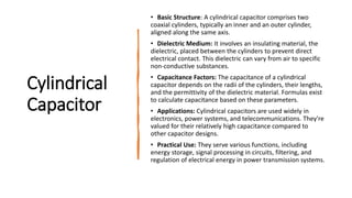
  • 1. Cylindrical Capacitor • Basic Structure: A cylindrical capacitor comprises two coaxial cylinders, typically an inner and an outer cylinder, aligned along the same axis. • Dielectric Medium: It involves an insulating material, the dielectric, placed between the cylinders to prevent direct electrical contact. This dielectric can vary from air to specific non-conductive substances. • Capacitance Factors: The capacitance of a cylindrical capacitor depends on the radii of the cylinders, their lengths, and the permittivity of the dielectric material. Formulas exist to calculate capacitance based on these parameters. • Applications: Cylindrical capacitors are used widely in electronics, power systems, and telecommunications. They're valued for their relatively high capacitance compared to other capacitor designs. • Practical Use: They serve various functions, including energy storage, signal processing in circuits, filtering, and regulation of electrical energy in power transmission systems.
  • 2. 1. A single-core cable or cylindrical capacitor consisting two co-axial cylinders of radii a and b metre. 2. Let the charge per metre length of the cable on the outer surface of the inner cylinder be + Q coulomb and on the inner surface of the outer cylinder be −Q coulomb. 3. Let εr be the relative permittivity of the medium between the two cylinders. The outer cylinder is earthed. 4. let us find the value of electric intensity at any point distant x metres from the axis of the inner cylinder. 5. Total flux coming out radially from the curved surface of this imaginary cylinder is Q coulomb. Area of the curved surface = 2 π x × 1 = 2 π x m2 .
  • 3.
  • 4.
  • 5. Potential Gradient in a Cylindrical Capacitor
  • 6.
  • 7.
  • 8.
  • 9. Capacitance Between Two Parallel Wires • This case is of practical importance in overhead transmission lines. The simplest system is 2-wire system (either d.c. or a.c.). In the case of a.c. system, if the transmission line is long and voltage high, the charging current drawn by the line due to the capacitance between conductors is appreciable and affects its performance considerably. • let d = distance between centres of the wires A and B • r = radius of each wire (≤d) • Q = charge in coulomb/metre of each wire • Now, let us consider electric intensity at any point P between conductors A and B. Electric intensity at P* due to charge + Q coulomb/metre on A is
  • 10.
  • 11.
  • 12. Capacitors in Series 1. C1 , C2 , C3 = Capacitances of three capacitors 2. V1 , V2 , V3 = p.ds. across three capacitors. 3. V = applied voltage across combination 4. C = combined or equivalent or joining capacitance. In series combination, charge on all capacitors is the same but p.d. across each is different.
  • 13. Capacitors in Parallel In this case, p.d. across each is the same but charge on each is different. ∴ Q = Q1 + Q2 + Q3 or CV = C1V + C2V + C3V or C = C1 + C2 + C3 For such a combination, dV/dt is the same for all capacitors.
  • 14. Cylindrical Capacitor with Compound Dielectric
  • 15.
  • 16.
  • 18. • Current Flow in Cable Capacitor: Current primarily flows along the axis of the core in a cable capacitor, serving its intended purpose. • Leakage of Current: However, some current inevitably leaks, and this leakage occurs radially, perpendicular to the intended current flow. • Insulation Resistance: The resistance presented to this radial leakage current is termed as the insulation resistance of the cable. • Relation to Cable Length: With longer cable lengths, there's an increase in leakage due to the radial current flow, resulting in reduced insulation resistance. In essence, as cable length grows, more current leaks, leading to a decrease in insulation resistance. • Inverse Proportionality: The relationship between insulation resistance and cable length is inversely proportional. Longer cables exhibit lower insulation resistance due to increased leakage. • Differentiation from Conductor Resistance: It's crucial not to confuse insulation resistance with conductor resistance. Insulation resistance pertains to the resistance against radial leakage and varies with cable length, whereas conductor resistance, related to the conductor material, is directly proportional to the cable length.
  • 19.
  • 20.
  • 21. Energy Stored in a Capacitor • Initial Energy Expenditure: Charging a capacitor requires energy from an external source. This energy is stored within the electrostatic field that forms in the dielectric medium. • Energy Storage and Discharge: The energy expended during charging gets stored in the electrostatic field. Upon discharge, this stored energy is released as the field collapses. • Work During Charging: Initially, when the capacitor is uncharged, minimal work is needed to transfer charge between the plates. However, as more charge is added, overcoming the repulsive force between the accumulated charges demands additional work. • Calculation of Energy Spent: The energy spent in charging a capacitor of capacitance C to a voltage V can be determined. At any point during charging, if the potential difference across the plates is v and the next charge increment transferred is 'dq', the work done is involved in moving 'dq' charge from one plate to the other.
  • 22.
  • 23.
  • 24. Force of Attraction Between Oppositely- charged Plates 1. Two parallel conducting plates A and B carrying constant charges of + Q and −Q coulombs respectively. Let the force of attraction between the two be F newtons. If one of the plates is pulled apart by distance dx, then work done is = F × dx joules ...(i) 2. Since the plate charges remain constant, no electrical energy comes into the arrangement during the movement dx. 3. ∴ Work done = change in stored energy
  • 25.
  • 26.
  • 29.
  • 30.
  • 32. Discharging of a Capacitor • when S is shifted to b, C is discharged through R. It will be seen that the discharging current flows in a direction opposite to that the charging current. • Hence, if the direction of the charging current is taken positive, then that of the discharging current will be taken as negative. To begin with, the discharge current is maximum but then decreases exponentially till it ceases when capacitor is fully discharged.
  • 33.
  • 34.
  • 35.
  • 36. Transient Relations During Capacitor Charging Cycle 1. Steady-State Transition: When a circuit moves from one stable state to another, it goes through a transient state. This transient state is brief compared to the overall duration. 2. Initial and Final Conditions: The initial state is the starting stable condition, and the final state is the target stable condition of the circuit. 3. Transient Phase: The transient state occurs between the initial and final conditions. It represents the period during which changes in current and voltage occur in the circuit. 4. Example with RC Circuit: Consider an RC circuit where initially, the switch isn't connected (at neither a nor b). This is the initial steady state with no current flow and consequently no voltage drops across components. 5. Switch Position Change: When the switch moves to position a, current flows through resistor R, initiating changes in voltage across R and the capacitor C. During this phase, transient voltages develop until they reach their stable, final values. 6. Duration of Transient Condition: The time frame in which current and voltage variations occur and stabilize is termed as the transient condition in the circuit. In essence, this process describes how a circuit, such as an RC circuit, undergoes changes in current and voltage as it transitions from an initial stable state to a final stable state, passing through a brief transient state in between.
  • 37.
  • 38. Transient Relations During Capacitor Discharging Cycle
  • 39. Charging and Discharging of a capacitor with Initial Charge • Initial Capacitor Potential: In this scenario, the capacitor starts with an initial potential (Vo) that is lower than the applied battery voltage (V). • Opposition to Applied Voltage: The initial potential (Vo) acts in opposition to the battery voltage (V) during the charging process. • Effect on Rate of Rise: illustrates that the initial rate of rise of the capacitor voltage (vc ) is somewhat slower when the capacitor begins with an initial potential (V) compared to when it starts uncharged. • Rise from V to Final V: The capacitor's voltage rises from the initial value (V0 ) to the final value (V) over one time constant. • Calculation of Initial Rate of Rise: The initial rate of rise of the capacitor voltage (vc ) from an initial value of V0 to the final value of V in one time constant can be determined based on the specific circuit characteristics and the relationship between the initial and final voltages.
  • 40.
  • 41.
  • 42.
  • 43.
  • 44.
  • 45.
  • 46.
  • 47.
  • 48. Thank You and Subscribe the channel & Like the video