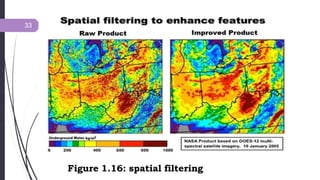
1
TITLE:
DIGITAL IMAGE PROCESSING
Introduction
2  Visual image interpretation techniques have certain disadvantages and may
require extensive training and are labor intensive.
In this technique, the spectral characteristics are not always fully evaluated
because of the limited ability of the eye to discern tonal value and analyze
the spectral changes.
If the data are in digital mode, the remote sensing data can be analyzed
using digital image processing techniques and such a data base can be used
in Raster GIS.
In applications where spectral patterns are more informative, it is
preferable to analyze digital data rather than pictorial data.
Definition
 Digital Image Processing is the manipulation of the digital data with
the help of the computer hardware and software to produce digital
maps in which specific information has been extracted and
highlighted.
3
4
The Origin of Digital image Processing
. The first application was in newspaper industry in 1920s
Different Stages in Digital Image Processing
 Satellite remote sensing data in general and digital data in particular have
been used as basic inputs for the inventory and mapping of natural
resources of the earth surface like forestry, soils, geology and agriculture.
Space borne remote sensing data suffer from a variety of radiometric,
atmospheric and geometric errors, earth‟s rotation and so on.
These distortions would diminish the accuracy of the information
extracted and reduce the utility of the data. So these errors required to
be corrected.
5
In order to update and compile maps with high accuracy, the satellite digital
data have to be manipulated using image process techniques.
Digital image data is fed into the computer, and the computer is
programmed to insert these data into an equation or a series of equation,
and then store the results of the competition of each and every pixel.
These results are called look–up–table (LTU) values for a new image that
may be manipulated further to extract information of user‟s interest.
Virtually, all the procedure may be grouped into one or more of the
following broad types of the operations, namely,
1. pre – processing, and
2. Image Processing.
Pre – processing
 Remotely sensed raw data generally contains flaws and deficiencies received
from imaging sensor mounted on the satellite. The correction of deficiencies
and removal of flaws present in the data through some methods are termed as
pre–processing methods this correction model involves to correct geometric
distortions, to calibrate the data radiometrically and to eliminate noise
present in the data. All the pre–processing methods are consider under three
heads, namely,
a) Radiometric correction method
b) Atmospheric correction method
c) Geometric correction methods
7
Radiometric correction method
 Radiometric errors are caused by detected imbalance and
atmospheric deficiencies. Radiometric corrections are
transformation on the data in order to remove error, which
are geometrically independent. Radiometric corrections are
also called as cosmetic corrections and are done to improve
the visual appearance of the image. Some of the radiometric
distortions are as follows:
1. Correction for missing lines
2. Correction for periodic line striping
3. Random noise correction
8
9
Correction for Missing Lines
10
Figure 1.3a: Random noise correction
11
Figure 1.3b: Random noise correction
12
Figure 1.4: Correction for periodic line striping
Atmospheric correction method
 The value recorded at any pixel location on the remotely sensed image
is not a record of the true ground – leaving radiant at that point, for the
signal is attenuated due to absorption and scattering.
The atmosphere has effect on the measured brightness value of a pixel.
Other difficulties are caused by the variation in the illumination
geometry.
Atmospheric path radiance introduces haze in the imagery where by
decreasing the contrast of the data.
13
14
Figure 1.5: Major Effects due to Atmosphere.
15
Figure 1.6: Atmospheric correction
Geometric correction methods
 Remotely sensed images are not maps. Frequently information extracted
from remotely sensed images is integrated with the map data in
Geographical Information System (GIS). The transformation of the
remotely sensed image into a map with the scale and projection properties is
called geometric corrections. Geometric corrections of remotely sensed
image is required when the image is to be used in one of the following
circumstances:
I. Totransform an image to match your map projection
II. Tolocate points of the interest on map and image.
III. To overlay temporal sequence of images of the same area, perhaps acquired
by different sensors.
IV. Tointegrate remotely sensed data with GIS.
16
17
What is Geometric correction?
18
Figure 1.7: Sample Geometric Distortions
19
Figure 1.8: Geometric correction
20
Figure 1.9: The flow of geometric
correction
Systematic Correction: when the geometric reference data or geometry
of sensor are given or measured, the geometric distortion can be
systematically avoided. Generally systematic correction is sufficient to
remove all errors.
Non-systematic Correction: polynomials to transform from a geographic
coordinate system, or vice versa, will be determined with the given
coordinates of the ground control points using the least square method.
The accuracy depends on the order of the polynomials and the number and
distribution of ground control points.
Combined method: Firstly systematic correction is applied, then the
residual errors are reduced using lower order polynomials. Usually the
goal of geometric correction is to obtain an error within plus or minus one
pixel of its true position.
21
must be
Internal errors are due to sensor effects, being systematic or stationary.
External errors are due to platform perturbations and scene characteristics
which are invariable in nature and can be determined from ground control
and tracing data.
In order to remove the haze component due to these disturbances to simple
techniques are applied:
I. Histogram Minimum Method, and
II. Regression Method.
To correct sensor data with GIS internal and external errors
22
determined and be either predictable or measureable.
23
Fig 1.10: It is an example of a contrast
stretch. Histogram A represents the pixel
values in image A. By stretching the values
(shown in histogram B) across the entire
range, you can alter and visually enhance
the appearance of the image (image B).
Image Processing:
 The second stage in Digital Image Processing entailsfive
different operations, namely,
A.Image Registration
B.Image Enhancement
C.Image Filtering
D.Image Transformation
E. Image Classification
All these are discussed in details below:
24
Image Registration
Image registration is the translation and alignment process by which two images/maps of
like geometrics and of the same set of objects are positioned co-incident with respect to
one another so that corresponding element of the same ground area appear in the same
place on the registered images.
This is often called image to image registration. One more important concept with respect
to geometry of satellite image is rectification. Rectification is the process by which the
geometry of an image area is made planimetric.
This process almost always involves relating Ground Control Point (GCP), pixel
coordinates with precise geometric correction since each pixel can be referenced not
only by the row or column in a digital image, but it is also rigorously referenced in
degree, feet or meters in a standard map projection whenever accurate data, direction and
distance measurements are acquired, geometric rectification is required.
This is often called as image to map rectification.
26
Figure 1.11: Image Registration
27
Figure 1.12: Image Registration
Image Enhancement
 Low sensitivity of the detector, weak signal of the objects present on the
earth surface, similar reflectance of different objects and environmental
conditions at the time of recording are the major causes of low contrast of
the image. Another problem that complicates photographic display of
digital image is that the human eye is poor at discriminating the slight
spectral or radiometric differences that may characterize the feature.
 Image enhancement techniques improve the quality of an image as
perceived by human eye. There exist a wide variety of techniques for
edge
used
improving image quality. contrast stretch, density slicing,
enhancement, and spatial filtering are the most commonly
techniques.
Image enhancement method are applied separately to each band of a
multispectral image.
28
29
Figure 1.13: Contrast Enhancement by Histogram Stretch
30
Figure 1.14: Density Slice for Surface Temperature
Visualization
31
Figure 1.15: Edge Enhancement
33
Figure 1.16: spatial filtering
Image Filtering

34
A characteristic of remotely sensed images is a parameter called spatial
frequency, defined as number of Changes in brighter value per unit distance for
any particular part of an image. Few brighter changes in an image considered as
low frequency, conversely, the brighter value changes dramatically over short
distance, this is an area of high frequency.
 Spatial filtering is the process of dividing the image into its constituent spatial
frequency and selectively altering certain spatial features. This technique
increases the analyst‟s ability to discriminate details. The three types of spatial
filters used in remote sensor data processing are:
1. Low Pass Filters,
2. Band Pass Filters, and
3. High Pass Filters.
35
Contrast-stretched
Image
Low Pass
Filter Image
36
High Pass Filter Image
Original Image
37
Figure 1.17: In the example, we add some sinusoidal noise to an
image and filter it with Band Pass Filter
Image Transformation
 All the transformations in an image based on arithmetic
operations. The resulting images may will have properties
that make them more suited for a particular purpose than the
original.
The transformation which is commonly used as follows:
Principal Component Analysis (PCA)
38
Principal Component Analysis (PCA)
 The application of Principal Component Analysis (PCA) on raw remotely
sensed data producing a new image which is more interpretable than the
original data. The main advantage of PCA is that it may be used to compress
the information content of a number of bands into just two or three
transformed principal component images.
42
43
Figure 1.20: The application of Principal
Component Analysis (PCA) on raw remotely
sensed data of UrbanArea by Unsupervised
Classification.
Image Classification
44
Image Classification is a procedure to automatically categorise all pixel in an
image of a terrain into land use and land cover classes. This concept is dealt
under broad subject, namely, “pattern recognition”. Spectral pattern recognition
refers to the family of classification procedures that utilises this pixel-by-pixel
spectral information as the basis for automated land cover classification. Spatial
pattern recognition of image on the basis of the spatial relationship with pixel
surrounding.
Image classification technique are grouped into two types, namely,
1. Supervised Classification , and
2. Unsupervised Classification.
Supervised Classification
 Different phases in supervised Classification technique are as
follows:
(i) Appropriate classification scheme for analysis is adopted.
(ii)Selection of representative training sites and collection of
spectral signatures.
(iii)Evaluation of statics for the training site spectral data.
(iv)The statics are analyzed to select the appropriate features to
be used in classification process.
(v)Appropriate classification algorithm is selected.
(vi)Then classify the image into „n‟number ofclasses.
45
46
Figure 1.21: Supervised Classification
Unsupervised Classification
47
The Unsupervised Classifiers do not utilize training data as basis for classification. These classifiers examine the
unknown pixel and aggregate them into a number of class based on natural grouping or clusters present in the image
values. The classes that result from unsupervised classification are spectral classes.
The analyst must compare the classified data into some form of reference data to identify the informational value of the
spectral classes.
 It has been found that in areas of complex terrain, the unsupervised approach is preferable. In such conditions, if the
supervised approach is used, the user will have difficulty in selecting training sites because of variability of spectral
response within them each class.
Consequently, group data collected but it is very time consuming. Also, the supervised approach is subjective in the sense
that the analyst tries to classify information categories, which are often composed of several spectral classes, whereas
spectrally distinguishable classes will be revealed by the unsupervised approach.
Additionally, the unsupervised approach has potential advantage of revealing discrimination classes unknown from the
previous supervised classification.
48
Figure 1.22: In an unsupervised classification, a thematic map of the input image is created
automatically in ENVI without requiring any pre-existing knowledge of the input image. The
unsupervised classification method performs an automatic grouping; the next step in this
workflow is for the user to assign names to each of the automatically generated regions (for
References
Campbell, J.B. and Wynne, R. H. (2010). Introduction to
Remote Sensing, The Guilford Press, New York.pp.
 Jayaraman, S., Esakkirajan, S. and Veerakumar, T.(2016).
Digital Image Processing, McGraw Hill Education (India)
pvt. Ltd., New Delhi. pp. 243-297
Bhatta, B.(2015). Remote Sensing and GIS, Oxford
university press, New Delhi. pp. 196–223
49

3.1 Digital Image Proccessing.pptx

  • 1.
  • 2.
    Introduction 2  Visualimage interpretation techniques have certain disadvantages and may require extensive training and are labor intensive. In this technique, the spectral characteristics are not always fully evaluated because of the limited ability of the eye to discern tonal value and analyze the spectral changes. If the data are in digital mode, the remote sensing data can be analyzed using digital image processing techniques and such a data base can be used in Raster GIS. In applications where spectral patterns are more informative, it is preferable to analyze digital data rather than pictorial data.
  • 3.
    Definition  Digital ImageProcessing is the manipulation of the digital data with the help of the computer hardware and software to produce digital maps in which specific information has been extracted and highlighted. 3
  • 4.
    4 The Origin ofDigital image Processing . The first application was in newspaper industry in 1920s
  • 5.
    Different Stages inDigital Image Processing  Satellite remote sensing data in general and digital data in particular have been used as basic inputs for the inventory and mapping of natural resources of the earth surface like forestry, soils, geology and agriculture. Space borne remote sensing data suffer from a variety of radiometric, atmospheric and geometric errors, earth‟s rotation and so on. These distortions would diminish the accuracy of the information extracted and reduce the utility of the data. So these errors required to be corrected. 5
  • 6.
    In order toupdate and compile maps with high accuracy, the satellite digital data have to be manipulated using image process techniques. Digital image data is fed into the computer, and the computer is programmed to insert these data into an equation or a series of equation, and then store the results of the competition of each and every pixel. These results are called look–up–table (LTU) values for a new image that may be manipulated further to extract information of user‟s interest. Virtually, all the procedure may be grouped into one or more of the following broad types of the operations, namely, 1. pre – processing, and 2. Image Processing.
  • 7.
    Pre – processing Remotely sensed raw data generally contains flaws and deficiencies received from imaging sensor mounted on the satellite. The correction of deficiencies and removal of flaws present in the data through some methods are termed as pre–processing methods this correction model involves to correct geometric distortions, to calibrate the data radiometrically and to eliminate noise present in the data. All the pre–processing methods are consider under three heads, namely, a) Radiometric correction method b) Atmospheric correction method c) Geometric correction methods 7
  • 8.
    Radiometric correction method Radiometric errors are caused by detected imbalance and atmospheric deficiencies. Radiometric corrections are transformation on the data in order to remove error, which are geometrically independent. Radiometric corrections are also called as cosmetic corrections and are done to improve the visual appearance of the image. Some of the radiometric distortions are as follows: 1. Correction for missing lines 2. Correction for periodic line striping 3. Random noise correction 8
  • 9.
  • 10.
    10 Figure 1.3a: Randomnoise correction
  • 11.
    11 Figure 1.3b: Randomnoise correction
  • 12.
    12 Figure 1.4: Correctionfor periodic line striping
  • 13.
    Atmospheric correction method The value recorded at any pixel location on the remotely sensed image is not a record of the true ground – leaving radiant at that point, for the signal is attenuated due to absorption and scattering. The atmosphere has effect on the measured brightness value of a pixel. Other difficulties are caused by the variation in the illumination geometry. Atmospheric path radiance introduces haze in the imagery where by decreasing the contrast of the data. 13
  • 14.
    14 Figure 1.5: MajorEffects due to Atmosphere.
  • 15.
  • 16.
    Geometric correction methods Remotely sensed images are not maps. Frequently information extracted from remotely sensed images is integrated with the map data in Geographical Information System (GIS). The transformation of the remotely sensed image into a map with the scale and projection properties is called geometric corrections. Geometric corrections of remotely sensed image is required when the image is to be used in one of the following circumstances: I. Totransform an image to match your map projection II. Tolocate points of the interest on map and image. III. To overlay temporal sequence of images of the same area, perhaps acquired by different sensors. IV. Tointegrate remotely sensed data with GIS. 16
  • 17.
  • 18.
    18 Figure 1.7: SampleGeometric Distortions
  • 19.
  • 20.
    20 Figure 1.9: Theflow of geometric correction
  • 21.
    Systematic Correction: whenthe geometric reference data or geometry of sensor are given or measured, the geometric distortion can be systematically avoided. Generally systematic correction is sufficient to remove all errors. Non-systematic Correction: polynomials to transform from a geographic coordinate system, or vice versa, will be determined with the given coordinates of the ground control points using the least square method. The accuracy depends on the order of the polynomials and the number and distribution of ground control points. Combined method: Firstly systematic correction is applied, then the residual errors are reduced using lower order polynomials. Usually the goal of geometric correction is to obtain an error within plus or minus one pixel of its true position. 21
  • 22.
    must be Internal errorsare due to sensor effects, being systematic or stationary. External errors are due to platform perturbations and scene characteristics which are invariable in nature and can be determined from ground control and tracing data. In order to remove the haze component due to these disturbances to simple techniques are applied: I. Histogram Minimum Method, and II. Regression Method. To correct sensor data with GIS internal and external errors 22 determined and be either predictable or measureable.
  • 23.
    23 Fig 1.10: Itis an example of a contrast stretch. Histogram A represents the pixel values in image A. By stretching the values (shown in histogram B) across the entire range, you can alter and visually enhance the appearance of the image (image B).
  • 24.
    Image Processing:  Thesecond stage in Digital Image Processing entailsfive different operations, namely, A.Image Registration B.Image Enhancement C.Image Filtering D.Image Transformation E. Image Classification All these are discussed in details below: 24
  • 25.
    Image Registration Image registrationis the translation and alignment process by which two images/maps of like geometrics and of the same set of objects are positioned co-incident with respect to one another so that corresponding element of the same ground area appear in the same place on the registered images. This is often called image to image registration. One more important concept with respect to geometry of satellite image is rectification. Rectification is the process by which the geometry of an image area is made planimetric. This process almost always involves relating Ground Control Point (GCP), pixel coordinates with precise geometric correction since each pixel can be referenced not only by the row or column in a digital image, but it is also rigorously referenced in degree, feet or meters in a standard map projection whenever accurate data, direction and distance measurements are acquired, geometric rectification is required. This is often called as image to map rectification.
  • 26.
  • 27.
  • 28.
    Image Enhancement  Lowsensitivity of the detector, weak signal of the objects present on the earth surface, similar reflectance of different objects and environmental conditions at the time of recording are the major causes of low contrast of the image. Another problem that complicates photographic display of digital image is that the human eye is poor at discriminating the slight spectral or radiometric differences that may characterize the feature.  Image enhancement techniques improve the quality of an image as perceived by human eye. There exist a wide variety of techniques for edge used improving image quality. contrast stretch, density slicing, enhancement, and spatial filtering are the most commonly techniques. Image enhancement method are applied separately to each band of a multispectral image. 28
  • 29.
    29 Figure 1.13: ContrastEnhancement by Histogram Stretch
  • 30.
    30 Figure 1.14: DensitySlice for Surface Temperature Visualization
  • 31.
  • 32.
  • 33.
    Image Filtering  34 A characteristicof remotely sensed images is a parameter called spatial frequency, defined as number of Changes in brighter value per unit distance for any particular part of an image. Few brighter changes in an image considered as low frequency, conversely, the brighter value changes dramatically over short distance, this is an area of high frequency.  Spatial filtering is the process of dividing the image into its constituent spatial frequency and selectively altering certain spatial features. This technique increases the analyst‟s ability to discriminate details. The three types of spatial filters used in remote sensor data processing are: 1. Low Pass Filters, 2. Band Pass Filters, and 3. High Pass Filters.
  • 34.
  • 35.
    36 High Pass FilterImage Original Image
  • 36.
    37 Figure 1.17: Inthe example, we add some sinusoidal noise to an image and filter it with Band Pass Filter
  • 37.
    Image Transformation  Allthe transformations in an image based on arithmetic operations. The resulting images may will have properties that make them more suited for a particular purpose than the original. The transformation which is commonly used as follows: Principal Component Analysis (PCA) 38
  • 38.
    Principal Component Analysis(PCA)  The application of Principal Component Analysis (PCA) on raw remotely sensed data producing a new image which is more interpretable than the original data. The main advantage of PCA is that it may be used to compress the information content of a number of bands into just two or three transformed principal component images. 42
  • 39.
    43 Figure 1.20: Theapplication of Principal Component Analysis (PCA) on raw remotely sensed data of UrbanArea by Unsupervised Classification.
  • 40.
    Image Classification 44 Image Classificationis a procedure to automatically categorise all pixel in an image of a terrain into land use and land cover classes. This concept is dealt under broad subject, namely, “pattern recognition”. Spectral pattern recognition refers to the family of classification procedures that utilises this pixel-by-pixel spectral information as the basis for automated land cover classification. Spatial pattern recognition of image on the basis of the spatial relationship with pixel surrounding. Image classification technique are grouped into two types, namely, 1. Supervised Classification , and 2. Unsupervised Classification.
  • 41.
    Supervised Classification  Differentphases in supervised Classification technique are as follows: (i) Appropriate classification scheme for analysis is adopted. (ii)Selection of representative training sites and collection of spectral signatures. (iii)Evaluation of statics for the training site spectral data. (iv)The statics are analyzed to select the appropriate features to be used in classification process. (v)Appropriate classification algorithm is selected. (vi)Then classify the image into „n‟number ofclasses. 45
  • 42.
  • 43.
    Unsupervised Classification 47 The UnsupervisedClassifiers do not utilize training data as basis for classification. These classifiers examine the unknown pixel and aggregate them into a number of class based on natural grouping or clusters present in the image values. The classes that result from unsupervised classification are spectral classes. The analyst must compare the classified data into some form of reference data to identify the informational value of the spectral classes.  It has been found that in areas of complex terrain, the unsupervised approach is preferable. In such conditions, if the supervised approach is used, the user will have difficulty in selecting training sites because of variability of spectral response within them each class. Consequently, group data collected but it is very time consuming. Also, the supervised approach is subjective in the sense that the analyst tries to classify information categories, which are often composed of several spectral classes, whereas spectrally distinguishable classes will be revealed by the unsupervised approach. Additionally, the unsupervised approach has potential advantage of revealing discrimination classes unknown from the previous supervised classification.
  • 44.
    48 Figure 1.22: Inan unsupervised classification, a thematic map of the input image is created automatically in ENVI without requiring any pre-existing knowledge of the input image. The unsupervised classification method performs an automatic grouping; the next step in this workflow is for the user to assign names to each of the automatically generated regions (for
  • 45.
    References Campbell, J.B. andWynne, R. H. (2010). Introduction to Remote Sensing, The Guilford Press, New York.pp.  Jayaraman, S., Esakkirajan, S. and Veerakumar, T.(2016). Digital Image Processing, McGraw Hill Education (India) pvt. Ltd., New Delhi. pp. 243-297 Bhatta, B.(2015). Remote Sensing and GIS, Oxford university press, New Delhi. pp. 196–223 49