Downloaded 38 times


![13
Power Plant Operation Modes
Normal Mode
• This is also known as the turbine-leading-boiler mode or (Boiler-lagging). As its name implies, it is
normally the preferred mode of operation, as it is designed to serve the needs of the power grid.
• If this mode is selected, the unit’s operator specifies generator electrical output as the set-point:
the operator sets the target electric power output [say, in MW, or in % of Full Power (FP)], and
the target rate of change of power [e.g., in % FP/s].
• The control program (running in the station computer) is called the Unit Power Regulator (UPR).
• The UPR continuously compares the actual generator power to the setpoint.
Alternate Mode
• This is also known as the boiler-leading-turbine mode (or turbine-lagging). This is not normally
the preferred mode of operation, but is used under certain circumstances, especially if the
reactor power has to be strictly controlled.
• If this mode is selected, the unit’s operator specifies reactor power as the setpoint: the operator
sets the target reactor power output [say, in % of reactor Full Power (FP)], and the target rate of
change of reactor power [e.g., in % FP/s].
• The RRS continuously compares the actual reactor power to the setpoint.
• If there is a difference, there is a “reactor-power error”.
Invensys proprietary](https://image.slidesharecdn.com/schneiderprocessautomationpowerindustrysolutionsli-170128073504/85/Schneider-process-automation-power-industry-solutions-13-320.jpg)
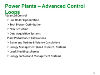
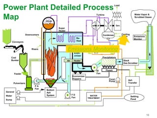
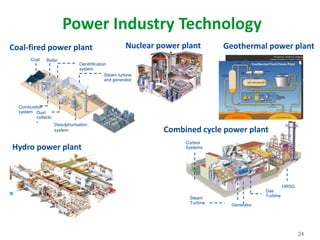
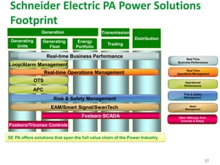

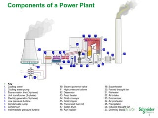
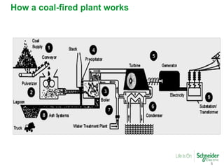
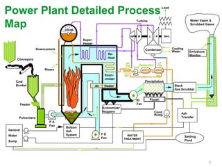
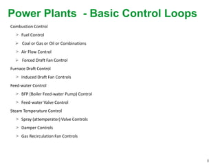
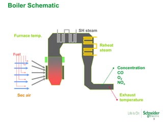
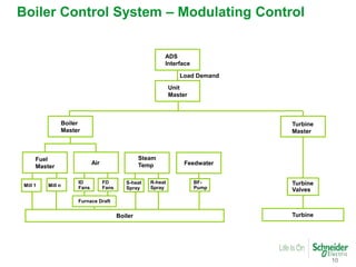
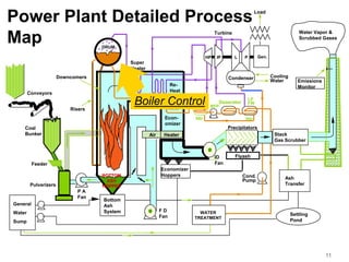
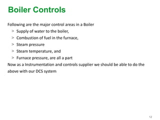
This document provides an overview of components and processes in a coal-fired power plant. It describes the key components including the boiler, turbine, generator, cooling systems and emissions controls. It explains the basic process of how coal is combusted to produce steam to drive the turbine and generate electricity. It also discusses boiler and plant control systems, operating modes, and advanced process control solutions for optimization.


