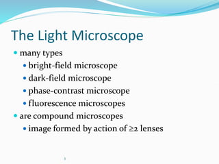
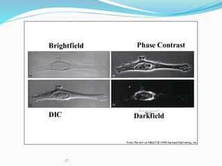
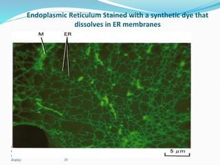
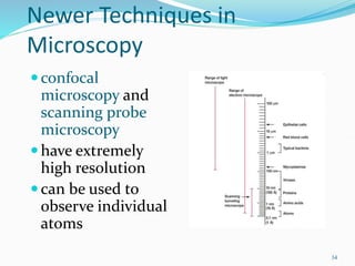
 History
 Parts
 Care
 Types
Lecture 2: Dr. Prince Amoah Barnie
2
3
The Light Microscope
 many types
 bright-field microscope
 dark-field microscope
 phase-contrast microscope
 fluorescence microscopes
 are compound microscopes
 image formed by action of 2 lenses
4
The light microscope
 has several objective lenses
 parfocal microscopes remain in focus when
objectives are changed
 total magnification
 product of the magnifications of the ocular
lens and the objective lens
. 5
The Bright-Field Microscope
produces a dark image against a brighter
background
uses a prism to send the light to both eyes
light passing through specimen is diffracted
and absorbed to make image
Staining is often necessary because very low
contrast
. 6
Microscope Resolution
 ability of a lens to separate or distinguish small
objects that are close together
 wavelength of light used is major factor in
resolution
shorter wavelength  greater resolution
7
•working distance
— distance between the front surface of lens and surface of cover
glass or specimen
8
9
The Dark-Field Microscope
produces a bright image of the object
against a dark background
used to observe living, unstained
preparations
10
The Phase-Contrast Microscope
A phase ring in condenser allows a cylinder
of light through in phase.
Light that is unaltered hits the phase ring in
the lens and is excluded.
Light that is slightly altered by passing
through different refractive index is allowed
through.
11
The Phase-Contrast
Microscope
 Light passing through cellular structures
such as chromosomes or mitochondria is
retarded because they have a higher
refractive index than the surrounding
medium.
 Elements of lower refractive index advance
the wave. Much of the background light is
removed and light that constructively or
destructively interfered is let through with
enhanced contrast
12
The Phase-Contrast
Microscope
Visualizes differences in refractive index
of different parts of a specimen relative
to the unaltered light
enhances the contrast between
intracellular structures having slight
differences in refractive index
excellent way to observe living cells
13
The Differential Interference
Contrast Microscope or Nomarski
creates image by detecting differences in
refractive indices and thickness of
different parts of specimen
excellent way to observe living cells
. 14
The Differential Interference
Contrast Microscope or Nomarski
creates image by detecting differences in
refractive indices and thickness of
different parts of specimen.
excellent way to observe living cells.
a prism is used to split light into two
slightly diverging beams that then pass
through the specimen.
15
The Differential Interference
Contrast Microscope or Nomarski
On recombining the two beams, if they
pass through difference in refractive
index then one retarded or advanced
relative to the other and so they can
interfere.
By changing the prism you can change
the beam separation which can alter the
contrast.
16
The Differential Interference
Contrast Microscope or Nomarski
Also measures refractive index changes,
but for narrowly separated regions of
light paths-ie it measures the gradient
across the specimen
Gives a shadowed 3D effect
Optically sections through a specimen
17
Brightfield Phase Contrast
DIC Darkfield
18
The Fluorescence Microscope
exposes specimen to ultraviolet, violet, or
blue light
specimens usually stained with
fluorochromes
shows a bright image of the object
resulting from the fluorescent light
emitted by the specimen
19
The Fluorescence Microscope
Fluorescent dye- a molecule that absorbs
light of one wavelength and then re-emits it
at a longer wavelength
Can be used alone or in combination with
another molecule to gain specificity
(antibodies)
Copyright © The McGraw-Hill
Companies, Inc. Permission
required for reproduction or
display. 20
Endoplasmic Reticulum Stained with a synthetic dye that
dissolves in ER membranes
21
Preparation and Staining of
Specimens
increases visibility of specimen
accentuates specific morphological
features
preserves specimens
22
Fixation
process by which internal and external
structures are preserved and fixed in
position
process by which organism is killed and
firmly attached to microscope slide
 heat fixing
 preserves overall morphology but not internal
structures
 chemical fixing
 protects fine cellular substructure and
morphology of larger, more delicate organisms
23
Dyes and Simple Staining
 dyes
 make internal and external structures of cell
more visible by increasing contrast with
background
 have two common features
 chromophore groups
 chemical groups with conjugated double
bonds
 give dye its color
 ability to bind cells
. 24
Dyes and Simple Staining
simple staining
a single staining agent is used
basic dyes are frequently used
 dyes with positive charges
 e.g., crystal violet
. 25
Differential Staining
 divides microorganisms into groups based on
their staining properties
 e.g., Gram stain
 e.g., acid-fast stain
26
Gram staining
most widely used differential staining
procedure
divides Bacteria into two groups based on
differences in cell wall structure
27
Escherichia coli – a gram-negative rod
28
Acid-fast staining
 particularly useful for staining members of the genus
Mycobacterium
e.g., Mycobacterium tuberculosis – causes
tuberculosis
e.g., Mycobacterium leprae – causes leprosy
 high lipid content in cell walls is responsible for their
staining characteristics
29
Staining Specific Structures
Negative staining
often used to visualize capsules
surrounding bacteria
capsules are colorless against a stained
background
30
Staining Specific Structures
 Spore staining
 double staining technique
 bacterial endospore is one color and
vegetative cell is a different color
 Flagella staining
 mordant applied to increase thickness of
flagella
31
Electron Microscopy
beams of electrons
are used to
produce images
wavelength of
electron beam is
much shorter than
light, resulting in
much higher
resolution
Figure 2.20
32
The Transmission Electron
Microscope
electrons scatter when they pass through
thin sections of a specimen
transmitted electrons (those that do not
scatter) are used to produce image
denser regions in specimen, scatter more
electrons and appear darker
33
The Scanning Electron Microscope
uses electrons reflected from the surface
of a specimen to create image
produces a 3-dimensional image of
specimen’s surface features
34
Newer Techniques in
Microscopy
confocal
microscopy and
scanning probe
microscopy
have extremely
high resolution
can be used to
observe individual
atoms
35
Confocal Microscopy
confocal scanning laser microscope
laser beam used to illuminate spots on
specimen
computer compiles images created from
each point to generate a 3-dimensional
image
36
Confocal Microscopy
 Fluorescence microscope
 Uses “confocality” (a pinhole) to eliminate
fluorescence from out of focus planes
 Minimum Z resolution=0.3µm
 Because you can optically section through a
specimen, you can determine the localization of
probes in the Z dimension
 You can also build 3D (4D) models of structures
and cells from the data
37
Confocal Microscopy
Uses a laser to get a high energy point
source of light
The beam is scanned across the specimen
point by point and the fluorescence
measured at each point
The result is displayed on a computer
screen (quantitative data)
38
Confocal Microscopy
Spinning disk confocal microscope
Illuminates the whole field “simultaneously
with a field of points
Captures images of the whole field at once
with a camera
Much faster than CSLM
Can be viewed through eyepieces
. 39
Confocal Microscopy
Two photon confocal microscope
 A fluor like fluorescein normally absorbs a photon of about 480nm
and emits one at about 530nm
 If fluorescein absorbs two photons of 960nm near enough to each
other in time so that the first does not decay before the second is
absorbed, it will fluoresce- 2 photon fluorescence
 Confocal microscope with a laser that emits picosecond pulses of
light instead of a continuous beam is used
 Advantage
 960nm light penetrates farther into biological specimens
 The density of light is very high at focal point, but low
elsewhere, so damage to cell is less
 You don’t need a second pinhole because excitation only
happens at the focal point
40
Scanning Probe Microscopy
 scanning tunneling microscope
 steady current (tunneling current)
maintained between microscope probe and
specimen
 up and down movement of probe as it
maintains current is detected and used to
create image of surface of specimen
41
Scanning Probe Microscopy
atomic force microscope
sharp probe moves over surface of
specimen at constant distance
up and down movement of probe as it
maintains constant distance is
detected and used to create image

2.0 - Types of Light Microscope.ppt microscope

  • 1.
     History  Parts Care  Types Lecture 2: Dr. Prince Amoah Barnie
  • 2.
  • 3.
    3 The Light Microscope many types  bright-field microscope  dark-field microscope  phase-contrast microscope  fluorescence microscopes  are compound microscopes  image formed by action of 2 lenses
  • 4.
    4 The light microscope has several objective lenses  parfocal microscopes remain in focus when objectives are changed  total magnification  product of the magnifications of the ocular lens and the objective lens
  • 5.
    . 5 The Bright-FieldMicroscope produces a dark image against a brighter background uses a prism to send the light to both eyes light passing through specimen is diffracted and absorbed to make image Staining is often necessary because very low contrast
  • 6.
    . 6 Microscope Resolution ability of a lens to separate or distinguish small objects that are close together  wavelength of light used is major factor in resolution shorter wavelength  greater resolution
  • 7.
    7 •working distance — distancebetween the front surface of lens and surface of cover glass or specimen
  • 8.
  • 9.
    9 The Dark-Field Microscope producesa bright image of the object against a dark background used to observe living, unstained preparations
  • 10.
    10 The Phase-Contrast Microscope Aphase ring in condenser allows a cylinder of light through in phase. Light that is unaltered hits the phase ring in the lens and is excluded. Light that is slightly altered by passing through different refractive index is allowed through.
  • 11.
    11 The Phase-Contrast Microscope  Lightpassing through cellular structures such as chromosomes or mitochondria is retarded because they have a higher refractive index than the surrounding medium.  Elements of lower refractive index advance the wave. Much of the background light is removed and light that constructively or destructively interfered is let through with enhanced contrast
  • 12.
    12 The Phase-Contrast Microscope Visualizes differencesin refractive index of different parts of a specimen relative to the unaltered light enhances the contrast between intracellular structures having slight differences in refractive index excellent way to observe living cells
  • 13.
    13 The Differential Interference ContrastMicroscope or Nomarski creates image by detecting differences in refractive indices and thickness of different parts of specimen excellent way to observe living cells
  • 14.
    . 14 The DifferentialInterference Contrast Microscope or Nomarski creates image by detecting differences in refractive indices and thickness of different parts of specimen. excellent way to observe living cells. a prism is used to split light into two slightly diverging beams that then pass through the specimen.
  • 15.
    15 The Differential Interference ContrastMicroscope or Nomarski On recombining the two beams, if they pass through difference in refractive index then one retarded or advanced relative to the other and so they can interfere. By changing the prism you can change the beam separation which can alter the contrast.
  • 16.
    16 The Differential Interference ContrastMicroscope or Nomarski Also measures refractive index changes, but for narrowly separated regions of light paths-ie it measures the gradient across the specimen Gives a shadowed 3D effect Optically sections through a specimen
  • 17.
  • 18.
    18 The Fluorescence Microscope exposesspecimen to ultraviolet, violet, or blue light specimens usually stained with fluorochromes shows a bright image of the object resulting from the fluorescent light emitted by the specimen
  • 19.
    19 The Fluorescence Microscope Fluorescentdye- a molecule that absorbs light of one wavelength and then re-emits it at a longer wavelength Can be used alone or in combination with another molecule to gain specificity (antibodies)
  • 20.
    Copyright © TheMcGraw-Hill Companies, Inc. Permission required for reproduction or display. 20 Endoplasmic Reticulum Stained with a synthetic dye that dissolves in ER membranes
  • 21.
    21 Preparation and Stainingof Specimens increases visibility of specimen accentuates specific morphological features preserves specimens
  • 22.
    22 Fixation process by whichinternal and external structures are preserved and fixed in position process by which organism is killed and firmly attached to microscope slide  heat fixing  preserves overall morphology but not internal structures  chemical fixing  protects fine cellular substructure and morphology of larger, more delicate organisms
  • 23.
    23 Dyes and SimpleStaining  dyes  make internal and external structures of cell more visible by increasing contrast with background  have two common features  chromophore groups  chemical groups with conjugated double bonds  give dye its color  ability to bind cells
  • 24.
    . 24 Dyes andSimple Staining simple staining a single staining agent is used basic dyes are frequently used  dyes with positive charges  e.g., crystal violet
  • 25.
    . 25 Differential Staining divides microorganisms into groups based on their staining properties  e.g., Gram stain  e.g., acid-fast stain
  • 26.
    26 Gram staining most widelyused differential staining procedure divides Bacteria into two groups based on differences in cell wall structure
  • 27.
    27 Escherichia coli –a gram-negative rod
  • 28.
    28 Acid-fast staining  particularlyuseful for staining members of the genus Mycobacterium e.g., Mycobacterium tuberculosis – causes tuberculosis e.g., Mycobacterium leprae – causes leprosy  high lipid content in cell walls is responsible for their staining characteristics
  • 29.
    29 Staining Specific Structures Negativestaining often used to visualize capsules surrounding bacteria capsules are colorless against a stained background
  • 30.
    30 Staining Specific Structures Spore staining  double staining technique  bacterial endospore is one color and vegetative cell is a different color  Flagella staining  mordant applied to increase thickness of flagella
  • 31.
    31 Electron Microscopy beams ofelectrons are used to produce images wavelength of electron beam is much shorter than light, resulting in much higher resolution Figure 2.20
  • 32.
    32 The Transmission Electron Microscope electronsscatter when they pass through thin sections of a specimen transmitted electrons (those that do not scatter) are used to produce image denser regions in specimen, scatter more electrons and appear darker
  • 33.
    33 The Scanning ElectronMicroscope uses electrons reflected from the surface of a specimen to create image produces a 3-dimensional image of specimen’s surface features
  • 34.
    34 Newer Techniques in Microscopy confocal microscopyand scanning probe microscopy have extremely high resolution can be used to observe individual atoms
  • 35.
    35 Confocal Microscopy confocal scanninglaser microscope laser beam used to illuminate spots on specimen computer compiles images created from each point to generate a 3-dimensional image
  • 36.
    36 Confocal Microscopy  Fluorescencemicroscope  Uses “confocality” (a pinhole) to eliminate fluorescence from out of focus planes  Minimum Z resolution=0.3µm  Because you can optically section through a specimen, you can determine the localization of probes in the Z dimension  You can also build 3D (4D) models of structures and cells from the data
  • 37.
    37 Confocal Microscopy Uses alaser to get a high energy point source of light The beam is scanned across the specimen point by point and the fluorescence measured at each point The result is displayed on a computer screen (quantitative data)
  • 38.
    38 Confocal Microscopy Spinning diskconfocal microscope Illuminates the whole field “simultaneously with a field of points Captures images of the whole field at once with a camera Much faster than CSLM Can be viewed through eyepieces
  • 39.
    . 39 Confocal Microscopy Twophoton confocal microscope  A fluor like fluorescein normally absorbs a photon of about 480nm and emits one at about 530nm  If fluorescein absorbs two photons of 960nm near enough to each other in time so that the first does not decay before the second is absorbed, it will fluoresce- 2 photon fluorescence  Confocal microscope with a laser that emits picosecond pulses of light instead of a continuous beam is used  Advantage  960nm light penetrates farther into biological specimens  The density of light is very high at focal point, but low elsewhere, so damage to cell is less  You don’t need a second pinhole because excitation only happens at the focal point
  • 40.
    40 Scanning Probe Microscopy scanning tunneling microscope  steady current (tunneling current) maintained between microscope probe and specimen  up and down movement of probe as it maintains current is detected and used to create image of surface of specimen
  • 41.
    41 Scanning Probe Microscopy atomicforce microscope sharp probe moves over surface of specimen at constant distance up and down movement of probe as it maintains constant distance is detected and used to create image