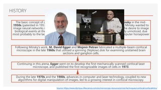
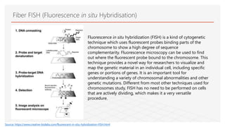
CONFOCAL MICROSCOPY
1. History – Vikram Aditya (17/06014)
2. Introduction – Vikram Aditya (17/06014)
3. Instrumentation – Vikram Aditya (17/06014)
4. Principle – Damini Pandita (17/06022)
5. Sample preparation – Deepanshu(17/06020)
6. Advantages and applications – Mansi (17/06016), Ujjwal (17/06018)
7. Limitations and Disadvantages – Shruti Khandelwal (17/06019)
8. Developments & variants – Damini (17/06022), Deepanshu(17/06020)
Guided by
Dr. Sunita Singh
Shivaji College, DU
HISTORY
The basic concept of confocal microscopy was originally developed by Marvin Minsky in the mid-
1950s (patented in 1957) when he was a postdoctoral student at Harvard University. Minsky wanted to
image neural networks in unstained preparations of brain tissue and was driven by the desire to image
biological events at they occur in living systems. Minsky's invention remained largely unnoticed, due
most probably to the lack of intense light sources necessary for imaging and the computer horsepower
required to handle large amounts of data.
Following Minsky's work, M. David Egger and Mojmir Petran fabricated a multiple-beam confocal
microscope in the late 1960s that utilized a spinning (Nipkow) disk for examining unstained brain
sections and ganglion cells.
Continuing in this arena, Egger went on to develop the first mechanically scanned confocal laser
microscope, and published the first recognizable images of cells in 1973.
During the late 1970s and the 1980s, advances in computer and laser technology, coupled to new
algorithms for digital manipulation of images, led to a growing interest in confocal microscopy.
Source: https://www.olympus-lifescience.com/en/microscope-resource/primer/techniques/confocal/confocalintro/
INTRODUCTION
Confocal microscopy offers several advantages over conventional widefield optical
microscopy, including the ability to control depth of field, elimination or
reduction of background information away from the focal plane (that leads to
image degradation), and the capability to collect serial optical
sections from thick specimens. The basic key to the confocal approach is the use of
spatial filtering techniques to eliminate out-of-focus light or glare in specimens whose
thickness exceeds the immediate plane of focus.
Source: https://www.olympus-lifescience.com/en/microscope-resource/primer/techniques/confocal/confocalintro/
INSTRUMENTATION
INSTRUMENTATION
Fig. Ray diagram of a confocal microscope
Source: https://www.olympus-lifescience.com/en/microscope-resource/primer/techniques/confocal/confocalintro/
INSTRUMENTATION
Fig. Image of a confocal microscope
Source: https://www.olympus-lifescience.com/en/microscope-resource/primer/techniques/confocal/confocalintro/
INSTRUMENTATION
Source: https://www.olympus-lifescience.com/en/microscope-resource/primer/techniques/confocal/confocalintro/
INSTRUMENTATION
Source: https://www.olympus-lifescience.com/en/microscope-resource/primer/techniques/confocal/confocalintro/
The confocal microscope uses fluorescence optics. Instead of
illuminating the whole sample at once, laser light is focused onto a
defined spot at a specific depth within the sample. This leads to the
emission of fluorescent light at exactly this point. A pinhole inside
the optical pathway cuts off signals that are out of focus, thus
allowing only the fluorescence signals from the illuminated spot to
enter the light detector.
By scanning the specimen in a raster pattern, images of one single
optical plane are created. 3D objects can be visualized by scanning
several optical planes and stacking them using a suitable microscopy
deconvolution software (z-stack). It is also possible to analyze
multicolor immunofluorescence stainings using state-of-the-art
confocal microscopes that include several lasers and
emission/excitation filters.
Source: https://ibidi.com/content/216-confocal-microscopy
PRINCIPLE
Excitation and emission light
pathways in a basic confocal
microscope configuration.
SAMPLE PREPARATION
Specimens that have three-
dimensional structure that is
to be studied with the confocal
microscope, have to be
mounted in such a way as to
preserve the structure. Some
sort of spacer, such as fishing
line or a piece of coverslip, is
commonly placed between the
slide and the coverslip to avoid
deforming the specimen.
When living samples are to be
studied, it is usually necessary
to mount them in a chamber
that provides all of the
necessary requirements for
life, and that will also allow
sufficient access by the
objective lens to image the
desired area.
Specimen properties that affect light transmission, such as opacity and turbidity,
can greatly influence the depth of penetration of the laser beam into the specimen,
and consequently the structures that can be imaged.
If sufficient laser penetration cannot be achieved with a whole mount specimen,
thick sections can be cut using a microtome.
The protocols described in this section address the specimen preparation
techniques using synthetic fluorophores coupled to immunofluorescence that are
necessary to investigate fixed adherent cells and tissue cryosections using widefield
and confocal fluorescence microscopy.
SAMPLE PREPARATION
STAINING PROTOCOLS
Triple-Staining Adherent Cells with MitoTracker, Phalloidin (or Phallacidin), and Nuclear Dyes.
Staining Adherent Cells with Intermediate Filament Primary Antibodies and Synthetic Fluorophores.
Staining Cells and Tissue Cryosections with Tubulin Primary Antibodies, Phallotoxins, and Synthetic Fluorophores.
Staining Adherent Cells with Cytokeratin Primary Antibodies and Synthetic Fluorophores.
Triple-Staining Tissue Cryosections with Wheat Germ Agglutinin, Phalloidin, and Nuclear Dyes.
Immunofluorescence with Brain Tissue Cryosections.
Immunofluorescence with Brain Tissue Floating Cryosections.
https://www.microscopyu.com/techniques/confocal/specimen-preparation-and-imaging
https://www.olympus-lifescience.com/pt/microscope-resource/primer/techniques/confocal/applications/protocols/
https://www.slideshare.net/mobile/indiandentalacademy/microscopy-dental-applications-endodontic-courses-by-indian-dental-academy
 Images are with resolutions of up to 1.4 times greater than that
of conventional microscopy as it eliminates out-of-focus light, using
spatial filtering eliminate flare in samples that are thicker.
 Higher level of sensitivity, due to the in-built highly sensitive light
detectors.
 Enhanced signal-to-noise ratio, as slower scans and highly
sensitive photomultipliers provide better contrast.
 Controllable depth of field
 Direct, noninvasive, serial optical sectioning of intact, thick, living
specimens with a minimum of sample preparation
 Cut exceptionally clean, thin optical sections of about 0.5 to 1.5 µm
out of thick samples measuring more than 50 µm, using either
reflection or fluorescence.
 Z-axis scanning and depth perception in Z-sectioned images
 Electronically adjusted magnification
ADVANTAGES
Source: https://www.azooptics.com/Article.aspx?ArticleID=653 Fig-Confocal z-stack images of an GFP modified silk fibroin 3D coffee stain
APPLICATIONS
LIVE CELL IMAGING
•FLUORESCENT PROBE TAGGING
•CHARACTERISATION OF PHARMACEUTICAL SYSTEMS
FRET-FLUORESCENCE RESONANCE ENERGY TRANSFER
FRAP-FLUORESCENCE RECOVERY AFTER PHOTOBLEACHING
FLIM-FLUORESCENCE LIFETIME IMAGING MICROSCOPY
FIBER FISH (FLUORESCENCE IN-SITU HYBRIDISATION)
 Only the point being imaged is illuminated, which decreases excess
exposure to background cells decreasing the cell damage.
 Confocal imaging used to describe physiological processes in vivo in
the cornea, kidney and liver.
 Illustrate the healing of wounds in four dimensions (x, y, z, t) at a
cellular level called Tandem Confocal Microscopy (TSCM), a novel
paradigm for imaging in experimental biology.
 Used for imaging, qualitative analysis, and quantification of
endothelial cells of the cornea. kidney, liver, epididymis, muscle, and
adipose tissue.
 Confocal laser endomicroscopy is tool that carry out confocal
microscopic examination of the mucosal layer during ongoing
endoscopy, facilitating early diagnosis of gastrointestinal cancer or
bacterial infection
Sources: https://www.sciencedirect.com/science/article/pii/S0149763405801277
https://www.thieme-connect.de/products/ejournals/abstract/10.1055/s-2006-944813
LIVE CELL IMAGING
A variety of studies in neuroanatomy, neurophysiology
and morphological studies in various cells and tissues
by the use of fluorescent probes, fluorescent proteins
like GFP,RFP, etc.
Combination of direct fluorescence labeling with
different fluorescent probes for simultaneous
examination, increase assay efficiency and reduce the
number of animals used per experiment
Through the use of a fluorescent agent, fluorescein, it
has been possible to directly identify and evaluate areas
of corneal injury in vivo.
FLUORESCENT PROBE TAGGING
Source: https://www.researchgate.net/figure/Live-imaging-confocal-microscopy-of-
HEK293T-cells-after-co-expression-of-GFP-or_fig3_275587331
 Used in the characterization of many pharmaceutical systems,
including tablets, film coatings and colloidal systems.
 Used to study the interaction of biological barriers of the skin, eye
and intestinal epithelia, and the effectiveness of dosage forms at
delivering the drugs through these barriers.
For ex- The transcellular pathways via which different nano capsules
penetrate the cornea were identified through a series of in vivo and ex
vivo testing with confocal imaging. The imaging these pathways were
able to show the influence of different coatings of the nano capsules,
on both the rate of penetration and the biodistribution.
 powerful tool to probe the distribution of components within a
formulation, to characterize homogeneity of pharmaceutical
samples, to determine solid state of drug substances and excipients
as well as to characterize contaminations and foreign particulates.
 The use of confocal imaging was found to be an effective tool in
investigating surface defects in film-coated tablets and the film-
core interface.
CHARACTERISATION OF PHARMACEUTICAL SYSTEMS
Fig-Confocal microscopic image of
inhalation particles with optimized flight
properties, consisting of two components.
Component A is visualized in red whereas
component B is represented in green.Sources: https://www.news-medical.net/life-sciences/Applications-of-Confocal-Imaging.aspx
https://www.semanticscholar.org/paper/Confocal-Raman-Microscopy-in-Pharmaceutical-Haefele-Paulus/bd39ca017bfe2a4e79c4d3baf6283d78d7cd6f23
FRET has been used to measure distance between domains in a single protein and to quantify molecular
dynamics in biophysics and biochemistry, such as protein-protein interactions, protein–DNA interactions, and
protein conformational changes.
FRET-FLUORESCENCE RESONANCE ENERGY TRANSFER
Fluorescence Recovery After Photobleaching (FRAP)
Photobleaching of a region of interest (ROI) within the cell
analyzed allows the measurement of the fluorescence
recovery pace with molecules coming from the
surrounding, non-photobleached, area.
Baseline of fluorescence (a) is reduced after photobleach
(b). Over time, the fluorescent intensity in the
photobleached area increases as unbleached molecules
diffuse into this area (c). Later, there is a stabilization of the
amount of fluorescence recovery (d)
Source: https://www.researchgate.net/figure/Fluorescence-recovery-after-photobleaching-FRAP-a-Schematic-representation-showing-the_fig10_299859695
Fluorescence Lifetime Imaging Microscopy (FLIM)
• FLIM produces an image based on the differences in the excited state
decay rate from a fluorescent sample.
• A fluorescence imaging technique where the contrast is based on the
lifetime of individual fluorophores rather than their emission spectra.
The fluorescence lifetime is defined as the average time that a
molecule remains in an excited state prior to returning to the ground
state by emitting a photon.
• As the fluorescence lifetime does not depend on concentration,
absorption by the sample, sample thickness, photo-bleaching and/or
excitation intensity, it is more robust than intensity based methods.
• At the same time, the fluorescence lifetime depends on a wealth of
environmental parameters such as pH, ion or oxygen concentration,
molecular binding or the proximity of energy acceptors making it the
technique of choice for functional imaging of many kinds.
Source: https://www.picoquant.com/applications/category/life-science/fluorescence-lifetime-imaging-
Fiber FISH (Fluorescence in situ Hybridisation)
Fluorescence in situ hybridization (FISH) is a kind of cytogenetic
technique which uses fluorescent probes binding parts of the
chromosome to show a high degree of sequence
complementarity. Fluorescence microscopy can be used to find
out where the fluorescent probe bound to the chromosome. This
technique provides a novel way for researchers to visualize and
map the genetic material in an individual cell, including specific
genes or portions of genes. It is an important tool for
understanding a variety of chromosomal abnormalities and other
genetic mutations. Different from most other techniques used for
chromosomes study, FISH has no need to be performed on cells
that are actively dividing, which makes it a very versatile
procedure.
Source: https://www.creative-biolabs.com/fluorescent-in-situ-hybridization-FISH.html
The point spread function of the pinhole is an ellipsoid,
several times as long as it is wide. This limits the axial
resolution of the microscope. One technique of overcoming
this is 4Pi microscopy where incident and or emitted light
are allowed to interfere from both above and below the
sample to reduce the volume of the ellipsoid. An alternative
technique is confocal theta microscopy. In this technique
the cone of illuminating light and detected light are at an
angle to each other (best results when they are
perpendicular). The intersection of the two point spread
functions gives a much smaller effective sample volume.
From this evolved the single plane illumination microscope.
Additionally deconvolution may be employed using an
experimentally derived point spread function to remove the
out of focus light, improving contrast in both the axial and
lateral planes.
REFERENCE: Hirschfeld, V.; Hubner, C.G. (2010). "A sensitive and versatile laser scanning confocal optical microscope for single-molecule fluorescence at 77 K". Review of Scientific Instruments. 81 (11):
113705. Bibcode:2010RScI...81k3705H. doi:10.1063/1.3499260.
NOVEL DEVELOPMENTS IN CONFOCAL MICROSCOPY- 1) Improving Axial
Resolution
AXIAL RESOLUTION OF CONFOCAL
MICROSCOPY
There are confocal variants that achieve resolution
below the diffraction limit such as stimulated
emmisson depletion microscopy (STED). Besides,
this technique a broad variety of other (not
confocal based) super resolution techniques are
available like PALM, (d)STORM, SIM, and so on.
They all have their own advantages such as ease of
use, resolution, and the need for special
equipment, buffers, or fluorophores.
REFERENCE: Hirschfeld, V.; Hubner, C.G. (2010). "A sensitive and versatile laser scanning confocal optical microscope for single-molecule
fluorescence at 77 K". Review of Scientific Instruments. 81 (11): 113705. Bibcode:2010RScI...81k3705H. doi:10.1063/1.3499260
2) SUPER RESOLUTION
To image samples at low temperatures, two main approaches have been used, both based on
the laser scanning confocal microscopy architecture. One approach is to use a continuous flow
cryostat: only the sample is at low temperature and it is optically addressed through a
transparent window Another possible approach is to have part of the optics (especially the
microscope objective) in a cryogenic storage dewar. This is second approach, although more
cumbersome, guarantees better mechanical stability and avoids the losses due to the window.
References: Hirschfeld, V.; Hubner, C.G. (2010). "A sensitive and versatile laser scanning confocal optical microscope for single-molecule fluorescence at 77 K". Review of Scientific Instruments.
3. Low temperature operability
DISADVANTAGES OF CONFOCAL MICROSCOPY
1. It requires fluorescent samples.
2. it uses laser illumination which is quite expensive and of fewer wavelengths.
3. Instrument expensive to acquire and run.
4. Z-resolution typically > 500 nm.
5. Pinhole size :-
Diameter of source and detector pinholes cannot be varied independently.
Cannot change based on the objective.
6. low illumination- recent inclusion of microlenses in second disk improves efficiency.
LIMITATIONS OF CONFOCAL MICROSCOPY
1. Resolution limit due to signal to noise ratio caused by a relative small number of
detectable photons . Using more sensitive photo-detectors or increasing the intensity of
the laser point source may increase the resolution limit.
2. Photobleaching of the fluorescent probe : only a few minutes of illumination can alter
the molecular structure of a fluorescent dye and can decrease the intensity of
fluorescence significantly .
3. Phototoxicity of the fluorescent probe : when a fluorescent dye interacts with
excitation light , photons are absorbed by the dye and viable cells can get damaged due
to the photoreactive dye.
4. chromatic and spherical aberration : two different fluorescent dyes can create a visual
shift in an image which is a result of chromatic aberration of the lens used, causing an
optical artifact that impair confocal image quality. Using perfluorodecalin as mounting
can reduce such aberrations.
THANKYOU
Select the arrow button and to visit the source website.
SELECT THE ARROW WHEN IN SLIDE SHOW MODE
Visit the animation source
Read more about instrumentation

Confocal microscopy

  • 1.
    CONFOCAL MICROSCOPY 1. History– Vikram Aditya (17/06014) 2. Introduction – Vikram Aditya (17/06014) 3. Instrumentation – Vikram Aditya (17/06014) 4. Principle – Damini Pandita (17/06022) 5. Sample preparation – Deepanshu(17/06020) 6. Advantages and applications – Mansi (17/06016), Ujjwal (17/06018) 7. Limitations and Disadvantages – Shruti Khandelwal (17/06019) 8. Developments & variants – Damini (17/06022), Deepanshu(17/06020) Guided by Dr. Sunita Singh Shivaji College, DU
  • 2.
    HISTORY The basic conceptof confocal microscopy was originally developed by Marvin Minsky in the mid- 1950s (patented in 1957) when he was a postdoctoral student at Harvard University. Minsky wanted to image neural networks in unstained preparations of brain tissue and was driven by the desire to image biological events at they occur in living systems. Minsky's invention remained largely unnoticed, due most probably to the lack of intense light sources necessary for imaging and the computer horsepower required to handle large amounts of data. Following Minsky's work, M. David Egger and Mojmir Petran fabricated a multiple-beam confocal microscope in the late 1960s that utilized a spinning (Nipkow) disk for examining unstained brain sections and ganglion cells. Continuing in this arena, Egger went on to develop the first mechanically scanned confocal laser microscope, and published the first recognizable images of cells in 1973. During the late 1970s and the 1980s, advances in computer and laser technology, coupled to new algorithms for digital manipulation of images, led to a growing interest in confocal microscopy. Source: https://www.olympus-lifescience.com/en/microscope-resource/primer/techniques/confocal/confocalintro/
  • 3.
    INTRODUCTION Confocal microscopy offersseveral advantages over conventional widefield optical microscopy, including the ability to control depth of field, elimination or reduction of background information away from the focal plane (that leads to image degradation), and the capability to collect serial optical sections from thick specimens. The basic key to the confocal approach is the use of spatial filtering techniques to eliminate out-of-focus light or glare in specimens whose thickness exceeds the immediate plane of focus. Source: https://www.olympus-lifescience.com/en/microscope-resource/primer/techniques/confocal/confocalintro/
  • 4.
  • 5.
    INSTRUMENTATION Fig. Ray diagramof a confocal microscope Source: https://www.olympus-lifescience.com/en/microscope-resource/primer/techniques/confocal/confocalintro/
  • 6.
    INSTRUMENTATION Fig. Image ofa confocal microscope Source: https://www.olympus-lifescience.com/en/microscope-resource/primer/techniques/confocal/confocalintro/
  • 7.
  • 8.
  • 9.
    The confocal microscopeuses fluorescence optics. Instead of illuminating the whole sample at once, laser light is focused onto a defined spot at a specific depth within the sample. This leads to the emission of fluorescent light at exactly this point. A pinhole inside the optical pathway cuts off signals that are out of focus, thus allowing only the fluorescence signals from the illuminated spot to enter the light detector. By scanning the specimen in a raster pattern, images of one single optical plane are created. 3D objects can be visualized by scanning several optical planes and stacking them using a suitable microscopy deconvolution software (z-stack). It is also possible to analyze multicolor immunofluorescence stainings using state-of-the-art confocal microscopes that include several lasers and emission/excitation filters. Source: https://ibidi.com/content/216-confocal-microscopy PRINCIPLE Excitation and emission light pathways in a basic confocal microscope configuration.
  • 10.
    SAMPLE PREPARATION Specimens thathave three- dimensional structure that is to be studied with the confocal microscope, have to be mounted in such a way as to preserve the structure. Some sort of spacer, such as fishing line or a piece of coverslip, is commonly placed between the slide and the coverslip to avoid deforming the specimen. When living samples are to be studied, it is usually necessary to mount them in a chamber that provides all of the necessary requirements for life, and that will also allow sufficient access by the objective lens to image the desired area.
  • 11.
    Specimen properties thataffect light transmission, such as opacity and turbidity, can greatly influence the depth of penetration of the laser beam into the specimen, and consequently the structures that can be imaged. If sufficient laser penetration cannot be achieved with a whole mount specimen, thick sections can be cut using a microtome. The protocols described in this section address the specimen preparation techniques using synthetic fluorophores coupled to immunofluorescence that are necessary to investigate fixed adherent cells and tissue cryosections using widefield and confocal fluorescence microscopy. SAMPLE PREPARATION
  • 12.
    STAINING PROTOCOLS Triple-Staining AdherentCells with MitoTracker, Phalloidin (or Phallacidin), and Nuclear Dyes. Staining Adherent Cells with Intermediate Filament Primary Antibodies and Synthetic Fluorophores. Staining Cells and Tissue Cryosections with Tubulin Primary Antibodies, Phallotoxins, and Synthetic Fluorophores. Staining Adherent Cells with Cytokeratin Primary Antibodies and Synthetic Fluorophores. Triple-Staining Tissue Cryosections with Wheat Germ Agglutinin, Phalloidin, and Nuclear Dyes. Immunofluorescence with Brain Tissue Cryosections. Immunofluorescence with Brain Tissue Floating Cryosections. https://www.microscopyu.com/techniques/confocal/specimen-preparation-and-imaging https://www.olympus-lifescience.com/pt/microscope-resource/primer/techniques/confocal/applications/protocols/ https://www.slideshare.net/mobile/indiandentalacademy/microscopy-dental-applications-endodontic-courses-by-indian-dental-academy
  • 13.
     Images arewith resolutions of up to 1.4 times greater than that of conventional microscopy as it eliminates out-of-focus light, using spatial filtering eliminate flare in samples that are thicker.  Higher level of sensitivity, due to the in-built highly sensitive light detectors.  Enhanced signal-to-noise ratio, as slower scans and highly sensitive photomultipliers provide better contrast.  Controllable depth of field  Direct, noninvasive, serial optical sectioning of intact, thick, living specimens with a minimum of sample preparation  Cut exceptionally clean, thin optical sections of about 0.5 to 1.5 µm out of thick samples measuring more than 50 µm, using either reflection or fluorescence.  Z-axis scanning and depth perception in Z-sectioned images  Electronically adjusted magnification ADVANTAGES Source: https://www.azooptics.com/Article.aspx?ArticleID=653 Fig-Confocal z-stack images of an GFP modified silk fibroin 3D coffee stain
  • 14.
    APPLICATIONS LIVE CELL IMAGING •FLUORESCENTPROBE TAGGING •CHARACTERISATION OF PHARMACEUTICAL SYSTEMS FRET-FLUORESCENCE RESONANCE ENERGY TRANSFER FRAP-FLUORESCENCE RECOVERY AFTER PHOTOBLEACHING FLIM-FLUORESCENCE LIFETIME IMAGING MICROSCOPY FIBER FISH (FLUORESCENCE IN-SITU HYBRIDISATION)
  • 15.
     Only thepoint being imaged is illuminated, which decreases excess exposure to background cells decreasing the cell damage.  Confocal imaging used to describe physiological processes in vivo in the cornea, kidney and liver.  Illustrate the healing of wounds in four dimensions (x, y, z, t) at a cellular level called Tandem Confocal Microscopy (TSCM), a novel paradigm for imaging in experimental biology.  Used for imaging, qualitative analysis, and quantification of endothelial cells of the cornea. kidney, liver, epididymis, muscle, and adipose tissue.  Confocal laser endomicroscopy is tool that carry out confocal microscopic examination of the mucosal layer during ongoing endoscopy, facilitating early diagnosis of gastrointestinal cancer or bacterial infection Sources: https://www.sciencedirect.com/science/article/pii/S0149763405801277 https://www.thieme-connect.de/products/ejournals/abstract/10.1055/s-2006-944813 LIVE CELL IMAGING
  • 16.
    A variety ofstudies in neuroanatomy, neurophysiology and morphological studies in various cells and tissues by the use of fluorescent probes, fluorescent proteins like GFP,RFP, etc. Combination of direct fluorescence labeling with different fluorescent probes for simultaneous examination, increase assay efficiency and reduce the number of animals used per experiment Through the use of a fluorescent agent, fluorescein, it has been possible to directly identify and evaluate areas of corneal injury in vivo. FLUORESCENT PROBE TAGGING Source: https://www.researchgate.net/figure/Live-imaging-confocal-microscopy-of- HEK293T-cells-after-co-expression-of-GFP-or_fig3_275587331
  • 17.
     Used inthe characterization of many pharmaceutical systems, including tablets, film coatings and colloidal systems.  Used to study the interaction of biological barriers of the skin, eye and intestinal epithelia, and the effectiveness of dosage forms at delivering the drugs through these barriers. For ex- The transcellular pathways via which different nano capsules penetrate the cornea were identified through a series of in vivo and ex vivo testing with confocal imaging. The imaging these pathways were able to show the influence of different coatings of the nano capsules, on both the rate of penetration and the biodistribution.  powerful tool to probe the distribution of components within a formulation, to characterize homogeneity of pharmaceutical samples, to determine solid state of drug substances and excipients as well as to characterize contaminations and foreign particulates.  The use of confocal imaging was found to be an effective tool in investigating surface defects in film-coated tablets and the film- core interface. CHARACTERISATION OF PHARMACEUTICAL SYSTEMS Fig-Confocal microscopic image of inhalation particles with optimized flight properties, consisting of two components. Component A is visualized in red whereas component B is represented in green.Sources: https://www.news-medical.net/life-sciences/Applications-of-Confocal-Imaging.aspx https://www.semanticscholar.org/paper/Confocal-Raman-Microscopy-in-Pharmaceutical-Haefele-Paulus/bd39ca017bfe2a4e79c4d3baf6283d78d7cd6f23
  • 18.
    FRET has beenused to measure distance between domains in a single protein and to quantify molecular dynamics in biophysics and biochemistry, such as protein-protein interactions, protein–DNA interactions, and protein conformational changes. FRET-FLUORESCENCE RESONANCE ENERGY TRANSFER
  • 19.
    Fluorescence Recovery AfterPhotobleaching (FRAP) Photobleaching of a region of interest (ROI) within the cell analyzed allows the measurement of the fluorescence recovery pace with molecules coming from the surrounding, non-photobleached, area. Baseline of fluorescence (a) is reduced after photobleach (b). Over time, the fluorescent intensity in the photobleached area increases as unbleached molecules diffuse into this area (c). Later, there is a stabilization of the amount of fluorescence recovery (d) Source: https://www.researchgate.net/figure/Fluorescence-recovery-after-photobleaching-FRAP-a-Schematic-representation-showing-the_fig10_299859695
  • 20.
    Fluorescence Lifetime ImagingMicroscopy (FLIM) • FLIM produces an image based on the differences in the excited state decay rate from a fluorescent sample. • A fluorescence imaging technique where the contrast is based on the lifetime of individual fluorophores rather than their emission spectra. The fluorescence lifetime is defined as the average time that a molecule remains in an excited state prior to returning to the ground state by emitting a photon. • As the fluorescence lifetime does not depend on concentration, absorption by the sample, sample thickness, photo-bleaching and/or excitation intensity, it is more robust than intensity based methods. • At the same time, the fluorescence lifetime depends on a wealth of environmental parameters such as pH, ion or oxygen concentration, molecular binding or the proximity of energy acceptors making it the technique of choice for functional imaging of many kinds. Source: https://www.picoquant.com/applications/category/life-science/fluorescence-lifetime-imaging-
  • 21.
    Fiber FISH (Fluorescencein situ Hybridisation) Fluorescence in situ hybridization (FISH) is a kind of cytogenetic technique which uses fluorescent probes binding parts of the chromosome to show a high degree of sequence complementarity. Fluorescence microscopy can be used to find out where the fluorescent probe bound to the chromosome. This technique provides a novel way for researchers to visualize and map the genetic material in an individual cell, including specific genes or portions of genes. It is an important tool for understanding a variety of chromosomal abnormalities and other genetic mutations. Different from most other techniques used for chromosomes study, FISH has no need to be performed on cells that are actively dividing, which makes it a very versatile procedure. Source: https://www.creative-biolabs.com/fluorescent-in-situ-hybridization-FISH.html
  • 22.
    The point spreadfunction of the pinhole is an ellipsoid, several times as long as it is wide. This limits the axial resolution of the microscope. One technique of overcoming this is 4Pi microscopy where incident and or emitted light are allowed to interfere from both above and below the sample to reduce the volume of the ellipsoid. An alternative technique is confocal theta microscopy. In this technique the cone of illuminating light and detected light are at an angle to each other (best results when they are perpendicular). The intersection of the two point spread functions gives a much smaller effective sample volume. From this evolved the single plane illumination microscope. Additionally deconvolution may be employed using an experimentally derived point spread function to remove the out of focus light, improving contrast in both the axial and lateral planes. REFERENCE: Hirschfeld, V.; Hubner, C.G. (2010). "A sensitive and versatile laser scanning confocal optical microscope for single-molecule fluorescence at 77 K". Review of Scientific Instruments. 81 (11): 113705. Bibcode:2010RScI...81k3705H. doi:10.1063/1.3499260. NOVEL DEVELOPMENTS IN CONFOCAL MICROSCOPY- 1) Improving Axial Resolution AXIAL RESOLUTION OF CONFOCAL MICROSCOPY
  • 23.
    There are confocalvariants that achieve resolution below the diffraction limit such as stimulated emmisson depletion microscopy (STED). Besides, this technique a broad variety of other (not confocal based) super resolution techniques are available like PALM, (d)STORM, SIM, and so on. They all have their own advantages such as ease of use, resolution, and the need for special equipment, buffers, or fluorophores. REFERENCE: Hirschfeld, V.; Hubner, C.G. (2010). "A sensitive and versatile laser scanning confocal optical microscope for single-molecule fluorescence at 77 K". Review of Scientific Instruments. 81 (11): 113705. Bibcode:2010RScI...81k3705H. doi:10.1063/1.3499260 2) SUPER RESOLUTION
  • 24.
    To image samplesat low temperatures, two main approaches have been used, both based on the laser scanning confocal microscopy architecture. One approach is to use a continuous flow cryostat: only the sample is at low temperature and it is optically addressed through a transparent window Another possible approach is to have part of the optics (especially the microscope objective) in a cryogenic storage dewar. This is second approach, although more cumbersome, guarantees better mechanical stability and avoids the losses due to the window. References: Hirschfeld, V.; Hubner, C.G. (2010). "A sensitive and versatile laser scanning confocal optical microscope for single-molecule fluorescence at 77 K". Review of Scientific Instruments. 3. Low temperature operability
  • 25.
    DISADVANTAGES OF CONFOCALMICROSCOPY 1. It requires fluorescent samples. 2. it uses laser illumination which is quite expensive and of fewer wavelengths. 3. Instrument expensive to acquire and run. 4. Z-resolution typically > 500 nm. 5. Pinhole size :- Diameter of source and detector pinholes cannot be varied independently. Cannot change based on the objective. 6. low illumination- recent inclusion of microlenses in second disk improves efficiency.
  • 26.
    LIMITATIONS OF CONFOCALMICROSCOPY 1. Resolution limit due to signal to noise ratio caused by a relative small number of detectable photons . Using more sensitive photo-detectors or increasing the intensity of the laser point source may increase the resolution limit. 2. Photobleaching of the fluorescent probe : only a few minutes of illumination can alter the molecular structure of a fluorescent dye and can decrease the intensity of fluorescence significantly . 3. Phototoxicity of the fluorescent probe : when a fluorescent dye interacts with excitation light , photons are absorbed by the dye and viable cells can get damaged due to the photoreactive dye. 4. chromatic and spherical aberration : two different fluorescent dyes can create a visual shift in an image which is a result of chromatic aberration of the lens used, causing an optical artifact that impair confocal image quality. Using perfluorodecalin as mounting can reduce such aberrations.
  • 27.
    THANKYOU Select the arrowbutton and to visit the source website. SELECT THE ARROW WHEN IN SLIDE SHOW MODE Visit the animation source Read more about instrumentation

Editor's Notes

  • #7 The halogen light bulb or lamp is a type of incandescent lamp which uses a halogen gas in order to increase both light output and rated life. They are known for moderately high efficiency, quality of light, and high rated life compared to regular incandescent lamps. Stands for "Charged Coupled Device." CCDs are sensors used in digital cameras and video cameras to record still and moving images. The CCD captures light and converts it to digital data that is recorded by the camera. the benefits of cooling come from its ability to reduce the dark current generated by the camera.  An arc lamp or arc light is a lamp that produces light by an electric arc (also called a voltaic arc). ... The term is now used for gas discharge lamps, which produce light by an arc between metal electrodes through an inert gas in a glass bulb. The common fluorescent lamp is a low-pressure mercury arc lamp Ar-Kr Laser: Argon-krypton lasers Lasers are used in confocal microscopes because they provide: 1) Single wavelength (very pure color) light and 2) very bright light.