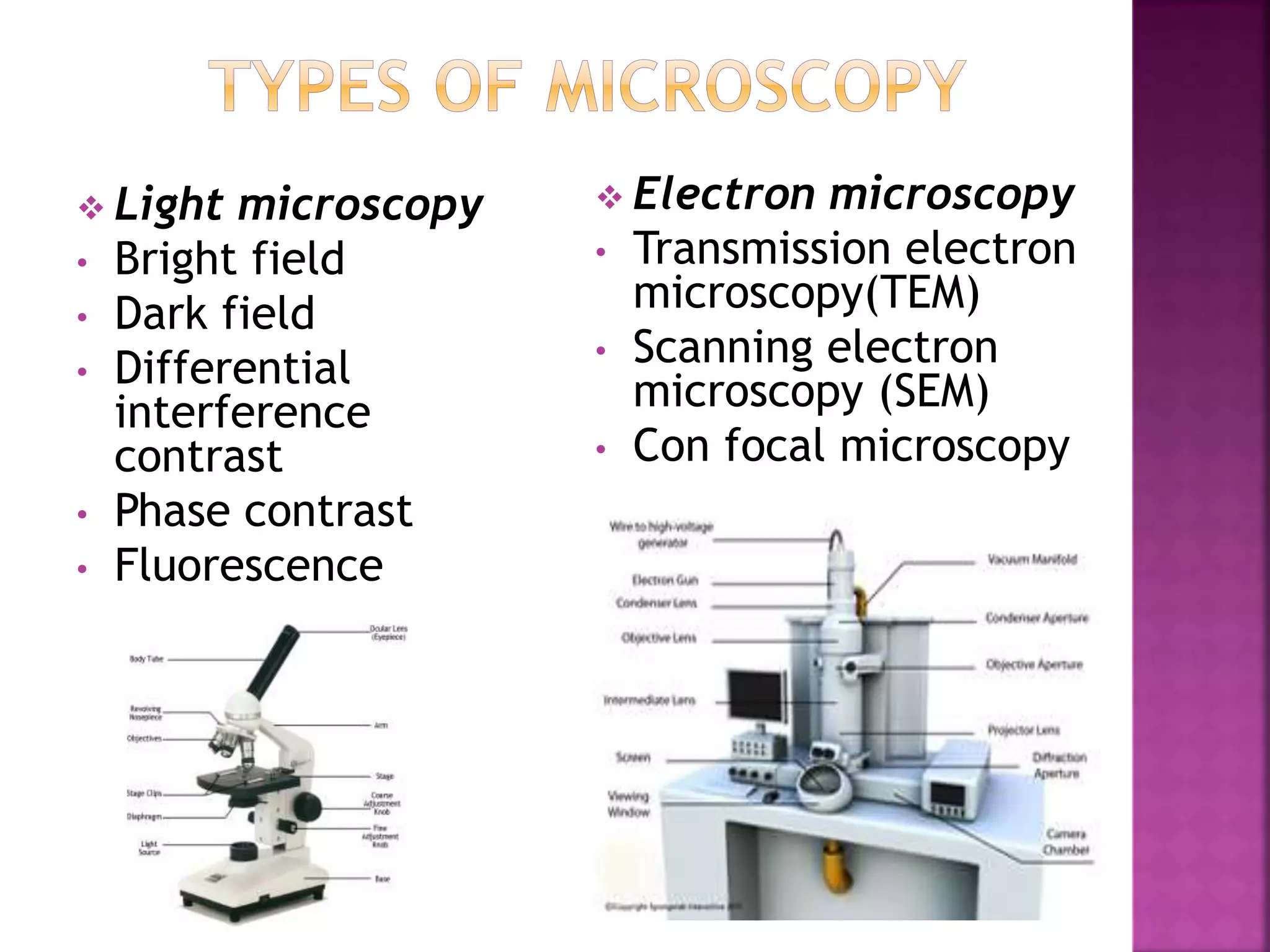
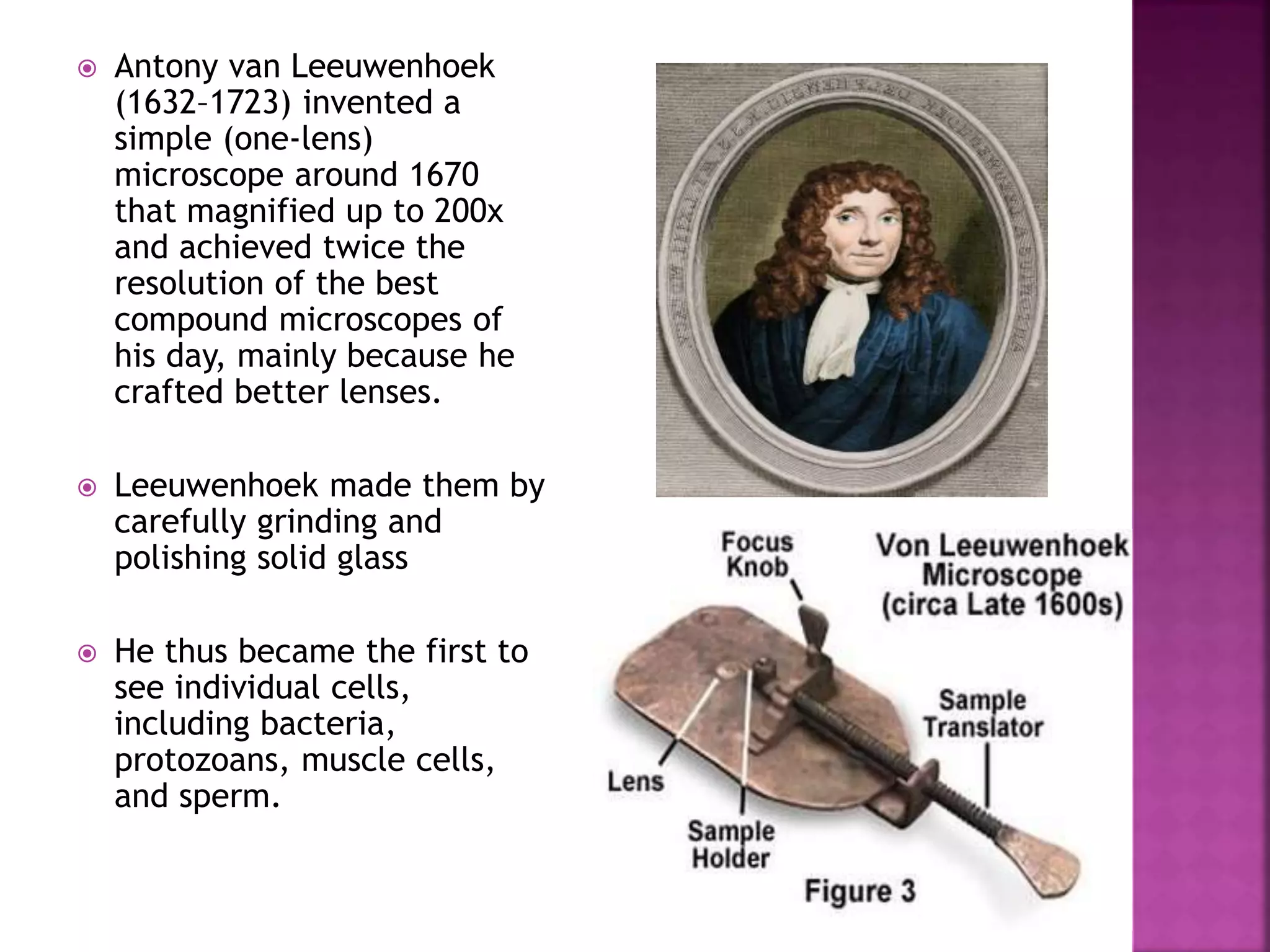
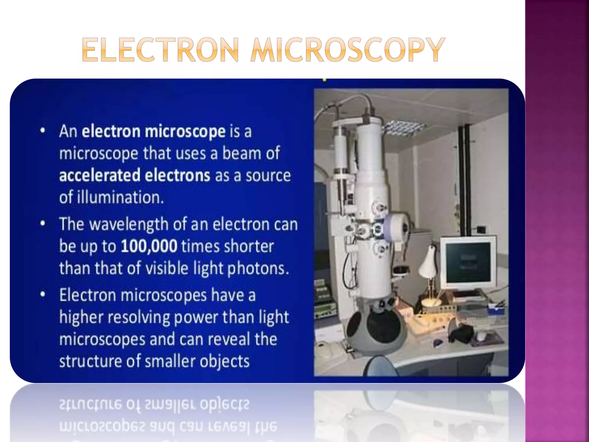
Microscopy is the technical field of using microscopes to view objects and areas of objects that cannot be seen with the naked eye. There are three well-known branches of microscopy: optical, electron, and scanning probe microscopy, along with the emerging field of X-ray microscopy.
2. Microscopy is the technical field of
using microscopes to view objects and areas of
objects that cannot be seen with the naked eye
(objects that are not within the resolution range of
the normal eye)
3. Light microscopy
• Bright field
• Dark field
• Differential
interference
contrast
• Phase contrast
• Fluorescence
Electron microscopy
• Transmission electron
microscopy(TEM)
• Scanning electron
microscopy (SEM)
• Con focal microscopy
4. A light microscope(LM) is an instrument that uses visible
light and magnifying lenses to examine small objects not
visible to the naked eye, or in finer detail than the naked
eye allows
Principle
5. Zacharias Jansen (1580–
1638) of Holland
invented a compound
light microscope, one
that used two lenses,
with the second lens
further magnifying the
image produced by the
first. His microscopes
were collapsing tubes
used like a telescope in
reverse, and produced
magnifications up to
nine times (9x)
6. Antony van Leeuwenhoek
(1632–1723) invented a
simple (one-lens)
microscope around 1670
that magnified up to 200x
and achieved twice the
resolution of the best
compound microscopes of
his day, mainly because he
crafted better lenses.
Leeuwenhoek made them by
carefully grinding and
polishing solid glass
He thus became the first to
see individual cells,
including bacteria,
protozoans, muscle cells,
and sperm.
7. Englishman Robert Hooke(1635–1703)
further refined the compound
microscope, adding such features as a
stage to hold the specimen, an
illuminator, and coarse and fine focus
controls.
8. • Eyepiece
• Barrel
• Turret
• Objective lenses
• Specimen (object) - not
part of the microscope
itself but in the light path
• Stage
• Condenser (lens)
• Iris diaphragm
• Sub stage
illumination (lighting)
• Stand / Base
9. Eyepiece
The eyepiece of an optical microscope produces a "real image", meaning that light actually
passes through the image - as opposed to simply appearing to have come from the image.
Note that the eyepiece magnifies the image produced by the objective lens (typically by x10), but
it does not resolve the image.
Barrel
The barrel is the upper part of the microscope and the part through which rays pass between the
eyepiece (above) and the objective lens (below). The barrel can usually be moved, i.e. adjusted
upwards or downwards, in order to focus the microscope.
"Arm" / "Neck"
The part of an optical microscope that arches backwards
Turret
The turret is the part of the light microscope that holds the objective lenses.
Objective lenses
Light microscopes are usually fitted with several objective lenses but only one objective is in use
(hence in the optical path) at any one time. The objective lens performs both magnification and
resolution of the object (specimen).
Specimen (object)
The specimen is the object of the optical system formed by the light microscope when
correctly set-up.
The specimen has usually been carefully prepared for viewing using a light microscope and must
be sufficiently thin and/or transparent enough to be effectively illuminated from the opposite side
from that of the eyepiece, i.e. samples on microscope slides are very thin because they are
illuminated from below yet sufficient light to form a good quality image must reach the eyepiece
which is above the slide.
10. Stage
The microscope stage holds the specimen in position at 90o to the light path.
That means perpendicular to an imaginary line between the centre of the
light source (below) and the centre of the eyepiece (above).
Condenser (lens)
The condenser is a lens that focuses light on to the specimen. Even
illumination is essential in order to obtain a clear and meaningful images.
This is usually a simple matter of the microscope manufacturer selecting an
appropriate condenser lens, which may not be adjustable by the user.
Iris diaphragm
In the same way as the iris of the eye, the iris diaphragm in the illumination
light path of light microscope controls the amount of light available to reach
the specimen, and therefore ultimately the eye of the person using the
microscope.
Sub stage illumination(lighting)
Location of light source: The only illumination of the specimen should be
from the sub stage position. Additional illumination from other, e.g. higher,
positions reduce the contrast in the final image which reduces the quality of
the image seen by the user.
Color of light source: "White" light, which is a combination of a wide range of
wavelengths, is frequently used but light of predominately shorter
wavelengths e.g. blue light enables a higher resolution image to be formed.
Stand / Base
The "stand" or "base" is not part of (within) the optical path but is an
important part of the outer mechanical structure of the microscope. As
demonstrated in the following microscope video demo, it is important to
support the base of a light microscope when carrying or moving it.
11.
12. Bright field microscopy
Dark field microscopy
Phase contrast microscopy
Differential interference contrast
Fluorescence microscopy
Con focal microscopy
13. Bright-field microscopy is the simplest of all the optical
microscopy illumination techniques
Sample illumination is transmitted (i.e., illuminated from
below and observed from above) white light, and contrast in
the sample is caused by attenuation of the transmitted light in
dense areas of the sample.
Bright-field microscopy is the simplest of a range of
techniques used for illumination of samples in light
microscopes, and its simplicity makes it a popular technique.
The typical appearance of a bright-field microscopy image is a
dark sample on a bright background, hence the name.
14. Example of bright field micrograph
Cross section of vascular tissue of
plant stem
Specimen of Cheek cells
15. Dark-field microscopy (dark-ground
microscopy) describes microscopy methods,
in both light microscopy which exclude the
un scattered beam from the image. As a
result, the field around the specimen (i.e.,
where there is no specimen to scatter the
beam) is generally dark.
It is the technique used to observe unstained
specimen /samples causing them to appear
brightly lit against dark ,almost purely ,dark
,black background
16. The steps are illustrated in the figure where
an inverted microscope is used.
Light enters the microscope for illumination
of the sample.
A specially sized disc, the patch stop (see
figure), blocks some light from the light
source, leaving an outer ring of
illumination. A wide phase annulus can also
be reasonably substituted at low
magnification.
The condenser lens focuses the light
towards the sample.
The light enters the sample. Most is directly
transmitted, while some is scattered from
the sample.
The scattered light enters the objective
lens, while the directly transmitted
light simply misses the lens and is not
collected due to a direct-illumination
block (see figure).
Only the scattered light goes on to produce
the image, while the directly transmitted
light is omitted
17.
18.
19.
20. Phase-contrast microscopes use refraction and
interference caused by structures in a specimen to
create high-contrast, high-resolution images without
staining.
It is the oldest and simplest type of microscope
that creates an image by altering the wavelengths of
light rays passing through the specimen.
More generally, structures that differ in features
such as refractive index will differ in levels of
darkness
Thicker part held /absorb more light than thinner
part
21.
22.
23. Differential interference contrast (DIC) microscopes (also
known as Nomarski optics) are similar to phase-contrast
microscopes in that they use interference patterns to
enhance contrast between different features of a specimen.
In a DIC microscope, two beams of light are created in
which the direction of wave movement (polarization) differs.
Once the beams pass through either the specimen or
specimen-free space, they are recombined and effects of
the specimens cause differences in the interference patterns
generated by the combining of the beams.
This results in high-contrast images of living organisms with
a three-dimensional appearance.
These microscopes are especially useful in distinguishing
structures within live, unstained specimens.
24.
25. (DIC)DIFFERENTIAL INTERFERENCE
CONTRAST
A DIC image of Fonsecaea pedrosoi
grown on modified Leonian’s agar.
This fungus causes
chromoblastomycosis, a chronic skin
infection common in tropical and
subtropical climates.
26.
27. A fluorescence microscope uses fluorescent chromophores
called fluorochromes, which are capable of absorbing energy from
a light source and then emitting this energy as visible light.
Fluorochromes include naturally fluorescent substances (such as
chlorophylls) as well as fluorescent stains that are added to the
specimen to create contrast
Certain chemicals produces visible light when they are illuminated
in uv light the effect is called fluorescence and
phosphorescence.
The microscope transmits an excitation light, of a short
wavelength, such as ultraviolet or blue light, toward the specimen;
the chromophores absorb the excitation light and emit visible
light with longer wavelengths.
The excitation light is then filtered out (in part because
ultraviolet light is harmful to the eyes) so that only visible light
passes through the ocular lens. This produces an image of the
specimen in bright colors against a dark background.
28.
29. (a) A direct immunofluorescent
stain is used to visualize
Neisseria gonorrhoeae, the
bacterium that causes
gonorrhea
(b) An indirect immunofluorescent
stain is used to visualize larvae of
Schistosoma mansoni, a parasitic
worm that causes schistosomiasis, an
intestinal disease common in the
tropic
30. light microscopy create an image that is maximally focused
at a single distance from the observer (the depth, or z-
plane), a confocal microscope uses a laser to scan multiple
z-planes successively.
This produces numerous two-dimensional, high-resolution
images at various depths, which can be constructed into a
three-dimensional image by a computer.
As with fluorescence microscopes, fluorescent stains are
generally used to increase contrast and resolution.
Image clarity is further enhanced by a narrow aperture
that eliminates any light that is not from the z-plane.
Confocal microscopes are thus very useful for examining
thick specimens such as biofilms, which can be examined
alive and unfixed
31.
32. Confocal microscopy can be used to visualize structures
such as this roof-dwelling cyanobacterium biofilm.
33. Phase contrast microscopy
was first described by
Dutch physicist Frits
Zernike in 1934
Differential interference
contrast microscopy was
invented by polish
physicist Georges (Jerzy)
Nomarski (1919-1997)
British scientist ,Sir
George .G.Stokes first
described fluorescence
microscopy in 1852 and
coined the term
37. The electron microscope produces high resolution detail by
using electrons instead of light to form images.
The extremely short wavelength and focus ability of
electron beams are responsible for the theoretically high
resolving power of electron microscopes.
The increased resolution allows a functional magnification
of up to 1,000,000× for the observation of fine structure
and detail.
In the electron microscope, an electron gun aims a beam
of electrons at a specimen placed in a vacuum sample
chamber. A series of coiled electromagnets are used to
focus the beam.
As in light microscopy, poor contrast is a problem in
electron microscopes, so samples are often stained to
increase contrast. Images produced in the electron
microscope are in shades of gray, although computerized
color may be added in some scopes.
38. TEM ( transmission electron microscopy
SEM ( scanning electron microscopy )
39. For electrons to pass through the specimen in a
TEM, the specimen must be extremely thin (20–100
nm thick).
The image is produced because of varying opacity
in various parts of the specimen. This opacity can
be enhanced by staining the specimen with
materials such as heavy metals, which are electron
dense.
TEM requires that the beam and specimen be in a
vacuum and that the specimen be very thin and
dehydrated.
Dense region in specimen scatter more electron
and appear darker
Image is focused on photographic film.
Transmitted electrons (those do not scatter ) are
used to produce image.
40. A vacuum system in which electrons travel .
An electron emission source for generation of the electron stream,
A series of electromagnetic lenses,
Electrostatic plates.
The latter two allow the operator to guide and manipulate the beam as
required. Also required is a device to allow the insertion into, motion
within, and removal of specimens from the beam path
41.
42. Uses electrons reflected from the surface of a specimen
to create image.
Produces a detailed 3-dimensional image of
specimen’s surface features.
Electron beam passing through the specimen or
transmitted by the specimen, interaction of electrons of
beam with the surface of specimen causes emission of
secondary electrons from the surface of the specimen.
The number of electrons produced from the specimen
as well as the direction in which scattering occur
depends on topography of surface.
43. Scanning of surface of
specimen with electrons
should be synchronized
with projection of beam
on television screen so
that form same image on
the screen.
Samples to be examined
should be coated with
metal that generate
primary electrons and
also produces secondary
electrons.
SEM helps in taking
images from different
angles and provides
additional information
on size, shape and
organization of specimen.
44. Micrograph of Trichome through scanning electron microscope
45.
46. (a) A transmission electron microscope (TEM). (b) A
scanning electron microscope (SEM).
47. These schematic illustrations compare the
components of transmission electron
microscopes and scanning electron
microscopes.
48. (a) This TEM image of cells in a biofilm shows well-defined internal structures of the
cells because of varying levels of opacity in the specimen. (b) This color-enhanced SEM
image of the bacterium Staphylococcus aureus illustrates the ability of scanning
electron microscopy to render three-dimensional images of the surface structure of
cells.
49.
50. Electron microscopes use magnets to focus electron beams similarly to
the way that light microscopes use lenses to focus light.
51. preparation takes usually few minutes to Specimen preparation takes usually takes
ad specimen may be seen . Only Dead or Dried specimens are seen
r, Objective and eye piece lenses are made
ses .
. All lenses are electromagnetic
resolving power (0.25µm to 0.3µm). It has high resolving power (0.001µm), ab
times higher than light microscope .
agnification of 500X to 1500X. It has a magnification of 100,000X to 300,0
t is 5µm or thicker. The object is 0.1µm or thinner.
olored Image is Black and White.
not required . Vacuum is essential for its operation .
o need of high voltage electricity High voltage electric current is required (5
and above).
no cooling system It has a cooling system to take out heat ge
high electric current.
s not used. Tungsten filament is used to produce elect
risk is absent. There is risk of radiation leakage.
is stained by colored dyes. Specimen is coated with heavy metals in o
reflect electrons.
52.
53. Characteristic Optical Electron
Illuminating beam Light beam Electron beam
Wavelength 7500 Å (visible) 0.086 Å (20 kV)
2000 Å (ultraviolet) 0.037 Å (100 kV)
Medium Atmosphere Vacuum
Lens Glass lens Electrostatic lens
Resolving power 2000 Å 3 Å
Magnification Up to 2000× Up to 1,000,000×
Focusing Mechanical Electrical
Viable specimen Yes No
Specimen requires
staining or treatment
Yes/no Always
Colored image
produced
Yes No
58. A microtome (from the Greek mikros, meaning "small", and temnein,
meaning "to cut") is a tool used to cut extremely thin slices of material,
known as sections.
Important in science, microtomes are used in microscopy, allowing for
the preparation of samples for observation under
transmitted light or electron radiation.
Microtomes use steel, glass, or diamond blades depending upon the
specimen being sliced and the desired thickness of the sections being cut.
Steel blades are used to prepare sections of animal or plant tissues
for light microscopy histology.
Glass knives are used to slice sections for light microscopy and to slice
very thin sections for electron microscopy.
Industrial grade diamond knives are used to slice hard materials such as
bone, teeth and plant matter for both light microscopy and for electron
microscopy.
Gem quality diamond knives are used for slicing thin sections for electron
microscopy.