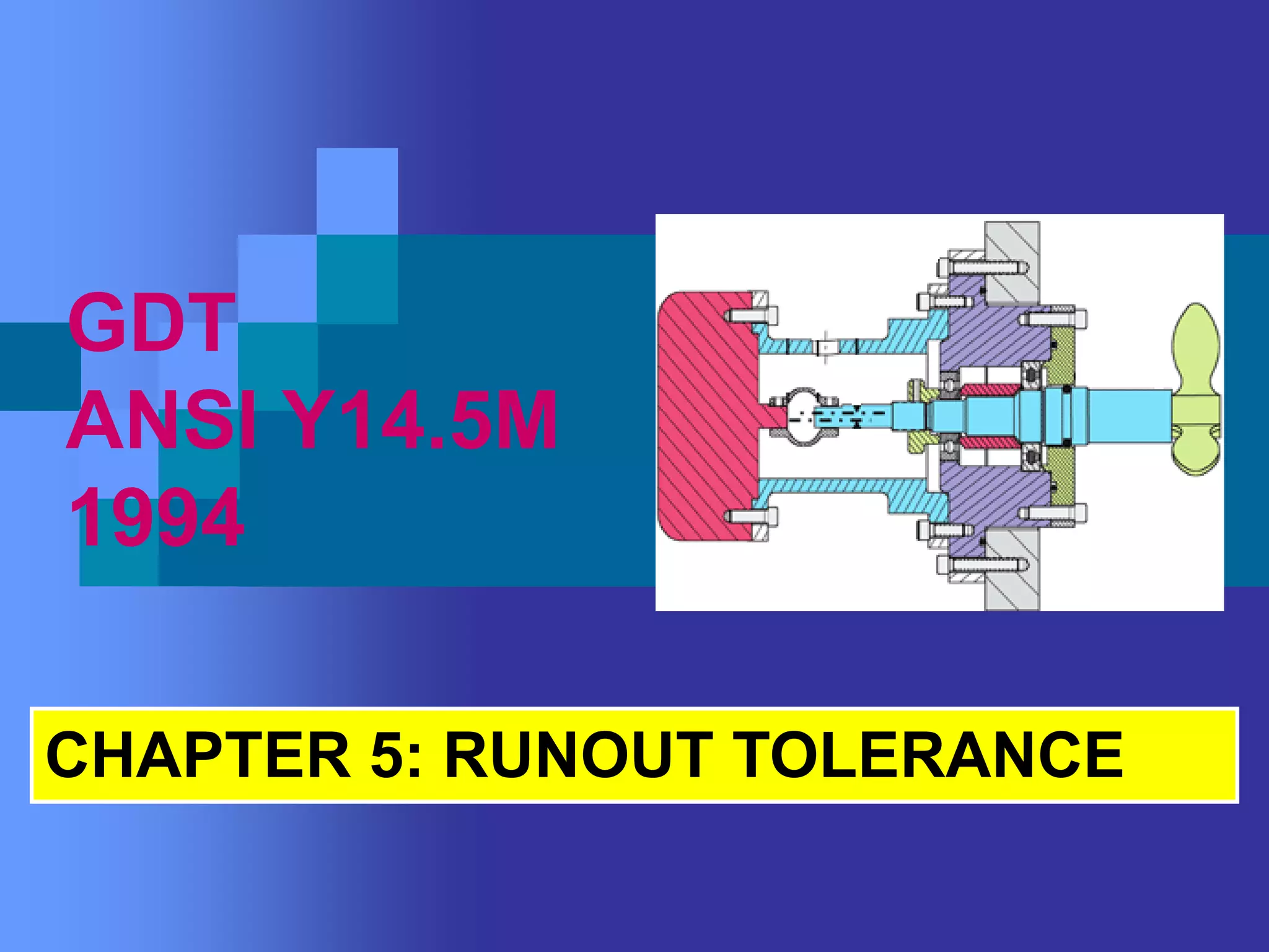
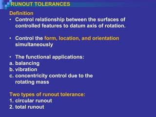
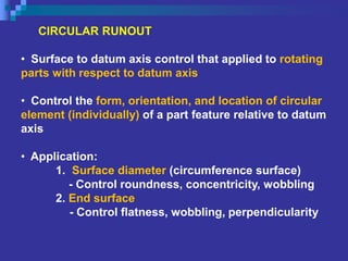
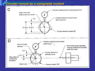
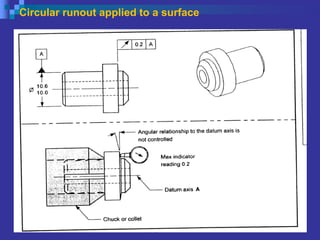
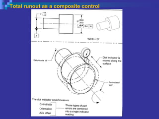
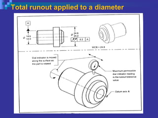
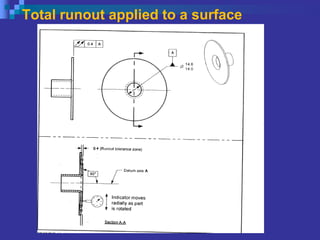
GDT
ANSI Y14.5M
1994
CHAPTER 5: RUNOUT TOLERANCE
Objective:
 1. Interpret the circular runout control
 2. Interpret the total runout control.
RUNOUT TOLERANCES
Definition
• Control relationship between the surfaces of
controlled features to datum axis of rotation.
• Control the form, location, and orientation
simultaneously
• The functional applications:
a. balancing
b. vibration
c. concentricity control due to the
rotating mass
Two types of runout tolerance:
1. circular runout
2. total runout
CIRCULAR RUNOUT
• Surface to datum axis control that applied to rotating
parts with respect to datum axis
• Control the form, orientation, and location of circular
element (individually) of a part feature relative to datum
axis
• Application:
1. Surface diameter (circumference surface)
- Control roundness, concentricity, wobbling
2. End surface
- Control flatness, wobbling, perpendicularity
Establishing a datum axis for runout
Circular runout tolerance zone
Circular runout as a composite control
Circular runout applied to a diameter
Circular runout applied to a surface
TOTAL RUNOUT
• Control the entire surface elements to datum axis
that is applied to rotating part
• Control the form, orientation, and location of a part
feature simultaneously
• Application
i. Cylindrical Surface (circumference surface)
- control roundness, cylindricality, angularity,
concentricity, wobbling of entire surface diameter
ii. End surface
- control flatness, wobbling, perpendicularity
of entire end surface
Total runout as a composite control
Total runout applied to a diameter
In this application, thefollowing conditions
apply:
The diameter must meet its size
requirements.
The WCB is affected (24.6 + 0.2 = 24.8).
The runout control applies RFS.
The runout applies simultaneously to all
elements of the diameter.
The tolerance zone is two coaxial cylinders
0.2 apart.
The maximum possible axis offset is 0.1.
Total runout applied to a surface
The runout control applies RFS
The runout applies to all elements of the surface
simultaneously.
The shape of the tolerance zone is two parallel
planes perpendicular to the datum axis.
The runout symbol controls the angular
relationship (orientation) of the surface to the
datum axis.
The runout control also limits the flatness of the
surface.

GDT CHAPTER 5- Runout Tol.pdf

  • 1.
  • 2.
    Objective:  1. Interpretthe circular runout control  2. Interpret the total runout control.
  • 3.
    RUNOUT TOLERANCES Definition • Controlrelationship between the surfaces of controlled features to datum axis of rotation. • Control the form, location, and orientation simultaneously • The functional applications: a. balancing b. vibration c. concentricity control due to the rotating mass Two types of runout tolerance: 1. circular runout 2. total runout
  • 4.
    CIRCULAR RUNOUT • Surfaceto datum axis control that applied to rotating parts with respect to datum axis • Control the form, orientation, and location of circular element (individually) of a part feature relative to datum axis • Application: 1. Surface diameter (circumference surface) - Control roundness, concentricity, wobbling 2. End surface - Control flatness, wobbling, perpendicularity
  • 5.
    Establishing a datumaxis for runout
  • 6.
  • 7.
    Circular runout asa composite control
  • 8.
    Circular runout asa composite control
  • 9.
  • 10.
  • 11.
    TOTAL RUNOUT • Controlthe entire surface elements to datum axis that is applied to rotating part • Control the form, orientation, and location of a part feature simultaneously • Application i. Cylindrical Surface (circumference surface) - control roundness, cylindricality, angularity, concentricity, wobbling of entire surface diameter ii. End surface - control flatness, wobbling, perpendicularity of entire end surface
  • 12.
    Total runout asa composite control
  • 13.
    Total runout asa composite control
  • 14.
    Total runout appliedto a diameter
  • 15.
    Total runout appliedto a diameter In this application, thefollowing conditions apply: The diameter must meet its size requirements. The WCB is affected (24.6 + 0.2 = 24.8). The runout control applies RFS. The runout applies simultaneously to all elements of the diameter. The tolerance zone is two coaxial cylinders 0.2 apart. The maximum possible axis offset is 0.1.
  • 16.
  • 17.
    Total runout appliedto a surface The runout control applies RFS The runout applies to all elements of the surface simultaneously. The shape of the tolerance zone is two parallel planes perpendicular to the datum axis. The runout symbol controls the angular relationship (orientation) of the surface to the datum axis. The runout control also limits the flatness of the surface.