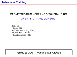
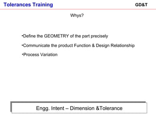
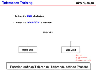
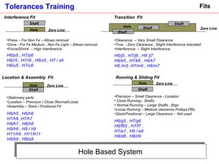
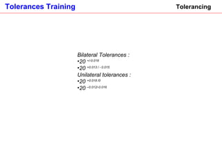
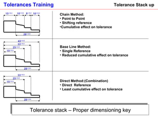
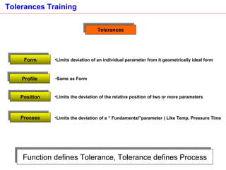
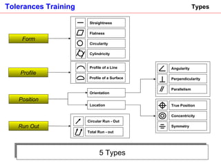
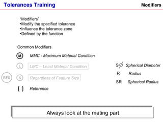
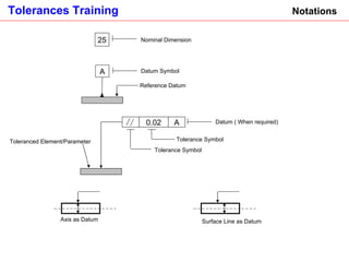
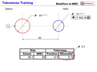
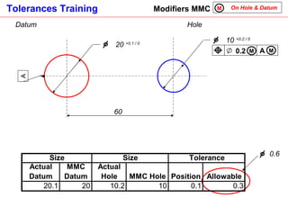
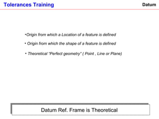
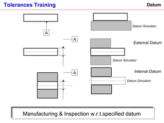
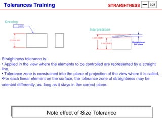
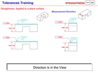
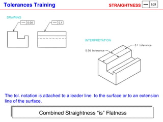
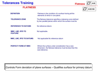
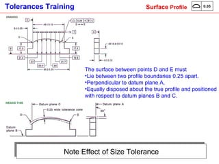
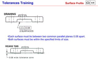
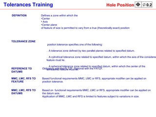
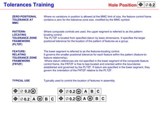
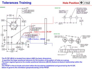
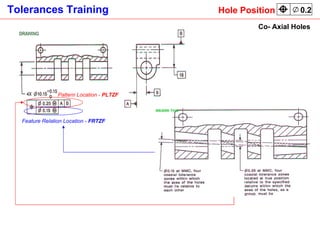
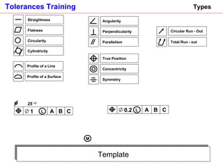
SlideShare a Scribd company logo
1 of 80
[object Object],[object Object],[object Object],[object Object],[object Object],[object Object]
Guide to GD&T– Variants Still Allowed GEOMETRIC DIMENSIONING & TOLERANCING ANSI Y14.5M – R1988 STANDARD ,[object Object],[object Object],[object Object],[object Object],[object Object]
Engg. Intent – Dimension &Tolerance GD&T ,[object Object],[object Object],[object Object],Whys?
Dimensioning ,[object Object],[object Object],Dimension Basic Size Function defines Tolerance, Tolerance defines Process Size Limit ,[object Object],[object Object],[object Object]
Hole Based System  Fits Transition  Fit  ,[object Object],[object Object],[object Object],H6/p5 , H7/p6  H6/r5 , H7/r6 , H6/s5 , H7 / s6 H6/u5 , H7/u6 ,[object Object],[object Object],[object Object],H6/h5 , H6/h6  H7/h6 ,H7/h7 H8/h7 , H8/h8 H9/h8 , H9 / h9 H11/h9 , H11/h11 H8/b9 , H8/a9  H6/j5 , H7/j6 , H8 /j7 H6/k5 , H7/k6 , H6/k7 H6 /m5 ,H7/m6 , H8/m7 H6/g5 , H7/g6  H6/f65 , H7/f7 ,  H7/e7 , H8 / e8 H8/d8 , H8/d9 Hole Zero Line Shaft Shaft Shaft ,[object Object],[object Object],[object Object],[object Object],[object Object],[object Object],[object Object],[object Object],Interference Fit  Shaft Hole Zero Line Location & Assembly  Fit  Shaft Hole Zero Line Running & Sliding Fit  Shaft Hole Zero Line
Tolerancing ,[object Object],[object Object],[object Object],[object Object],[object Object],[object Object]
Tolerance stack – Proper dimensioning key Tolerance Stack up  ,[object Object],[object Object],[object Object],[object Object],[object Object],[object Object],[object Object],[object Object],[object Object],[object Object],15 +/-0.2 10 +/-0.2 10 +/-0.2 8 +/-0.2 28 +/-0.6 43 +/-0.2 33 +/-0.2 15 +/-0.2 25 +/-0.2 28 +/-0.4 33 +/-0.2 15 +/-0.2 25 +/-0.2 28 +/-0.4
Function defines Tolerance, Tolerance defines Process Tolerances Form ,[object Object],Profile ,[object Object],Position ,[object Object],Process ,[object Object]
5 Types Types Form Straightness Flatness Circularity Cylindricity Profile Profile of a Line Profile of a Surface Position Orientation Location Angularity Perpendicularity Parallelism True Position Concentricity Symmetry Run Out Circular Run - Out Total Run - out
Always look at the mating part Modifiers ,[object Object],[object Object],[object Object],[object Object],M L RFS Common Modifiers MMC - Maximum Material Condition LMC – Least Material Condition S Regardless of Feature Size Reference  S SR R Radius Spherical Radius Spherical Diameter
Notations Reference Datum Datum Symbol Axis as Datum Surface Line as Datum Toleranced Element/Parameter 0.02 A Tolerance Symbol Tolerance Symbol Datum ( When required) A 25 Nominal Dimension
Feature Control Frame Position Tolerance Zone Symbol Shape of Tolerance Zone Size of Tolerance Zone Primary Datum Secondary Datum  Tertiary Datum  Material Condition Modifier Secondary Datum Material Condition Modifier B A 0.2 M C M
Function drives Modifiers  Modifiers E=mC 2 E=cM 2
Tolerance Zone does not Change Modifiers ,[object Object],[object Object],[object Object],[object Object],[object Object]
Process Control Size Vs Position LMC ,[object Object],[object Object],[object Object],[object Object],[object Object],25 20 12  +0.2 / - 0.1 B A 0.2 C L C B A
Process Control Size Boss Vs Hole LMC 25  +2   B A 1 C L B A 0.2 C L LMC – Boss & Hole  C B 12  - 0.5 A 75 60 25  12   Boss Tol. Zone  1  Hole Tol. Zone  0.2
Bonus Zone Modifiers ,[object Object],[object Object],[object Object],[object Object],[object Object],[object Object],[object Object],Eg; Position Tolerance of the hole increase as the hole size increases
Classic Case- Bell Crank & Sleeve Modifiers at MMC A A 0.02 M 25  0.00/-0.018   18  0.00 /-0.013   A A 0.02 M 25  0 .02/0.00   18  0.013/0.00
Modifiers MMC On Hole M Datum A 0.2 M Hole  60 10  +0.2 / 0 20  +0.1 / 0 A 0.4
Modifiers at MMC On Datum  M Datum Hole  A 0.2 M 60 10  +0.2 / 0 20  +0.1 / 0 A 0.3
Modifiers MMC On Hole & Datum  M Datum 0.2 M Hole  60 10  +0.2 / 0 20  +0.1 / 0 A A M 0.6
Datum Ref. Frame is Theoretical  Datum ,[object Object],[object Object],[object Object]
Manufacturing & Inspection w.r.t.specified datum  Datum External Datum Datum Simulator  Datum Simulator  Datum Simulator  Internal Datum  A A A
Controls Form of Cylindrical/Conical Surfaces- Applies to Entire Surface DEFINITION :  Straightness is a condition where the surface or an axis of an element is a straight line. ,[object Object],[object Object],[object Object],REFERENCE TO DATUMS :  No reference datum . MMC, LMC, RFS TO FEATURE :  Applicable if the tolerance applies to the axis or center plane of a feature or size.    Not applicable if the toleranced feature is a surface. MMC, LMC, RFS TO DATUMS :  No datum reference . PERFECT FORM AT MMC :  Applicable when the tolerance is applied to a surface.    "Perfect from at MMC not required"  may be specified. Especially useful when the part is subject to small deformations under its own weight or internal stresses.  STRAIGHTNESS  0.21
      Straightness: Applied to the Surface Cylinder ,[object Object],[object Object],[object Object],STRAIGHTNESS  0.21
Neck Bow Barrel STRAIGHTNESS  0.21
Cylinder Liner Tier 2 STRAIGHTNESS  0.21
Note effect of Size Tolerance  ,[object Object],[object Object],[object Object],[object Object],STRAIGHTNESS  0.21
Direction is in the View Straightness: Applied to a plane surface Measurement Direction STRAIGHTNESS  0.21
Combined Straightness “is” Flatness The tol. notation is attached to a leader line  to the surface or to an extension line of the surface.   STRAIGHTNESS  0.21
Controls Form deviation of plane surfaces – Qualifies surface for primary datum FLATNESS DEFINITION Flatness is the condition of a surface having all the elements of which in one plane. TOLERANCE ZONE The flatness tolerance specifies a tolerance zone defined by two parallel planes within which the surface must lie. REFERENCE TO DATUMS No reference datum. MMC, LMC, RFS TO FEATURE Not applicable. MMC, LMC, RFS TO DATUMS Not applicable.No reference datum PERFECT FORM AT MMC Where the surface under consideration has a size dimension, the flatness tolerance must be less than the size tolerance. Flatness 0.05 0.05/100
[object Object],[object Object],Flatness 0.05
Flatness – Primary Datum/Seat/Sealing face Flatness 0.05
Datum , Seat Definition Flatness 0.05
Defines Datum DEFINITION Circularity is a condition of a surface of revolution where  a.   (For a Cylindrical/Round feature other than a sphere,) all points of the surface intersected by any plane perpendicular to the axis are equidistant from that axis;  b.   For a sphere, all points of the surface intersected by any plane passing through a common center are equidistant from that center.  TOLERANCE ZONE A circularity tolerance specifies a tolerance zone bounded by two concentric circles within which each circular element of the surface must lie, and applies independently at any plane. REFERENCE TO DATUMS No reference datum. MMC, LMC, RFS TO FEATURE Not applicable. MMC, LMC, RFS TO DATUMS Not applicable.No reference datum PERFECT FORM AT MMC The circularity tolerance must be less than the size tolerance, except for parts subject to free state variation. CIRCULARITY/ROUNDNESS 0.05
The tolerance zone of circularity is expressed as the radial difference between two concentric circles   The circularity tolerance applies at each circular section of the diameter independently   CIRCULARITY/ROUNDNESS 0.05
CIRCULARITY/ROUNDNESS 0.05
“ Combined effect” of Straightness & Roundness DEFINITION Cylindricity is a condition of a surface of revolution in which all points of the surface are equidistant from a common axis. TOLERANCE ZONE A Cylindricity tolerance specifies a tolerance zone bounded by two concentric cylinders within which the surface must lie. REFERENCE TO DATUMS No reference datum. MMC, LMC, RFS TO FEATURE Not applicable. MMC, LMC, RFS TO DATUMS Not applicable.No reference datum PERFECT FORM AT MMC Applicable. Cylindricity tolerances cannot violate the maximum boundary of perfect form at MMC of the associated size tolerance. Application Functional applications that require a true cylinder such as rotating shaft journal and bearing diameters, pistons and piston bores. Also used to qualify datum diameters. Used only when the size tolerance does not provide appropriate form control. Cylindricity 0.03
[object Object],[object Object],Cylindricity 0.03
Cylindricity 0.03
DEFINITION A profile is the outline of an object in a given plane. The profile tolerance specifies a uniform boundary along the true profile within which the elements of the line must lie. It is used to control form or combinations of size, form, orientation, and location. TOLERANCE ZONE The tolerance zone established by the profile of a line tolerance is two-dimensional, extending along the length of the considered feature. This applies to the profiles of parts having a varying cross section, such as the tapered wing of an aircraft, or to random cross sections of parts where it is not desired to control the entire surface of the feature as a single entity.  REFERENCE TO DATUMS In most cases, profile of line tolerance requires reference to datum in order to provide proper orientation, location, or both, of the profile. With profile of a line tolerance, datum may be used under some circumstances but would not be used when the only requirement is the profile shape taken cross section by cross section. An example is the shape of a continuous extrusion.  MMC, LMC, RFS TO FEATURE The specified tolerance can only apply on an RFS basis.  MMC, LMC, RFS TO DATUMS The datum reference can only apply on an RFS basis.  Application Typically used to control profiles of parts having a varying cross section.  Line  Profile 0.1 0.1 A
Effect of Size Form Tolerance  Line  Profile ,[object Object],[object Object],[object Object]
DEFINITION A profile is the outline of an object in a given plane. The profile tolerance specifies a uniform boundary along the true profile within witch the elements of the line must lie. It is used to control form or combinations of size, form, orientation, and location.  TOLERANCE ZONE The tolerance zone established by the profile of a surface tolerance is three-dimensional, extending along the length and width (or circumference) of the considered feature or features.  REFERENCE TO DATUMS Profile of surface tolerance requires reference to datum in order to provide proper orientation, location, or both, of the profile.  With profile of a line tolerance, datum may be used in some circumstances but would not be used when the only requirement is the profile shape.  MMC, LMC, RFS TO FEATURE The specified tolerance can only apply on an RFS basis.  MMC, LMC, RFS TO DATUMS The datum reference can only apply on an RFS basis.  TYPICAL USE Typically used to control parts with a surface of revolution, or castings with surfaces defined by profile tolerances . Surface  Profile 0.05 A 0.05
Note Effect of Size Tolerance ,[object Object],[object Object],[object Object],[object Object],Surface  Profile 0.05
Gen 1 Bell Crank  Surface  Profile 0.05
[object Object],[object Object],Surface  Profile 0.05
Position Tolerance
DEFINITION ,[object Object],[object Object],[object Object],[object Object],[object Object],TOLERANCE ZONE A position tolerance specifies one of the following:  1.  A tolerance zone defined by two parallel planes related to specified datum. 2.  A cylindrical tolerance zone related to specified datum, within which the axis of the considered feature must lie. 3.  A spherical tolerance zone related to specified datum, within which the center of the considered feature must lie. REFERENCE TO DATUMS Obligatory with the PLTZF. Optional with the FRTZF. MMC, LMC, RFS TO FEATURE Based functional requirements MMC, LMC or RFS, appropriate modifier can be applied on position tolerance.  MMC, LMC, RFS TO DATUMS Based on  functional requirements MMC, LMC or RFS, appropriate modifier can be applied on the datum axis.  Application of MMC, LMC and RFS is limited to features subject to variations in size. Hole Position 0.2
ZERO POSITIONAL TOLERANCE AT MMC Where no variations in position is allowed at the MMC limit of size, the feature control frame contains a zero for the tolerance zone size, modified by the MMC symbol. PATTERN-LOCATING TOLERANCE ZONE FRAMEWORK (PLTZF) Where composite controls are used, the upper segment is referred to as the pattern-locating control.  The PLTZF is located from specified datum by basic dimensions. It specifies the larger positional tolerance for the location of the pattern of features as a group. FEATURE-RELATING TOLERANCE ZONE FRAMEWORK (FRTZF) The lower segment is referred to as the features-locating control.  It governs the smaller positional tolerance for each feature within the pattern (feature-to-feature relationship). Where datum references are not specified in the lower segment of the composite feature control frame, the FRTZF is free to bee located and oriented within the boundaries established and governed by the PLTZF. If datum are specified in the lower segment, they govern the orientation of the FRTZF relative to the PLTZF. TYPICAL USE Typically used to control the location of features in assembly. B A 0.2 C M B A 0.2 C M B A 0.2 C M M 0.2   M Hole Position 0.2
The PLTZF (Ø0.8) is located from datum (ABC) by basic dimensions. It specifies the larger positional tolerance for the location of the pattern of holes as a group. The lower segment governs the smaller positional tolerance (Ø0.25) (feature-to-feature relationship) within the pattern . The FRTZF is free to locate and orient within the boundaries established and governed by the PLTZF. Datum A governs the orientation (perpendicularity) of the FRTZF .  Pattern Location -  PLTZF Feature Realtion -  FRTZF Hole Position 0.2
Co- Axial Holes Pattern Location -  PLTZF Feature Relation Location -  FRTZF Hole Position 0.2
Gen 1 Bell Crank ,[object Object],[object Object],[object Object],Hole Position 0.2
Hole Position 0.2
DEFINITION The median points of all diametrically opposed elements of a surface of revolution lie on the  same axis (or center point) of a datum feature.  TOLERANCE ZONE A concentricity tolerance is a Cylindrical (or spherical) tolerance zone whose axis (or center point) coincides with the axis (or center point) of the datum feature(s).  REFERENCE TO DATUMS One datum feature (axis or center point). APPLICABILITY OF MMC, LMC, RFS TO FEATURE The specified tolerance can only apply on an RFS basis.  APPLICABILITY OF MMC, LMC, RFS TO DATUMS The datum reference can only apply on an RFS basis. TYPICAL USE Typically used to control ……….. Concentricity 0.04 A
Position Tolerance  Concentricity ,[object Object],[object Object],[object Object]
Use Either as Datum Position Tolerance  Concentricity
Use a Spigot Locator  Position Tolerance  Concentricity
DEFINITION The median points of all opposed or correspondingly-located elements of two or more feature surface lie in the same axis or center plane of a datum feature.  TOLERANCE ZONE A symmetry tolerance is two parallel planes whose axis (or center plane) coincides with the axis (or center plane) of the datum feature. REFERENCE TO DATUMS One datum feature (center plane). APPLICABILITY OF MMC, LMC, RFS TO FEATURE The specified tolerance can only apply on an RFS basis. APPLICABILITY OF MMC, LMC, RFS TO DATUMS The datum reference can only apply on an RFS basis. Symmetry 0.05 A
[object Object],[object Object],[object Object],Symmetry 0.05 A
Gen1 Bell Crank Symmetry 0.05 A
Position Tolerance  Angularity DEFINITION Condition of a surface, center plane, or axis at a specified angle from a datum plane or axis. TOLERANCE ZONE A angularity tolerance specifies one of the following:  1.       A tolerance zone defined by two parallel planes at the specified basic angle from one or more datum planes or axis, within which the surface or center plane of the considered feature must lie. 2.       A tolerance zone defined by two parallel planes at the specified basic angle from one or more datum planes or axis, within which the axis ot the considered feature must lie. 3.       A cylindrical tolerance zone at the specified basic angle from one or more datum planes or axis, within which the axis of the considered feature must lie. 4.       A tolerance zone defined by two parallel lines at the specified basic angle from one or more datum planes or axis, within which the line element of the surface must lie. REFERENCE TO DATUMS One or more datum features. Relation to more than one datum feature is specified to stabilize the tolerance zone in more then one direction. MMC, LMC, RFS TO FEATURE Based on functional requirements MMC, LMC or RFS, appropriate modifier can be applied on angularity tolerance.  Application  of MMC, LMC and RFS is limited to features subject to variations in size. MMC, LMC, RFS TO DATUMS If the functional requirements of some applications require MMC, LMC or RFS, appropriate modifier can be applied on the datum axis. Application of MMC, LMC and RFS is limited to features subject to variations in size. PERFECT ANGULARITY AT MMC Where no variations of angularity at MMC size limit of feature, the feature control frame contains a zero for the tolerance, modified by the symbol for MMC. TYPICAL USE Typically used to control orientation between planes surfaces.
Position Tolerance  Angularity ,[object Object],[object Object],[object Object],Angularity : Applied to Cylindrical Feature
Position Tolerance  Angularity ,[object Object],[object Object],[object Object],Angularity : Applied to Plane Surface
Position Tolerance  Perpendicularity DEFINITION Condition of a surface, center plane, or axis at a right angle to a datum plane or axis. TOLERANCE ZONE 1.       A tolerance zone defined by tow parallel planes perpendicular to a datum plane or axis, within which the surface or center plane of the considered feature must lie. 2.       A tolerance zone defined by two parallel planes perpendicular to a datum axis, within which the axis ot the considered feature must lie. 3.       A cylindrical tolerance zone perpendicular to a datum plane, within which the axis of the considered feature must lie. 4.       A tolerance zone defined by two parallel lines perpendicular to a datum plane or axis, within which the line element of the surface must lie. REFERENCE TO DATUMS One or more datum features. Relation to more than one datum feature is specified to stabilize the tolerance zone in more then one direction. MMC, LMC, RFS TO FEATURE Based on the functional requirement  MMC, LMC or RFS, appropriate modifier can be applied on perpendicularity tolerance.  Application of MMC, LMC and RFS is limited to features subject to variations in size. MMC, LMC, RFS TO DATUMS Based on functional requirements MMC, LMC or RFS, appropriate modifier can be applied on the datum axis.  Application of MMC, LMC and RFS is limited to features subject to variations in size.. PERFECT PEPENDICULARITY AT MMC Where no variations of perpendicularity at MMC size limit of feature, the feature control frame contains a zero for the tolerance, modified by the symbol for MMC.
Perpendicularity ,[object Object],[object Object],Perpendicularity : Applied to Plane Surface
Perpendicularity : Applied to Cylindrical Feature ,[object Object],[object Object],[object Object],Perpendicularity
 
100
Position Tolerance  Parallelism DEFINITION Condition of a surface, center plane, equidistant at all points from a datum plane; or axis and equidistant along its length from one or more datum planes or a datum axis. TOLERANCE ZONE A parallelism tolerance specifies one of the following:  1.       A tolerance zone defined by tow parallel planes parallel to a datum plane or axis, within which the surface or center plane of the considered feature must lie. 2.       A tolerance zone defined by two parallel planes parallel to a datum axis, within which the axis ot the considered feature must lie. 3.       A cylindrical tolerance zone parallel to a datum plane, within which the axis of the considered feature must lie. 4.       A tolerance zone defined by two parallel lines parallel to a datum plane or axis, within which the line element of the surface must lie. REFERENCE TO DATUMS One or more datum features. Relation to more than one datum feature is specified to stabilize the tolerance zone in more then one direction. MMC, LMC, RFS TO FEATURE Based on functional requirements MMC, LMC or RFS, appropriate modifier can be applied on parallelism tolerance.  Application of MMC, LMC and RFS is limited to features subject to variations in size.  MMC, LMC, RFS TO DATUMS Based on functional requirements  MMC, LMC or RFS, appropriate modifier can be applied on the datum axis.  Application of MMC, LMC and RFS is limited to features subject to variations in size.. PERFECT PARALLELISM AT MMC Where no variations of parallelism at MMC size limit of feature, the feature control frame contains a zero for the tolerance, modified by the symbol for MMC.
Position Tolerance  Parallelism ,[object Object],[object Object],[object Object],Parallelism : Applied to Plane Surface
Position Tolerance  Parallelism
Parallelism : Applied to Cylindrical Feature ,[object Object],[object Object],[object Object],Position Tolerance  Parallelism
Position Tolerance  Run-out DEFINITION Runout is a composite tolerance used to control the functional relationship of one or more features of a part to a datum axis. The types of features controlled by runout tolerance include those surfaces constructed around a datum axis and those constructed at right angles to a datum axis.  TOLERANCE ZONE Each considered feature must be within its runout tolerance when the part is rotated about the datum axis. The tolerance specified for a controlled surface is the total tolerance or full indicator movement (FIM).  REFERENCE TO DATUMS One or more datum features. Relation to more than one datum feature is specified to stabilize the tolerance zone in more then one direction. APPLICABILITY OF MMC, LMC, RFS TO FEATURE The specified tolerance can only apply on an RFS basis. APPLICABILITY OF MMC, LMC, RFS TO DATUMS The specified datum can only apply on an RFS basis. TYPICAL USE Typically used to control circularity and concentricity simultaneously.
Position Tolerance  Run-out Run-Out: Circular / Radial Run- Out At any measuring position, each circular element of these surfaces must be within the specified run-out tolerance (0.02 mm FIM) when the part is rotated 360º about the datum axis with the indicator fixed in a position normal to the true geometric shape.
Run-Out: (Circular / Radial) Total Indicated Reading The entire surface must lie with the specified total run-out tolerance zone (0.02 mm FIM) When the part is rotated 360º about the datum axis with the indicator placed at every location along the surface in a position normal to the true geometric shape without reset of the indicator
Run-Out: (Circular / Radial) Total Indicated Reading
Run-Out: Face- Total Indicated Reading- Example
 
Building Blocks
Template Types M Straightness Flatness Circularity Cylindricity Profile of a Line Profile of a Surface Angularity Perpendicularity Parallelism Concentricity True Position Symmetry Circular Run - Out Total Run - out 25  +2   B A 1 C L B A 0.2 C L

More Related Content

What's hot

Fits and tolerances in engineering
Fits and tolerances in engineeringFits and tolerances in engineering
Fits and tolerances in engineeringPrantik Chowdhury
 
Fundamentals of GD&T-1.pdf
Fundamentals of GD&T-1.pdfFundamentals of GD&T-1.pdf
Fundamentals of GD&T-1.pdfMuzzammil12
 
Engineering Metrology : System of Limits and Fits
Engineering Metrology : System of Limits and FitsEngineering Metrology : System of Limits and Fits
Engineering Metrology : System of Limits and FitsUnimetry Technology
 
Basic Geometrical Dimensioning & Tolerancing Tranning
Basic Geometrical Dimensioning  & Tolerancing TranningBasic Geometrical Dimensioning  & Tolerancing Tranning
Basic Geometrical Dimensioning & Tolerancing TranningTimothy Wooi
 
Geometric Dimensioning & Tolerancing
Geometric Dimensioning & TolerancingGeometric Dimensioning & Tolerancing
Geometric Dimensioning & TolerancingAnubhav Singh
 
Limit, fit, tolerance
Limit, fit, toleranceLimit, fit, tolerance
Limit, fit, toleranceSayyed Raza
 
Limits fits tolerance and surface roughness
Limits fits tolerance and surface roughnessLimits fits tolerance and surface roughness
Limits fits tolerance and surface roughnessVaibhav Pardeshi
 
Geometric Dimensioning and Tolerancing
Geometric Dimensioning and TolerancingGeometric Dimensioning and Tolerancing
Geometric Dimensioning and TolerancingUtsav Patel
 
Introduction to Geometric Dimensioning and Tolerancing (GD&T)
Introduction to Geometric Dimensioning and Tolerancing (GD&T)Introduction to Geometric Dimensioning and Tolerancing (GD&T)
Introduction to Geometric Dimensioning and Tolerancing (GD&T)Kapil Mukund
 

What's hot (20)

Gd&t
Gd&tGd&t
Gd&t
 
Fits and tolerances in engineering
Fits and tolerances in engineeringFits and tolerances in engineering
Fits and tolerances in engineering
 
GD&T
GD&TGD&T
GD&T
 
Limits, fits and tolerances
Limits, fits and tolerancesLimits, fits and tolerances
Limits, fits and tolerances
 
GD&T saravanan kulasekaran 27.06.16
GD&T saravanan kulasekaran 27.06.16GD&T saravanan kulasekaran 27.06.16
GD&T saravanan kulasekaran 27.06.16
 
Limits, fits, tolerance
Limits, fits, toleranceLimits, fits, tolerance
Limits, fits, tolerance
 
Fundamentals of GD&T-1.pdf
Fundamentals of GD&T-1.pdfFundamentals of GD&T-1.pdf
Fundamentals of GD&T-1.pdf
 
Limits,fits and tolerances
Limits,fits and tolerancesLimits,fits and tolerances
Limits,fits and tolerances
 
Engineering Metrology : System of Limits and Fits
Engineering Metrology : System of Limits and FitsEngineering Metrology : System of Limits and Fits
Engineering Metrology : System of Limits and Fits
 
Limits fits
Limits fitsLimits fits
Limits fits
 
Basic Geometrical Dimensioning & Tolerancing Tranning
Basic Geometrical Dimensioning  & Tolerancing TranningBasic Geometrical Dimensioning  & Tolerancing Tranning
Basic Geometrical Dimensioning & Tolerancing Tranning
 
Geometric Dimensioning & Tolerancing
Geometric Dimensioning & TolerancingGeometric Dimensioning & Tolerancing
Geometric Dimensioning & Tolerancing
 
Ppt Fits Tolerances[1]
Ppt  Fits   Tolerances[1]Ppt  Fits   Tolerances[1]
Ppt Fits Tolerances[1]
 
Dimensional engineering
Dimensional engineeringDimensional engineering
Dimensional engineering
 
Limit, fit, tolerance
Limit, fit, toleranceLimit, fit, tolerance
Limit, fit, tolerance
 
Types of fits
Types of fitsTypes of fits
Types of fits
 
Limits fits tolerance and surface roughness
Limits fits tolerance and surface roughnessLimits fits tolerance and surface roughness
Limits fits tolerance and surface roughness
 
Geometric Dimensioning and Tolerancing
Geometric Dimensioning and TolerancingGeometric Dimensioning and Tolerancing
Geometric Dimensioning and Tolerancing
 
Gd&t
Gd&tGd&t
Gd&t
 
Introduction to Geometric Dimensioning and Tolerancing (GD&T)
Introduction to Geometric Dimensioning and Tolerancing (GD&T)Introduction to Geometric Dimensioning and Tolerancing (GD&T)
Introduction to Geometric Dimensioning and Tolerancing (GD&T)
 

Viewers also liked (16)

05. Geometric tolerances
05. Geometric tolerances05. Geometric tolerances
05. Geometric tolerances
 
Ipec limits fits
Ipec limits fitsIpec limits fits
Ipec limits fits
 
04. Fits
04. Fits04. Fits
04. Fits
 
Chapter 3 limits, fits and tolerances
Chapter 3 limits, fits and tolerancesChapter 3 limits, fits and tolerances
Chapter 3 limits, fits and tolerances
 
Engineering Drawing
Engineering DrawingEngineering Drawing
Engineering Drawing
 
History of knitting
History of knittingHistory of knitting
History of knitting
 
Refsum disease
Refsum diseaseRefsum disease
Refsum disease
 
Introduction To Knitting
Introduction To KnittingIntroduction To Knitting
Introduction To Knitting
 
Dr. Prabhakar Singh SEM-III_Fatty Acid Oxidation
Dr. Prabhakar Singh  SEM-III_Fatty Acid OxidationDr. Prabhakar Singh  SEM-III_Fatty Acid Oxidation
Dr. Prabhakar Singh SEM-III_Fatty Acid Oxidation
 
Chapter8 dimensioning and-tolerances
Chapter8 dimensioning and-tolerancesChapter8 dimensioning and-tolerances
Chapter8 dimensioning and-tolerances
 
Metal Lathe
Metal LatheMetal Lathe
Metal Lathe
 
fatty acid oxidation MUHAMMAD MUSTANSAR FJMC LAHORE
fatty acid oxidation MUHAMMAD MUSTANSAR FJMC LAHOREfatty acid oxidation MUHAMMAD MUSTANSAR FJMC LAHORE
fatty acid oxidation MUHAMMAD MUSTANSAR FJMC LAHORE
 
Milling and dividing head
Milling and dividing headMilling and dividing head
Milling and dividing head
 
Fundamentals of gd&t
Fundamentals of gd&tFundamentals of gd&t
Fundamentals of gd&t
 
03. Dimensional tolerances
03. Dimensional tolerances03. Dimensional tolerances
03. Dimensional tolerances
 
Dimensional Tolerances
Dimensional TolerancesDimensional Tolerances
Dimensional Tolerances
 

Similar to Limits, Fits & Tolerances

Geometrical Dimensioning and Tolerancing
Geometrical Dimensioning and TolerancingGeometrical Dimensioning and Tolerancing
Geometrical Dimensioning and Tolerancingssuser5670d6
 
GDT CHAPTER 1- Overview and introduction.ppt
GDT CHAPTER 1- Overview and introduction.pptGDT CHAPTER 1- Overview and introduction.ppt
GDT CHAPTER 1- Overview and introduction.pptsyisyi87
 
Gd&t introductory presentation
Gd&t introductory presentationGd&t introductory presentation
Gd&t introductory presentationSimranjit Singh
 
TQM PRESENTATION.pptx
TQM PRESENTATION.pptxTQM PRESENTATION.pptx
TQM PRESENTATION.pptxssuser414a8b
 
GDT CHAPTER 6- Location Tol.pdf
GDT CHAPTER 6- Location Tol.pdfGDT CHAPTER 6- Location Tol.pdf
GDT CHAPTER 6- Location Tol.pdfssuser084123
 
Geometrical Tolerancing in Practice by Jenoptik
Geometrical Tolerancing in Practice by JenoptikGeometrical Tolerancing in Practice by Jenoptik
Geometrical Tolerancing in Practice by JenoptikHommel Etamic (Jenoptik)
 
Tolerances of Form(Form Errors) for a Hydraulic valve
Tolerances of Form(Form Errors) for a Hydraulic valveTolerances of Form(Form Errors) for a Hydraulic valve
Tolerances of Form(Form Errors) for a Hydraulic valveSilvester S.M
 
Geometric Dimension and Tolerance
Geometric Dimension and Tolerance Geometric Dimension and Tolerance
Geometric Dimension and Tolerance Sagar Wagh
 
[Point] pipe stress analysis by computer-caesar ii
[Point] pipe stress analysis by computer-caesar ii[Point] pipe stress analysis by computer-caesar ii
[Point] pipe stress analysis by computer-caesar iiLuis Luis
 
ASME_Geometry_Dimension and Tolerances_Handouts.pdf
ASME_Geometry_Dimension and Tolerances_Handouts.pdfASME_Geometry_Dimension and Tolerances_Handouts.pdf
ASME_Geometry_Dimension and Tolerances_Handouts.pdfMartinMarroquinHuert
 
Gd & t datum targets
Gd & t datum targetsGd & t datum targets
Gd & t datum targetsTarunJujare
 
GDT CHAPTER 3- Form Tol.pdf
GDT CHAPTER 3- Form Tol.pdfGDT CHAPTER 3- Form Tol.pdf
GDT CHAPTER 3- Form Tol.pdfssuser084123
 
New microsoft office power point presentationgeometrical tolerance
New microsoft office power point presentationgeometrical toleranceNew microsoft office power point presentationgeometrical tolerance
New microsoft office power point presentationgeometrical toleranceSrinivas Narayana
 
Geometric Dimensioning and Tolerancing.pptx
Geometric Dimensioning and Tolerancing.pptxGeometric Dimensioning and Tolerancing.pptx
Geometric Dimensioning and Tolerancing.pptxNeha Sharma
 

Similar to Limits, Fits & Tolerances (20)

Geometrical Dimensioning and Tolerancing
Geometrical Dimensioning and TolerancingGeometrical Dimensioning and Tolerancing
Geometrical Dimensioning and Tolerancing
 
GDT CHAPTER 1- Overview and introduction.ppt
GDT CHAPTER 1- Overview and introduction.pptGDT CHAPTER 1- Overview and introduction.ppt
GDT CHAPTER 1- Overview and introduction.ppt
 
Gdt tutorial
Gdt tutorialGdt tutorial
Gdt tutorial
 
Gd&t introductory presentation
Gd&t introductory presentationGd&t introductory presentation
Gd&t introductory presentation
 
GDT tutorial.ppt
GDT tutorial.pptGDT tutorial.ppt
GDT tutorial.ppt
 
GD and T Basic tutuorial
GD and T Basic tutuorialGD and T Basic tutuorial
GD and T Basic tutuorial
 
Gdt tutorial
Gdt tutorialGdt tutorial
Gdt tutorial
 
TQM PRESENTATION.pptx
TQM PRESENTATION.pptxTQM PRESENTATION.pptx
TQM PRESENTATION.pptx
 
GDT CHAPTER 6- Location Tol.pdf
GDT CHAPTER 6- Location Tol.pdfGDT CHAPTER 6- Location Tol.pdf
GDT CHAPTER 6- Location Tol.pdf
 
TOLERACIAS_GEOMETRICAS.pptx
TOLERACIAS_GEOMETRICAS.pptxTOLERACIAS_GEOMETRICAS.pptx
TOLERACIAS_GEOMETRICAS.pptx
 
DME
DMEDME
DME
 
Geometrical Tolerancing in Practice by Jenoptik
Geometrical Tolerancing in Practice by JenoptikGeometrical Tolerancing in Practice by Jenoptik
Geometrical Tolerancing in Practice by Jenoptik
 
Tolerances of Form(Form Errors) for a Hydraulic valve
Tolerances of Form(Form Errors) for a Hydraulic valveTolerances of Form(Form Errors) for a Hydraulic valve
Tolerances of Form(Form Errors) for a Hydraulic valve
 
Geometric Dimension and Tolerance
Geometric Dimension and Tolerance Geometric Dimension and Tolerance
Geometric Dimension and Tolerance
 
[Point] pipe stress analysis by computer-caesar ii
[Point] pipe stress analysis by computer-caesar ii[Point] pipe stress analysis by computer-caesar ii
[Point] pipe stress analysis by computer-caesar ii
 
ASME_Geometry_Dimension and Tolerances_Handouts.pdf
ASME_Geometry_Dimension and Tolerances_Handouts.pdfASME_Geometry_Dimension and Tolerances_Handouts.pdf
ASME_Geometry_Dimension and Tolerances_Handouts.pdf
 
Gd & t datum targets
Gd & t datum targetsGd & t datum targets
Gd & t datum targets
 
GDT CHAPTER 3- Form Tol.pdf
GDT CHAPTER 3- Form Tol.pdfGDT CHAPTER 3- Form Tol.pdf
GDT CHAPTER 3- Form Tol.pdf
 
New microsoft office power point presentationgeometrical tolerance
New microsoft office power point presentationgeometrical toleranceNew microsoft office power point presentationgeometrical tolerance
New microsoft office power point presentationgeometrical tolerance
 
Geometric Dimensioning and Tolerancing.pptx
Geometric Dimensioning and Tolerancing.pptxGeometric Dimensioning and Tolerancing.pptx
Geometric Dimensioning and Tolerancing.pptx
 

Recently uploaded

Cheap Rate ➥8448380779 ▻Call Girls In Huda City Centre Gurgaon
Cheap Rate ➥8448380779 ▻Call Girls In Huda City Centre GurgaonCheap Rate ➥8448380779 ▻Call Girls In Huda City Centre Gurgaon
Cheap Rate ➥8448380779 ▻Call Girls In Huda City Centre GurgaonDelhi Call girls
 
VIP Call Girls Service Bhagyanagar Hyderabad Call +91-8250192130
VIP Call Girls Service Bhagyanagar Hyderabad Call +91-8250192130VIP Call Girls Service Bhagyanagar Hyderabad Call +91-8250192130
VIP Call Girls Service Bhagyanagar Hyderabad Call +91-8250192130Suhani Kapoor
 
NO1 Trending kala jadu Love Marriage Black Magic Punjab Powerful Black Magic ...
NO1 Trending kala jadu Love Marriage Black Magic Punjab Powerful Black Magic ...NO1 Trending kala jadu Love Marriage Black Magic Punjab Powerful Black Magic ...
NO1 Trending kala jadu Love Marriage Black Magic Punjab Powerful Black Magic ...Amil baba
 
Best VIP Call Girls Noida Sector 44 Call Me: 8448380779
Best VIP Call Girls Noida Sector 44 Call Me: 8448380779Best VIP Call Girls Noida Sector 44 Call Me: 8448380779
Best VIP Call Girls Noida Sector 44 Call Me: 8448380779Delhi Call girls
 
Presentation.pptx about blender what is blender
Presentation.pptx about blender what is blenderPresentation.pptx about blender what is blender
Presentation.pptx about blender what is blenderUbaidurrehman997675
 
VIP Call Girl Amravati Aashi 8250192130 Independent Escort Service Amravati
VIP Call Girl Amravati Aashi 8250192130 Independent Escort Service AmravatiVIP Call Girl Amravati Aashi 8250192130 Independent Escort Service Amravati
VIP Call Girl Amravati Aashi 8250192130 Independent Escort Service AmravatiSuhani Kapoor
 
Chapter 19_DDA_TOD Policy_First Draft 2012.pdf
Chapter 19_DDA_TOD Policy_First Draft 2012.pdfChapter 19_DDA_TOD Policy_First Draft 2012.pdf
Chapter 19_DDA_TOD Policy_First Draft 2012.pdfParomita Roy
 
VIP Russian Call Girls in Gorakhpur Deepika 8250192130 Independent Escort Ser...
VIP Russian Call Girls in Gorakhpur Deepika 8250192130 Independent Escort Ser...VIP Russian Call Girls in Gorakhpur Deepika 8250192130 Independent Escort Ser...
VIP Russian Call Girls in Gorakhpur Deepika 8250192130 Independent Escort Ser...Suhani Kapoor
 
CALL ON ➥8923113531 🔝Call Girls Kalyanpur Lucknow best Female service 🧵
CALL ON ➥8923113531 🔝Call Girls Kalyanpur Lucknow best Female service  🧵CALL ON ➥8923113531 🔝Call Girls Kalyanpur Lucknow best Female service  🧵
CALL ON ➥8923113531 🔝Call Girls Kalyanpur Lucknow best Female service 🧵anilsa9823
 
VIP Kolkata Call Girl Gariahat 👉 8250192130 Available With Room
VIP Kolkata Call Girl Gariahat 👉 8250192130  Available With RoomVIP Kolkata Call Girl Gariahat 👉 8250192130  Available With Room
VIP Kolkata Call Girl Gariahat 👉 8250192130 Available With Roomdivyansh0kumar0
 
Cheap Rate Call girls Kalkaji 9205541914 shot 1500 night
Cheap Rate Call girls Kalkaji 9205541914 shot 1500 nightCheap Rate Call girls Kalkaji 9205541914 shot 1500 night
Cheap Rate Call girls Kalkaji 9205541914 shot 1500 nightDelhi Call girls
 
(AISHA) Ambegaon Khurd Call Girls Just Call 7001035870 [ Cash on Delivery ] P...
(AISHA) Ambegaon Khurd Call Girls Just Call 7001035870 [ Cash on Delivery ] P...(AISHA) Ambegaon Khurd Call Girls Just Call 7001035870 [ Cash on Delivery ] P...
(AISHA) Ambegaon Khurd Call Girls Just Call 7001035870 [ Cash on Delivery ] P...ranjana rawat
 
WAEC Carpentry and Joinery Past Questions
WAEC Carpentry and Joinery Past QuestionsWAEC Carpentry and Joinery Past Questions
WAEC Carpentry and Joinery Past QuestionsCharles Obaleagbon
 
Kindergarten Assessment Questions Via LessonUp
Kindergarten Assessment Questions Via LessonUpKindergarten Assessment Questions Via LessonUp
Kindergarten Assessment Questions Via LessonUpmainac1
 
Cheap Rate ➥8448380779 ▻Call Girls In Iffco Chowk Gurgaon
Cheap Rate ➥8448380779 ▻Call Girls In Iffco Chowk GurgaonCheap Rate ➥8448380779 ▻Call Girls In Iffco Chowk Gurgaon
Cheap Rate ➥8448380779 ▻Call Girls In Iffco Chowk GurgaonDelhi Call girls
 
Editorial design Magazine design project.pdf
Editorial design Magazine design project.pdfEditorial design Magazine design project.pdf
Editorial design Magazine design project.pdftbatkhuu1
 
The_Canvas_of_Creative_Mastery_Newsletter_April_2024_Version.pdf
The_Canvas_of_Creative_Mastery_Newsletter_April_2024_Version.pdfThe_Canvas_of_Creative_Mastery_Newsletter_April_2024_Version.pdf
The_Canvas_of_Creative_Mastery_Newsletter_April_2024_Version.pdfAmirYakdi
 
Peaches App development presentation deck
Peaches App development presentation deckPeaches App development presentation deck
Peaches App development presentation decktbatkhuu1
 
CALL ON ➥8923113531 🔝Call Girls Aminabad Lucknow best Night Fun service
CALL ON ➥8923113531 🔝Call Girls Aminabad Lucknow best Night Fun serviceCALL ON ➥8923113531 🔝Call Girls Aminabad Lucknow best Night Fun service
CALL ON ➥8923113531 🔝Call Girls Aminabad Lucknow best Night Fun serviceanilsa9823
 

Recently uploaded (20)

Cheap Rate ➥8448380779 ▻Call Girls In Huda City Centre Gurgaon
Cheap Rate ➥8448380779 ▻Call Girls In Huda City Centre GurgaonCheap Rate ➥8448380779 ▻Call Girls In Huda City Centre Gurgaon
Cheap Rate ➥8448380779 ▻Call Girls In Huda City Centre Gurgaon
 
VIP Call Girls Service Bhagyanagar Hyderabad Call +91-8250192130
VIP Call Girls Service Bhagyanagar Hyderabad Call +91-8250192130VIP Call Girls Service Bhagyanagar Hyderabad Call +91-8250192130
VIP Call Girls Service Bhagyanagar Hyderabad Call +91-8250192130
 
escort service sasti (*~Call Girls in Prasad Nagar Metro❤️9953056974
escort service sasti (*~Call Girls in Prasad Nagar Metro❤️9953056974escort service sasti (*~Call Girls in Prasad Nagar Metro❤️9953056974
escort service sasti (*~Call Girls in Prasad Nagar Metro❤️9953056974
 
NO1 Trending kala jadu Love Marriage Black Magic Punjab Powerful Black Magic ...
NO1 Trending kala jadu Love Marriage Black Magic Punjab Powerful Black Magic ...NO1 Trending kala jadu Love Marriage Black Magic Punjab Powerful Black Magic ...
NO1 Trending kala jadu Love Marriage Black Magic Punjab Powerful Black Magic ...
 
Best VIP Call Girls Noida Sector 44 Call Me: 8448380779
Best VIP Call Girls Noida Sector 44 Call Me: 8448380779Best VIP Call Girls Noida Sector 44 Call Me: 8448380779
Best VIP Call Girls Noida Sector 44 Call Me: 8448380779
 
Presentation.pptx about blender what is blender
Presentation.pptx about blender what is blenderPresentation.pptx about blender what is blender
Presentation.pptx about blender what is blender
 
VIP Call Girl Amravati Aashi 8250192130 Independent Escort Service Amravati
VIP Call Girl Amravati Aashi 8250192130 Independent Escort Service AmravatiVIP Call Girl Amravati Aashi 8250192130 Independent Escort Service Amravati
VIP Call Girl Amravati Aashi 8250192130 Independent Escort Service Amravati
 
Chapter 19_DDA_TOD Policy_First Draft 2012.pdf
Chapter 19_DDA_TOD Policy_First Draft 2012.pdfChapter 19_DDA_TOD Policy_First Draft 2012.pdf
Chapter 19_DDA_TOD Policy_First Draft 2012.pdf
 
VIP Russian Call Girls in Gorakhpur Deepika 8250192130 Independent Escort Ser...
VIP Russian Call Girls in Gorakhpur Deepika 8250192130 Independent Escort Ser...VIP Russian Call Girls in Gorakhpur Deepika 8250192130 Independent Escort Ser...
VIP Russian Call Girls in Gorakhpur Deepika 8250192130 Independent Escort Ser...
 
CALL ON ➥8923113531 🔝Call Girls Kalyanpur Lucknow best Female service 🧵
CALL ON ➥8923113531 🔝Call Girls Kalyanpur Lucknow best Female service  🧵CALL ON ➥8923113531 🔝Call Girls Kalyanpur Lucknow best Female service  🧵
CALL ON ➥8923113531 🔝Call Girls Kalyanpur Lucknow best Female service 🧵
 
VIP Kolkata Call Girl Gariahat 👉 8250192130 Available With Room
VIP Kolkata Call Girl Gariahat 👉 8250192130  Available With RoomVIP Kolkata Call Girl Gariahat 👉 8250192130  Available With Room
VIP Kolkata Call Girl Gariahat 👉 8250192130 Available With Room
 
Cheap Rate Call girls Kalkaji 9205541914 shot 1500 night
Cheap Rate Call girls Kalkaji 9205541914 shot 1500 nightCheap Rate Call girls Kalkaji 9205541914 shot 1500 night
Cheap Rate Call girls Kalkaji 9205541914 shot 1500 night
 
(AISHA) Ambegaon Khurd Call Girls Just Call 7001035870 [ Cash on Delivery ] P...
(AISHA) Ambegaon Khurd Call Girls Just Call 7001035870 [ Cash on Delivery ] P...(AISHA) Ambegaon Khurd Call Girls Just Call 7001035870 [ Cash on Delivery ] P...
(AISHA) Ambegaon Khurd Call Girls Just Call 7001035870 [ Cash on Delivery ] P...
 
WAEC Carpentry and Joinery Past Questions
WAEC Carpentry and Joinery Past QuestionsWAEC Carpentry and Joinery Past Questions
WAEC Carpentry and Joinery Past Questions
 
Kindergarten Assessment Questions Via LessonUp
Kindergarten Assessment Questions Via LessonUpKindergarten Assessment Questions Via LessonUp
Kindergarten Assessment Questions Via LessonUp
 
Cheap Rate ➥8448380779 ▻Call Girls In Iffco Chowk Gurgaon
Cheap Rate ➥8448380779 ▻Call Girls In Iffco Chowk GurgaonCheap Rate ➥8448380779 ▻Call Girls In Iffco Chowk Gurgaon
Cheap Rate ➥8448380779 ▻Call Girls In Iffco Chowk Gurgaon
 
Editorial design Magazine design project.pdf
Editorial design Magazine design project.pdfEditorial design Magazine design project.pdf
Editorial design Magazine design project.pdf
 
The_Canvas_of_Creative_Mastery_Newsletter_April_2024_Version.pdf
The_Canvas_of_Creative_Mastery_Newsletter_April_2024_Version.pdfThe_Canvas_of_Creative_Mastery_Newsletter_April_2024_Version.pdf
The_Canvas_of_Creative_Mastery_Newsletter_April_2024_Version.pdf
 
Peaches App development presentation deck
Peaches App development presentation deckPeaches App development presentation deck
Peaches App development presentation deck
 
CALL ON ➥8923113531 🔝Call Girls Aminabad Lucknow best Night Fun service
CALL ON ➥8923113531 🔝Call Girls Aminabad Lucknow best Night Fun serviceCALL ON ➥8923113531 🔝Call Girls Aminabad Lucknow best Night Fun service
CALL ON ➥8923113531 🔝Call Girls Aminabad Lucknow best Night Fun service
 

Limits, Fits & Tolerances

  • 1.
  • 2.
  • 3.
  • 4.
  • 5.
  • 6.
  • 7.
  • 8.
  • 9. 5 Types Types Form Straightness Flatness Circularity Cylindricity Profile Profile of a Line Profile of a Surface Position Orientation Location Angularity Perpendicularity Parallelism True Position Concentricity Symmetry Run Out Circular Run - Out Total Run - out
  • 10.
  • 11. Notations Reference Datum Datum Symbol Axis as Datum Surface Line as Datum Toleranced Element/Parameter 0.02 A Tolerance Symbol Tolerance Symbol Datum ( When required) A 25 Nominal Dimension
  • 12. Feature Control Frame Position Tolerance Zone Symbol Shape of Tolerance Zone Size of Tolerance Zone Primary Datum Secondary Datum Tertiary Datum Material Condition Modifier Secondary Datum Material Condition Modifier B A 0.2 M C M
  • 13. Function drives Modifiers Modifiers E=mC 2 E=cM 2
  • 14.
  • 15.
  • 16. Process Control Size Boss Vs Hole LMC 25 +2 B A 1 C L B A 0.2 C L LMC – Boss & Hole C B 12 - 0.5 A 75 60 25 12 Boss Tol. Zone 1 Hole Tol. Zone 0.2
  • 17.
  • 18. Classic Case- Bell Crank & Sleeve Modifiers at MMC A A 0.02 M 25 0.00/-0.018 18 0.00 /-0.013 A A 0.02 M 25 0 .02/0.00 18 0.013/0.00
  • 19. Modifiers MMC On Hole M Datum A 0.2 M Hole 60 10 +0.2 / 0 20 +0.1 / 0 A 0.4
  • 20. Modifiers at MMC On Datum M Datum Hole A 0.2 M 60 10 +0.2 / 0 20 +0.1 / 0 A 0.3
  • 21. Modifiers MMC On Hole & Datum M Datum 0.2 M Hole 60 10 +0.2 / 0 20 +0.1 / 0 A A M 0.6
  • 22.
  • 23. Manufacturing & Inspection w.r.t.specified datum Datum External Datum Datum Simulator Datum Simulator Datum Simulator Internal Datum A A A
  • 24.
  • 25.
  • 26. Neck Bow Barrel STRAIGHTNESS 0.21
  • 27. Cylinder Liner Tier 2 STRAIGHTNESS 0.21
  • 28.
  • 29. Direction is in the View Straightness: Applied to a plane surface Measurement Direction STRAIGHTNESS 0.21
  • 30. Combined Straightness “is” Flatness The tol. notation is attached to a leader line to the surface or to an extension line of the surface. STRAIGHTNESS 0.21
  • 31. Controls Form deviation of plane surfaces – Qualifies surface for primary datum FLATNESS DEFINITION Flatness is the condition of a surface having all the elements of which in one plane. TOLERANCE ZONE The flatness tolerance specifies a tolerance zone defined by two parallel planes within which the surface must lie. REFERENCE TO DATUMS No reference datum. MMC, LMC, RFS TO FEATURE Not applicable. MMC, LMC, RFS TO DATUMS Not applicable.No reference datum PERFECT FORM AT MMC Where the surface under consideration has a size dimension, the flatness tolerance must be less than the size tolerance. Flatness 0.05 0.05/100
  • 32.
  • 33. Flatness – Primary Datum/Seat/Sealing face Flatness 0.05
  • 34. Datum , Seat Definition Flatness 0.05
  • 35. Defines Datum DEFINITION Circularity is a condition of a surface of revolution where a.   (For a Cylindrical/Round feature other than a sphere,) all points of the surface intersected by any plane perpendicular to the axis are equidistant from that axis; b.   For a sphere, all points of the surface intersected by any plane passing through a common center are equidistant from that center. TOLERANCE ZONE A circularity tolerance specifies a tolerance zone bounded by two concentric circles within which each circular element of the surface must lie, and applies independently at any plane. REFERENCE TO DATUMS No reference datum. MMC, LMC, RFS TO FEATURE Not applicable. MMC, LMC, RFS TO DATUMS Not applicable.No reference datum PERFECT FORM AT MMC The circularity tolerance must be less than the size tolerance, except for parts subject to free state variation. CIRCULARITY/ROUNDNESS 0.05
  • 36. The tolerance zone of circularity is expressed as the radial difference between two concentric circles The circularity tolerance applies at each circular section of the diameter independently CIRCULARITY/ROUNDNESS 0.05
  • 38. “ Combined effect” of Straightness & Roundness DEFINITION Cylindricity is a condition of a surface of revolution in which all points of the surface are equidistant from a common axis. TOLERANCE ZONE A Cylindricity tolerance specifies a tolerance zone bounded by two concentric cylinders within which the surface must lie. REFERENCE TO DATUMS No reference datum. MMC, LMC, RFS TO FEATURE Not applicable. MMC, LMC, RFS TO DATUMS Not applicable.No reference datum PERFECT FORM AT MMC Applicable. Cylindricity tolerances cannot violate the maximum boundary of perfect form at MMC of the associated size tolerance. Application Functional applications that require a true cylinder such as rotating shaft journal and bearing diameters, pistons and piston bores. Also used to qualify datum diameters. Used only when the size tolerance does not provide appropriate form control. Cylindricity 0.03
  • 39.
  • 41. DEFINITION A profile is the outline of an object in a given plane. The profile tolerance specifies a uniform boundary along the true profile within which the elements of the line must lie. It is used to control form or combinations of size, form, orientation, and location. TOLERANCE ZONE The tolerance zone established by the profile of a line tolerance is two-dimensional, extending along the length of the considered feature. This applies to the profiles of parts having a varying cross section, such as the tapered wing of an aircraft, or to random cross sections of parts where it is not desired to control the entire surface of the feature as a single entity. REFERENCE TO DATUMS In most cases, profile of line tolerance requires reference to datum in order to provide proper orientation, location, or both, of the profile. With profile of a line tolerance, datum may be used under some circumstances but would not be used when the only requirement is the profile shape taken cross section by cross section. An example is the shape of a continuous extrusion. MMC, LMC, RFS TO FEATURE The specified tolerance can only apply on an RFS basis. MMC, LMC, RFS TO DATUMS The datum reference can only apply on an RFS basis. Application Typically used to control profiles of parts having a varying cross section. Line Profile 0.1 0.1 A
  • 42.
  • 43. DEFINITION A profile is the outline of an object in a given plane. The profile tolerance specifies a uniform boundary along the true profile within witch the elements of the line must lie. It is used to control form or combinations of size, form, orientation, and location. TOLERANCE ZONE The tolerance zone established by the profile of a surface tolerance is three-dimensional, extending along the length and width (or circumference) of the considered feature or features. REFERENCE TO DATUMS Profile of surface tolerance requires reference to datum in order to provide proper orientation, location, or both, of the profile. With profile of a line tolerance, datum may be used in some circumstances but would not be used when the only requirement is the profile shape. MMC, LMC, RFS TO FEATURE The specified tolerance can only apply on an RFS basis. MMC, LMC, RFS TO DATUMS The datum reference can only apply on an RFS basis. TYPICAL USE Typically used to control parts with a surface of revolution, or castings with surfaces defined by profile tolerances . Surface Profile 0.05 A 0.05
  • 44.
  • 45. Gen 1 Bell Crank Surface Profile 0.05
  • 46.
  • 48.
  • 49. ZERO POSITIONAL TOLERANCE AT MMC Where no variations in position is allowed at the MMC limit of size, the feature control frame contains a zero for the tolerance zone size, modified by the MMC symbol. PATTERN-LOCATING TOLERANCE ZONE FRAMEWORK (PLTZF) Where composite controls are used, the upper segment is referred to as the pattern-locating control. The PLTZF is located from specified datum by basic dimensions. It specifies the larger positional tolerance for the location of the pattern of features as a group. FEATURE-RELATING TOLERANCE ZONE FRAMEWORK (FRTZF) The lower segment is referred to as the features-locating control. It governs the smaller positional tolerance for each feature within the pattern (feature-to-feature relationship). Where datum references are not specified in the lower segment of the composite feature control frame, the FRTZF is free to bee located and oriented within the boundaries established and governed by the PLTZF. If datum are specified in the lower segment, they govern the orientation of the FRTZF relative to the PLTZF. TYPICAL USE Typically used to control the location of features in assembly. B A 0.2 C M B A 0.2 C M B A 0.2 C M M 0.2 M Hole Position 0.2
  • 50. The PLTZF (Ø0.8) is located from datum (ABC) by basic dimensions. It specifies the larger positional tolerance for the location of the pattern of holes as a group. The lower segment governs the smaller positional tolerance (Ø0.25) (feature-to-feature relationship) within the pattern . The FRTZF is free to locate and orient within the boundaries established and governed by the PLTZF. Datum A governs the orientation (perpendicularity) of the FRTZF . Pattern Location - PLTZF Feature Realtion - FRTZF Hole Position 0.2
  • 51. Co- Axial Holes Pattern Location - PLTZF Feature Relation Location - FRTZF Hole Position 0.2
  • 52.
  • 54. DEFINITION The median points of all diametrically opposed elements of a surface of revolution lie on the same axis (or center point) of a datum feature. TOLERANCE ZONE A concentricity tolerance is a Cylindrical (or spherical) tolerance zone whose axis (or center point) coincides with the axis (or center point) of the datum feature(s). REFERENCE TO DATUMS One datum feature (axis or center point). APPLICABILITY OF MMC, LMC, RFS TO FEATURE The specified tolerance can only apply on an RFS basis. APPLICABILITY OF MMC, LMC, RFS TO DATUMS The datum reference can only apply on an RFS basis. TYPICAL USE Typically used to control ……….. Concentricity 0.04 A
  • 55.
  • 56. Use Either as Datum Position Tolerance Concentricity
  • 57. Use a Spigot Locator Position Tolerance Concentricity
  • 58. DEFINITION The median points of all opposed or correspondingly-located elements of two or more feature surface lie in the same axis or center plane of a datum feature. TOLERANCE ZONE A symmetry tolerance is two parallel planes whose axis (or center plane) coincides with the axis (or center plane) of the datum feature. REFERENCE TO DATUMS One datum feature (center plane). APPLICABILITY OF MMC, LMC, RFS TO FEATURE The specified tolerance can only apply on an RFS basis. APPLICABILITY OF MMC, LMC, RFS TO DATUMS The datum reference can only apply on an RFS basis. Symmetry 0.05 A
  • 59.
  • 60. Gen1 Bell Crank Symmetry 0.05 A
  • 61. Position Tolerance Angularity DEFINITION Condition of a surface, center plane, or axis at a specified angle from a datum plane or axis. TOLERANCE ZONE A angularity tolerance specifies one of the following: 1.       A tolerance zone defined by two parallel planes at the specified basic angle from one or more datum planes or axis, within which the surface or center plane of the considered feature must lie. 2.       A tolerance zone defined by two parallel planes at the specified basic angle from one or more datum planes or axis, within which the axis ot the considered feature must lie. 3.       A cylindrical tolerance zone at the specified basic angle from one or more datum planes or axis, within which the axis of the considered feature must lie. 4.       A tolerance zone defined by two parallel lines at the specified basic angle from one or more datum planes or axis, within which the line element of the surface must lie. REFERENCE TO DATUMS One or more datum features. Relation to more than one datum feature is specified to stabilize the tolerance zone in more then one direction. MMC, LMC, RFS TO FEATURE Based on functional requirements MMC, LMC or RFS, appropriate modifier can be applied on angularity tolerance. Application of MMC, LMC and RFS is limited to features subject to variations in size. MMC, LMC, RFS TO DATUMS If the functional requirements of some applications require MMC, LMC or RFS, appropriate modifier can be applied on the datum axis. Application of MMC, LMC and RFS is limited to features subject to variations in size. PERFECT ANGULARITY AT MMC Where no variations of angularity at MMC size limit of feature, the feature control frame contains a zero for the tolerance, modified by the symbol for MMC. TYPICAL USE Typically used to control orientation between planes surfaces.
  • 62.
  • 63.
  • 64. Position Tolerance Perpendicularity DEFINITION Condition of a surface, center plane, or axis at a right angle to a datum plane or axis. TOLERANCE ZONE 1.       A tolerance zone defined by tow parallel planes perpendicular to a datum plane or axis, within which the surface or center plane of the considered feature must lie. 2.       A tolerance zone defined by two parallel planes perpendicular to a datum axis, within which the axis ot the considered feature must lie. 3.       A cylindrical tolerance zone perpendicular to a datum plane, within which the axis of the considered feature must lie. 4.       A tolerance zone defined by two parallel lines perpendicular to a datum plane or axis, within which the line element of the surface must lie. REFERENCE TO DATUMS One or more datum features. Relation to more than one datum feature is specified to stabilize the tolerance zone in more then one direction. MMC, LMC, RFS TO FEATURE Based on the functional requirement MMC, LMC or RFS, appropriate modifier can be applied on perpendicularity tolerance. Application of MMC, LMC and RFS is limited to features subject to variations in size. MMC, LMC, RFS TO DATUMS Based on functional requirements MMC, LMC or RFS, appropriate modifier can be applied on the datum axis. Application of MMC, LMC and RFS is limited to features subject to variations in size.. PERFECT PEPENDICULARITY AT MMC Where no variations of perpendicularity at MMC size limit of feature, the feature control frame contains a zero for the tolerance, modified by the symbol for MMC.
  • 65.
  • 66.
  • 67.  
  • 68. 100
  • 69. Position Tolerance Parallelism DEFINITION Condition of a surface, center plane, equidistant at all points from a datum plane; or axis and equidistant along its length from one or more datum planes or a datum axis. TOLERANCE ZONE A parallelism tolerance specifies one of the following: 1.       A tolerance zone defined by tow parallel planes parallel to a datum plane or axis, within which the surface or center plane of the considered feature must lie. 2.       A tolerance zone defined by two parallel planes parallel to a datum axis, within which the axis ot the considered feature must lie. 3.       A cylindrical tolerance zone parallel to a datum plane, within which the axis of the considered feature must lie. 4.       A tolerance zone defined by two parallel lines parallel to a datum plane or axis, within which the line element of the surface must lie. REFERENCE TO DATUMS One or more datum features. Relation to more than one datum feature is specified to stabilize the tolerance zone in more then one direction. MMC, LMC, RFS TO FEATURE Based on functional requirements MMC, LMC or RFS, appropriate modifier can be applied on parallelism tolerance. Application of MMC, LMC and RFS is limited to features subject to variations in size. MMC, LMC, RFS TO DATUMS Based on functional requirements MMC, LMC or RFS, appropriate modifier can be applied on the datum axis. Application of MMC, LMC and RFS is limited to features subject to variations in size.. PERFECT PARALLELISM AT MMC Where no variations of parallelism at MMC size limit of feature, the feature control frame contains a zero for the tolerance, modified by the symbol for MMC.
  • 70.
  • 71. Position Tolerance Parallelism
  • 72.
  • 73. Position Tolerance Run-out DEFINITION Runout is a composite tolerance used to control the functional relationship of one or more features of a part to a datum axis. The types of features controlled by runout tolerance include those surfaces constructed around a datum axis and those constructed at right angles to a datum axis. TOLERANCE ZONE Each considered feature must be within its runout tolerance when the part is rotated about the datum axis. The tolerance specified for a controlled surface is the total tolerance or full indicator movement (FIM). REFERENCE TO DATUMS One or more datum features. Relation to more than one datum feature is specified to stabilize the tolerance zone in more then one direction. APPLICABILITY OF MMC, LMC, RFS TO FEATURE The specified tolerance can only apply on an RFS basis. APPLICABILITY OF MMC, LMC, RFS TO DATUMS The specified datum can only apply on an RFS basis. TYPICAL USE Typically used to control circularity and concentricity simultaneously.
  • 74. Position Tolerance Run-out Run-Out: Circular / Radial Run- Out At any measuring position, each circular element of these surfaces must be within the specified run-out tolerance (0.02 mm FIM) when the part is rotated 360º about the datum axis with the indicator fixed in a position normal to the true geometric shape.
  • 75. Run-Out: (Circular / Radial) Total Indicated Reading The entire surface must lie with the specified total run-out tolerance zone (0.02 mm FIM) When the part is rotated 360º about the datum axis with the indicator placed at every location along the surface in a position normal to the true geometric shape without reset of the indicator
  • 76. Run-Out: (Circular / Radial) Total Indicated Reading
  • 77. Run-Out: Face- Total Indicated Reading- Example
  • 78.  
  • 80. Template Types M Straightness Flatness Circularity Cylindricity Profile of a Line Profile of a Surface Angularity Perpendicularity Parallelism Concentricity True Position Symmetry Circular Run - Out Total Run - out 25 +2 B A 1 C L B A 0.2 C L