Download to read offline
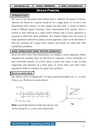
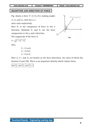
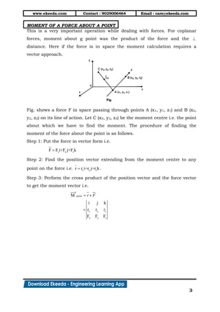
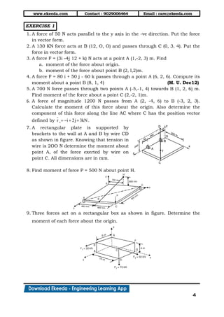

The document introduces the concept of three-dimensional force systems, detailing the vector approach necessary for analyzing such systems. It covers basic operations like representing force vectorially, calculating the resultant of space forces, and examining equilibrium conditions. Additionally, it includes various exercises to reinforce understanding of these principles.


