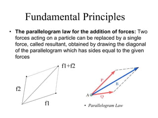
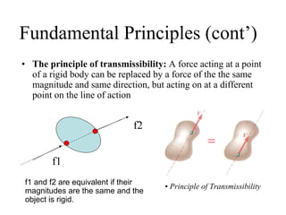
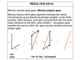
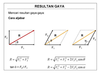
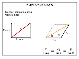
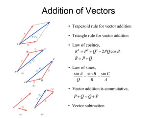
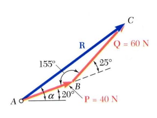
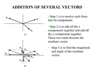
SlideShare a Scribd company logo
MEKANIKA TEKNIK
OLEH:
PRAMONO
JURUSAN TEKNIK MESIN
FT – UNNES
Apa itu Mekanika?
Cabang ilmu fisika yang berbicara tentang
keadaan diam atau geraknya benda-benda
yang mengalami kerja atau aksi gaya
Mechanics
Rigid Bodies
(Things that do not change shape)
Deformable Bodies
(Things that do change shape)
Fluids
Statics Dynamics Incompressible Compressible
Review Sistem Satuan
• Four fundamental physical quantities. Length, Time, Mass, Force.
• We will work with two unit systems in static’s: SI & US Customary.
Bagaimana konversi dari SI ke US atau sebaliknya ?
SISTEM GAYA
SISTEM GAYA
SPACE (3D)
Fundamental Principles
• The parallelogram law for the addition of forces: Two
forces acting on a particle can be replaced by a single
force, called resultant, obtained by drawing the diagonal
of the parallelogram which has sides equal to the given
forces
f1
f2
f1+f2
• Parallelogram Law
Fundamental Principles (cont’)
• The principle of transmissibility: A force acting at a point
of a rigid body can be replaced by a force of the the same
magnitude and same direction, but acting on at a different
point on the line of action
• Principle of Transmissibility
f1
f2
f1 and f2 are equivalent if their
magnitudes are the same and the
object is rigid.
APPLICATION OF VECTOR
ADDITION
There are four
concurrent cable forces
acting on the bracket.
How do you determine
the resultant force acting
on the bracket ?
Addition of Vectors
• Trapezoid rule for vector addition
• Triangle rule for vector addition
B
B
C
C
QPR
BPQQPR
rrr
+=
−+= cos2222
• Law of cosines,
• Law of sines,
A
C
R
B
Q
A sinsinsin
==
• Vector addition is commutative,
PQQP
rrrr
+=+
• Vector subtraction
Sample Problem
The two forces act on a bolt at A.
Determine their resultant.
SOLUTION:
• Trigonometric solution -
use the triangle rule for
vector addition in
conjunction with the law
of cosines and law of
sines to find the resultant.
• Trigonometric solution - Apply the triangle rule.
From the Law of Cosines,
( ) ( ) ( )( ) °−+=
−+=
155cosN60N402N60N40
cos2
22
222
BPQQPR
N73.97=R
From the Law of Sines,
A
A
R
Q
BA
R
B
Q
A
+°=
°=
°=
=
=
20
04.15
N73.97
N60
155sin
sinsin
sinsin
α °= 04.35α
ADDITION OF SEVERAL VECTORS
• Step 3 is to find the magnitude
and angle of the resultant
vector.
• Step 1 is to resolve each force
into its components
• Step 2 is to add all the x
components together and add all
the y components together.
These two totals become the
resultant vector.
Example of this process,
You can also represent a 2-D vector with a
magnitude and angle.
EXAMPLE
Given: Three concurrent forces
acting on a bracket.
Find: The magnitude and
angle of the resultant
force.
Plan:
a) Resolve the forces in their x-y components.
b) Add the respective components to get the resultant vector.
c) Find magnitude and angle from the resultant components.
F1 = { 15 sin 40° i + 15 cos 40° j } kN
= { 9.642 i + 11.49 j } kN
EXAMPLE (continued)
F2 = { -(12/13)26 i + (5/13)26 j } kN
= { -24 i + 10 j } kN
F3 = { 36 cos 30° i – 36 sin 30° j } kN
= { 31.18 i – 18 j } kN
EXAMPLE (continued)
Summing up all the i and j components respectively, we get,
FR = { (9.642 – 24 + 31.18) i + (11.49 + 10 – 18) j } kN
= { 16.82 i + 3.49 j } kN
x
y
φ
FR
FR = ((16.82)2 + (3.49)2)1/2 = 17.2 kN
φ = tan-1(3.49/16.82) = 11.7°
Sample Problem
Four forces act on bolt A as shown.
Determine the resultant of the
force on the bolt.
SOLUTION:
• Resolve each force into
rectangular components.
• Calculate the magnitude and
direction of the resultant.
• Determine the components of the
resultant by adding the
corresponding force components.
Sample Problem (cont’)
SOLUTION:
• Resolve each force into rectangular components.
Sample Problem (cont’)
1.199+=xR 3.14+=yR
9.256.96100
0.1100110
2.754.2780
0.759.129150
4
3
2
1
−+
−
+−
++
−−
F
F
F
F
compycompxmagforce
r
r
r
r
• Determine the components of the resultant by adding the corresponding force
components.
• Calculate the magnitude and direction.
°=== 1.4
N1199
N314
tan αα
.
.
R
R
x
y
°= 1.4α
N6.199
sin
N3.14
==R
MOMEN DAN KOPEL
Apa yang dipelajari sekarang ?
Mengetahui dan memahami maksud dari
momen gaya, momen kopel, dan cara
memindah gaya
Apa itu momen gaya ?
The moment of a force about a point provides a measure of the
tendency for rotation (sometimes called a torque).
MOMENT IN 2-D (continued)
In the 2-D case, the magnitude of the moment is
Mo = F d
As shown, d is the perpendicular distance from point O to the
line of action of the force.
In 2-D, the direction of MO is either clockwise or
counter-clockwise depending on the tendency for rotation.
Moment in 2-D
F
a
b
d
O
ab
O
F
F x
F y
As shown, d is the
perpendicular distance
from point O to the line
Often it is easier to
determine MO by using the
components of F as shown.
of action of the force.
MO = (FY a) – (FX b)
CCW = (+)
CW = (-)
MO = F d
and the direction is
counter-clockwise.
Example 1
Given: A 40 N force is
applied to the wrench.
Find: The moment of the
force at O.
Plan: 1) Resolve the force
along x and y axes.
2) Determine MO using
scalar analysis.
Solution: + ↑ Fy = - 40 cos 20° N
+ → Fx = - 40 sin 20° N
+ MO = {-(40 cos 20°)(200) + (40 sin 20°)(30)}N·mm
= -7107 N·mm = - 7.11 N·m
EXAMPLE 2
Given: A 400 N force is
applied to the frame
and θ = 20°.
Find: The moment of the
force at A.
Plan:
1) Resolve the force along x and y axes.
2) Determine MA using scalar analysis.
EXAMPLE 2 (continued)
Solution
+ ↑ Fy = -400 cos 20° N
+ → Fx = -400 sin 20° N
+ MA = {(400 cos 20°)(2) + (400 sin 20°)(3)} N·m
= 1160 N·m
CONCEPT QUESTION
• A
d = 3 m
F = 10 N
1. What is the moment of the 10 N force
about point A (MA)?
A) 10 N·m B) 30 N·m C) 13 N·m
D) (10/3) N·m E) 7 N·m
2. If a force of magnitude F can be applied in four different 2-D
configurations (P,Q,R, & S), select the cases resulting in the
maximum and minimum torque values on the nut. (Max, Min).
A) (Q, P) B) (R, S)
C) (P, R) D) (Q, S)
R
P Q
S
10 N 5 N
3 m P 2 m
3. Using the CCW direction as positive, the net moment of the
two forces about point P is
A) 10 N ·m B) 20 N ·m C) - 20 N ·m
D) 40 N ·m E) - 40 N ·m
Apa itu momen kopel ?
Moment of a Couple
A couple is defined as two
parallel forces with the same
magnitude but opposite in
direction separated by a
perpendicular distance d.
The moment of a couple is defined as
MO = F d (using a scalar analysis) or as
MO = r × F (using a vector analysis).
Here r is any position vector from the line of action of
–F to the line of action of F.
Problem Solving
A B
A torque or moment of 12 N · m is required to rotate the wheel.
Which one of the two grips of the wheel above will require less
force to rotate the wheel?
Problem Solving (2-D)
A B
M = F d
12 = F 0.3
F = 40 N
M = F d
12 = F 0.4
F = 30 N
PROBLEM SOLVING - SCALAR
Given: Two couples act on the
beam. The resultant couple is
zero.
Find: The magnitudes of the forces
P and F and the distance d.
PLAN:
1) Use definition of a couple to find P and F.
2) Resolve the 300 N force in x and y directions.
3) Determine the net moment.
4) Equate the net moment to zero to find d.
Solution:
From the definition of a
couple
P = 500 N and
F = 300 N.
Resolve the 300 N force into vertical and horizontal
components. The vertical component is (300 cos 30º) N and
the horizontal component is (300 sin 30º) N.
It was given that the net moment equals zero. So
+ ΣM = - (500)(2) + (300 cos 30º)(d) + (300 sin 30º)(0.2) = 0
Now solve this equation for d.
d = (1000 – 60 sin 30º) / (300 cos 30º) = 3.96 m
CONCEPT QUESTION
1. In statics, a couple is defined as __________ separated by a
perpendicular distance.
A) two forces in the same direction.
B) two forces of equal magnitude.
C) two forces of equal magnitude acting in the same direction.
D) two forces of equal magnitude acting in opposite directions.
2. F1 and F2 form a couple. The moment
of the couple is given by ____ .
A) r1 × F1 B) r2 × F1
C) F2 × r1 D) r2 × F2
F1
r1
F2
r2
3. A couple is applied to the beam as shown. Its moment
equals _____ N·m.
A) 50 B) 60
C) 80 D) 100
3
4
51m 2m
50 N
Apa itu memindah gaya ?
Several forces and a
couple moment are
acting on this vertical
section of an I-beam.
Can you replace them
with just one force and
one couple moment at
point O that will have
the same external
effect? If yes, how will
you do that?
AN EQUIVALENT SYSTEM
=
When a number of forces and couple moments are acting on a
body, it is easier to understand their overall effect on the body if
they are combined into a single force and couple moment having
the same external effect
The two force and couple systems are called equivalent systems
since they have the same external effect on the body.
Equivalent Force – Couple Systems
Moving a force from A to O, when both points are on the
vectors’ line of action, does not change the external effect.
Hence, a force vector is called a sliding vector. (But the
internal effect of the force on the body does depend on
where the force is applied).
Equivalent Force – Couple Systems
Moving a force from point A to O (as shown above) requires
creating an additional couple moment. Since this new couple
moment is a “free” vector, it can be applied at any point P on the
body.
Equivalent Force – Couple Systems
If the force system lies in the x-y plane (the 2-D case), then the
reduced equivalent system can be obtained using the following
three scalar equations.
Problem Solving (2-D)
Given: A 2-D force and couple
system as shown.
Find: The equivalent resultant force
and couple moment acting at
A and then the equivalent
single force location along
the beam AB.
Plan:
1) Sum all the x and y components of the forces to find FRA.
2) Find and sum all the moments resulting from moving each
force to A.
3) Shift the FRA to a distance d such that d = MRA/FRy
Problem Solving (2-D)
+ → ΣFRx = 25 + 35 sin 30°
= 42.5 N
+ ↑ ΣFRy = - 20 - 35 cos 30°
= - 50.31 N
+ MRA = - 35 cos30° (0.2)
- 20(0.6) + 25(0.3)
= - 10.56 N.mFR = ( 42.52 + (-50.31)2 )1/2 = 65.9 N
θ = tan-1 ( 50.31/42.5) = 49.8 ° (Kw IV)
FR
d
The equivalent single force FR can be located on the
beam AB at a distance d measured from A.
d = MRA/FRy = - 10.56/(-50.31) = 0.21 m.
KESEIMBANGAN
PARTIKEL (2D)
Equilibrium of a Particle (2-D)
Today’s Objectives:
Students will be able to :
a) Draw a free body diagram
(FBD), and,
b) Apply equations of
equilibrium to solve a 2-D
problem.
For a given cable
strength, what is the
maximum weight
that can be lifted ?
Apa pentingnya mekanika (statik) /
keseimbangan ?
Apa perbedaan partikel dan benda tegar?
• Particle: A very small amount of matter which
may be assumed to occupy a single point in
space.
• Rigid body: A combination of a large number
of particles occupying fixed position with
respect to each other.
Apa perbedaan Partikel dan Benda Tegar ?
Benda Tegar:
Kombinasi sejumlah
partikel yang mana
semua partikel
berada pada suatu
jarak tetap terhadap
satu dengan yang lain
Partikel:
Mempunyai suatu
massa namun
ukurannya dapat
diabaikan, sehingga
geometri benda tidak
akan terlibat dalam
analisis masalah
Contoh Partikel
Contoh Benda Tegar
THE WHAT, WHY AND HOW OF A
FREE BODY DIAGRAM (FBD)
Free Body Diagrams are one of the most important things for
you to know how to draw and use.
What ? - It is a drawing that shows
all external forces acting on the
particle.
Why ? - It helps you write the
equations of equilibrium used to
solve for the unknowns (usually
forces or angles).
How ?
1. Imagine the particle to be isolated or cut free from its
surroundings.
2. Show all the forces that act on the particle.
Active forces: They want to move the particle.
Reactive forces: They tend to resist the motion.
3. Identify each force and show all known magnitudes
and directions. Show all unknown magnitudes and /
or directions as variables .
Note : Engine mass = 250 Kg
A
FBD at A
Free Body Diagram (FBD) (2-D)
Equations of Equilibrium (2-D)
Since particle A is in equilibrium,
the net force at A is zero.
So FAB + FAD + FAC = 0
or Σ F = 0
In general, for a particle in equilibrium, Σ F = 0 or
ΣFx i + ΣFy j = 0 = 0 i + 0 j (A vector equation)
Or, written in a scalar form,
These are two scalar equations of equilibrium (EofE). They
can be used to solve for up to two unknowns.
ΣFx = 0 and Σ Fy = 0
EXAMPLE
Note : Engine mass = 250 Kg FBD at A
Write the scalar EofE:
+ → Σ Fx = TB cos 30º – TD = 0
+ ↑ ΣFy = TB sin 30º – 2.452 kN = 0
Solving the second equation gives: TB = 4.90 kN
From the first equation, we get: TD = 4.25 kN
Problem Solving (2-D)
F = 600 N
θ = 25o
Given: The car is towed at constant
speed by the 600 N force
and the angle θ is 25°.
Find: The forces in the ropes AB
and AC.
Plan:
1. Draw a FBD for point A.
2. Apply the EofE to solve for the forces
in ropes AB and AC.
Problem Solving (2-D)
F = 600 N
θ = 25o
30°25°
600 N
FAB
FAC
A
FBD at point A
Applying the scalar EofE at A, we get;
+ → ∑Fx = FAC cos 30° – FAB cos 25° = 0
+ → ∑Fy = -FAC sin 30° – FAB sin 25° + 600 = 0
Solving the above equations, we get;
FAB = 634 N
FAC = 664 N
Example
SOLUTION:
• Construct a free-body diagram for the
particle at the junction of the rope and
cable.
• Determine the unknown force
magnitudes.
In a ship-unloading operation, a
15.6 kN automobile is supported by
a cable. A rope is tied to the cable
and pulled to center the automobile
over its intended position. What is
the tension in the rope?
EXAMPLE
Given: Sack A weighs 20 N.
and geometry is as
shown.
Find: Forces in the cables and
weight of sack B.
Plan:
1. Draw a FBD for Point E.
2. Apply EofE at Point E to solve
for the unknowns (TEG & TEC).
3. Repeat this process at C.
EXAMPLE (continued)
A FBD at E should look like the one
to the left. Note the assumed
directions for the two cable tensions.
The scalar EofE are:
+ → Σ Fx = TEG sin 30º – TEC cos 45º = 0
+ ↑ Σ Fy = TEG cos 30º – TEC sin 45º – 20 N = 0
Solving these two simultaneous equations for the
two unknowns yields:
TEC = 38.6 N
TEG = 54.6 N
EXAMPLE (continued)
Now move on to ring C.
A FBD for C should look
like the one to the left.
The scalar EofE are:
+ → Σ Fx = 38.64 cos 45° – (4/5) TCD = 0
+ ↑ Σ Fy = (3/5) TCD + 38.64 sin 45° – WB = 0
Solving the first equation and then the second yields
TCD = 34.2 N and WB = 47.8 N .
READING QUIZ
1) When a particle is in equilibrium, the sum of forces acting
on it equals ___ . (Choose the most appropriate answer)
A) a constant B) a positive number C) zero
D) a negative number E) an integer.
2) For a frictionless pulley and cable, tensions in the cable
(T1 and T2) are related as _____ .
A) T1 > T2
B) T1 = T2
C) T1 < T2
D) T1 = T2 sin θ
ATTENTION QUIZ
3. Using this FBD of Point C, the sum of
forces in the x-direction (Σ FX) is ___ .
Use a sign convention of + → .
A) F2 sin 50° – 20 = 0
B) F2 cos 50° – 20 = 0
C) F2 sin 50° – F1 = 0
D) F2 cos 50° + 20 = 0
F2
20 N
F1
C
50°
SOAL TANTANGAN
40 kg
80 kg
5 m
10 m
a
b
A
B
C
P
Jika b = 4 m,
tentukan harga P dan jarak a
KESEIMBANGAN
BENDA TEGAR
Apa Beda Partikel dengan Benda Tegar ?
Forces on a particle
In contrast to the forces on a particle, the
forces on a rigid-body are not usually
concurrent and may cause rotation of the
body (due to the moments created by the
forces).
Forces on a rigid body
For a rigid body to be in equilibrium, the
net force as well as the net moment
about any arbitrary point O must be
equal to zero.
∑ F = 0 and ∑ MO = 0
Benda Tegar Biasanya Memiliki Tumpuan
Macam-macam Tumpuan dan Reaksinya
Contoh Menggambar FBD nya
Free body diagramIdealized model
Lho kok ada beban yang segiempat, apa itu?
Beban Terdistribusi
Mencari Gaya Resultan pada Beban Terdistribusi
• Mencari titik berat dari beban terdistribusi
• Gaya resultan sama dengan luasan dari beban
terdistribusi
• Gaya resultan terletak pada titik berat beban
terdisribusi
Kalo beban terdistribusinya berbentuk segitiga ?
2. x = __________.
A) 3 m B) 4 m
C) 6 m D) 8 m
1. FR = ____________
A) 12 N B) 100 N
C) 600 N D) 1200 N
FR100 N/m
12 m x
Prosedur Menyelesaikan Soal
• Gambar FBD dari soal
• Jangan lupa kasih perjanjian tandanya
• Gambar gaya reaksi yang ada
• Kalo ada beban terdistribusi, cari dulu besar
gaya resultan, dan posisinya
• Hitung besar gaya reaksi di tumpuan,
menggunakan
∑ Fx = 0 ∑ Fy = 0 ∑ Mo = 0
titik O itu titik apa? Yang mana?
Contoh Soal 1
Given: Weight of the boom =
125 lb, the center of
mass is at G, and the
load = 600 lb.
Find: Support reactions at A
and B.
Plan:
1. Put the x and y axes in the horizontal and vertical directions,
respectively.
2. Draw a complete FBD of the boom.
3. Apply the EofE to solve for the unknowns.
Contoh Soal 1 (Jawaban)
AX
AY
A
1 ft 1 ft 3 ft 5 ft
B G
D
600 lb125 lbFB
40°
FBD of the boom:
+ ∑MA = - 125 ∗ 4 - 600 ∗ 9 + FB sin 40° ∗ 1 + FB cos 40° ∗ 1 = 0
FB = 4188 lb or 4190 lb
→ + ∑FX = AX + 4188 cos 40° = 0; AX = – 3210 lb
↑ + ∑FY = AY + 4188 sin 40° – 125 – 600 = 0; AY = – 1970 lb
Contoh Soal 2
A fixed crane has a mass of 1000 kg
and is used to lift a 2400 kg crate. It
is held in place by a pin at A and a
rocker at B. The center of gravity of
the crane is located at G.
Determine the components of the
reactions at A and B.
SOLUTION:
• Create a free-body diagram for the crane.
• Determine B by solving the equation for
the sum of the moments of all forces
about A. Note there will be no
contribution from the unknown
reactions at A.
• Determine the reactions at A by
solving the equations for the sum of
all horizontal force components and
all vertical force components.
• Check the values obtained for the
reactions by verifying that the sum of
the moments about B of all forces is
zero.
Contoh Soal 2 (jawaban)
• Determine B by solving the equation for the
sum of the moments of all forces about A.
( ) ( )
( ) 0m6kN5.23
m2kN81.9m5.1:0
=−
−∑ += BM A
kN1.107+=B
• Determine the reactions at A by solving the
equations for the sum of all horizontal forces
and all vertical forces.
0:0 =+=∑ BAF xx
kN1.107−=xA
• Create the free-body diagram.
0kN5.23kN81.9:0 =−−=∑ yy AF
kN3.33+=yA
• Check the values obtained.
Contoh Soal 3
↓=
−=
−+−==Σ
↑=
−
−−
=
−−==Σ
N18.75
75.18
22575.3631200
N363.75
400.
)500(.225)275(.120
)500(.225)275(.120)(400.0
y
y
y
y
yA
A
NA
NNNAyFy
B
m
mNmN
B
mNmNBmM
+
+
Contoh Soal 4
Given: The loading on the beam as
shown.
Find: Support reactions at A and B.
Contoh Soal 4 (jawaban)
SOLUTION:
• Taking entire beam as a free-body,
determine reactions at supports. :0∑ =yF
0kN54kN117kN54kN90 =−+−−yA
kN81=yA
∑ = :0AM
( ) ( )( ) ( )( )
( )( ) 0m.48kN45
m.24kN45m.81kN90m.27
=−
−−D
kN117=D
Contoh Soal 5
Tentukan Reaksi di A dan B
Soal Tantangan
Given: The loading on the beam as shown.
Find: Reaction at B and A
Soal Tantangan (2)
Tentukan Reaksi di A dan C
BEAM
GAYA INTERNAL,
DIAGRAM GAYA GESER
DAN MOMEN
Definisi Beam
• Beam - structural member designed to support
loads applied at various points along its length.
• Beam can be subjected to concentrated loads or
distributed loads or combination of both.
• Beam design is two-step process:
1) determine shearing forces and bending
moments produced by applied loads
2) select cross-section best suited to resist
shearing forces and bending moments
Apa itu Gaya Internal ?
Gaya Internal : gaya yang mengikat bersama berbagai
bagian struktur sehingga struktur tersebut menjadi kokoh
• Straight two-force member AB is in
equilibrium under application of F and
-F.
• Internal forces equivalent to F and -F are
required for equilibrium of free-bodies AC
and CB.
Reaksi pada Beam
• Beams are classified according to way in which they are
supported.
• Reactions at beam supports are determinate if they
involve only three unknowns. Otherwise, they are
statically indeterminate.
Gaya Geser dan Momen pada Beam
• Wish to determine bending moment
and shearing force at any point in a
beam subjected to concentrated and
distributed loads.
• Determine reactions at supports by
treating whole beam as free-body.
• Cut beam at C and draw free-body
diagrams for AC and CB. By
definition, positive sense for internal
force-couple systems are as shown.
• From equilibrium considerations,
determine M and V or M’ and V’.
Diagram Gaya Geser dan Momen pada Beam
• Variation of shear and bending
moment along beam may be
plotted.
• Determine reactions at
supports.
• Cut beam at C and consider
member AC,
22 PxMPV +=+=
• Cut beam at E and consider
member EB,
( ) 22 xLPMPV −+=−=
• For a beam subjected to
concentrated loads, shear is
constant between loading points
and moment varies linearly.
Contoh Soal 1
Draw the shear and bending moment
diagrams for the beam and loading
shown.
SOLUTION:
• Taking entire beam as a free-body,
calculate reactions at B and D.
• Find equivalent internal force-couple
systems for free-bodies formed by
cutting beam on either side of load
application points.
• Plot results.
Contoh Soal 1 (jawaban)
• Plot results.
Note that shear is of constant value
between concentrated loads and
bending moment varies linearly.
Contoh Soal 2
Given: A beam is supported
by a hinge at A, a roller at
B. Force applied at C.
Moment applied at D.
Find: Draw the shear and
bending moment diagrams
Plan:
a) Draw a FBD of the beam.
b)Calculate support reactions.
c) Find equivalent internal force-couple systems for free-bodies formed
by cutting beam on either side of load application points.
Contoh Soal 2 (jawaban)
Ay By
ΣFy = 0
Ay + By – 600 = 0
0.1 + By – 0.6 = 0
By = 0.5 kip
ΣMB = 0
- Ay(20) + 0.6(10) – 4 = 0
20Ay = 6 - 4
Ay = 0.1 kip
Contoh Soal 2 (jawaban)
Potongan 1-1
0.1 kip 0.5 kip
1
1
2
2
3
3
0.1 kip
0 ≤ x < 10 ft
V
M
x
ΣF1-1 = 0
0.1 – V = 0
V = 0.1 kip
x = 0 ft VA = 0.1 kip
x = 10 ft VC = 0.1 kip
ΣM1-1 = 0
M – 0.1(x) = 0
M = 0.1(x)
x = 0 ft MA = 0.1(0) = 0 kip-ft
x = 10 ft MC = 0.1(10) = 1 kip-ft
Contoh Soal 2 (jawaban)
Potongan 2-2
ΣF2-2 = 0
0.1 – 0.6 – V = 0
V = 0.1 – 0.6 kip
V = - 0.5 kip
x = 10 ft VC = - 0.5 kip
x = 15 ft VD = - 0.5 kip
ΣM2-2 = 0
M – 0.1(x) + 0.6(x – 10) = 0
M – 0.1(x) + 0.6(x) – 6 = 0
M = - 0.5(x) + 6
x = 10 ft MC = - 0.5(10) + 6 = 1 kip-ft
x = 15 ft MD = - 0.5(15) + 6 = - 1.5 kip-ft
0.1 kip
10 ≤ x < 15 ft
V
M
x
0.1 kip 0.5 kip
1
1
2
2
3
3
Contoh Soal 2 (jawaban)
Potongan 3-3
0.1 kip 0.5 kip
1
1
2
2
3
3
0.1 kip
15 ≤ x < 20 ft
V
M
x
ΣF3-3 = 0
0.1 – 0.6 – V = 0
V = 0.1 – 0.6 kip
V = - 0.5 kip
x = 15 ft VD = - 0.5 kip
x = 20 ft VD = - 0.5 kip
ΣM3-3 = 0
M – 0.1(x) + 0.6(x – 10) – 4 = 0
M – 0.1(x) + 0.6(x) – 6 – 4 = 0
M = - 0.5(x) + 10
x = 15 ft MD = - 0.5(15) + 10 = 2.5 kip-ft
x = 20 ft MB = - 0.5(20) + 10 = 0 kip-ft
Contoh Soal 2 (jawaban)
Diagram Geser dan Momen
ΣM1-1 = 0
M = 0.1(x)
MA= 0 kip-ft
MC= 1 kip-ft
ΣM2-2 = 0
M = - 0.5(x) + 6
MC= 1 kip-ft
MD= - 1.5 kip-ft
ΣM3-3 = 0
M = - 0.5(x) + 10
MD= 2.5 kip-ft
MB= 0 kip-ft
ΣF1-1 = 0
V = 0.1 kip
VA = 0.1 kip
VC = 0.1 kip
ΣF2-2 = 0
V = - 0.5 kip
VC = - 0.5 kip
VD = - 0.5 kip
ΣF3-3 = 0
V = - 0.5 kip
VD = - 0.5 kip
VB = - 0.5 kip
Contoh Soal 3
Draw the shear and bending moment
diagrams for the beam AB. The
distributed load of 7200 N/m. extends
over 0.3 m of the beam, from A to C,
and the 1800 N load is applied at E.
SOLUTION:
• Taking entire beam as free-body,
calculate reactions at A and B.
• Determine equivalent internal force-
couple systems at sections cut within
segments AC, CD, and DB.
• Plot results.
Contoh Soal 3 (jawaban)
SOLUTION:
• Taking entire beam as a free-body, calculate
reactions at A and B.
:0=∑ AM
( ) ( )( ) ( )( ) 0m55.0N1800m15.0N2160m8.0 =−−yB
N1642=yB
:0=∑ BM
( )( ) ( )( ) ( ) 0m8.0m25.0N1800m65.0N2160 =−+ A
N2318=A
:0=∑ xF 0=xB
• Note: The 1800 N load at E may be replaced by
a 1800 N force and 180 Nm. couple at D.
Contoh Soal 3 (jawaban)
:01 =∑M ( ) 072002318 2
1
=++− Mxxx
2
36002318 xxM −=
:02 =∑M ( ) 015.021602318 =+−+− Mxx
( ) mN158324 ⋅+= xM
From C to D:
∑ = :0yF 021602318 =−− V
N158=V
• Evaluate equivalent internal force-couple systems
at sections cut within segments AC, CD, and DB.
From A to C:
∑ = :0yF 072002318 =−− Vx
xV 72002318−=
Contoh Soal 3 (jawaban)
:02 =∑M
( ) ( ) 045.0180018015.021602318 =+−+−−+− Mxxx
( ) mN16421314 ⋅−= xM
• Evaluate equivalent internal force-couple
systems at sections cut within segments AC,
CD, and DB.
From D to B:
∑ = :0yF 0180021602318 =−−− V
N1642−=V
Contoh Soal 3 (jawaban)
• Plot results.
From A to C:
xV 72003218 −=
2
203218 xxM −=
From C to D:
N158=V
( ) mN158324 ⋅+= xM
From D to B:
N1642−=V
( ) mN16421314 ⋅−= xM
Contoh Soal 4
Draw the shear and bending-moment diagrams
for the beam and loading shown.
Contoh Soal 4 (jawaban)
What’s Stopping You?
Fn
Mu
Friction
Hard to Live With It, Can’t Live Without It
Coefficient of Friction
Consider 2 Types of Friction
sF
Force of Kinetic Friction
This value represents the relative force necessary
to keep an object moving at a constant rate
kF
Force of Static Friction
This value represents the relative force necessary
to make an object move
FrictionalForce
ResistingMotion
Force Causing the Object to Move
Kinetic RegionStatic Region
sF
kFkFF ≥s
kFF ≥s
Max
Frictional Forces Occur When
Materials are in Contact
W
fs
F
N
Surfaces in
Contact
M1
Spring Scale
F = Force Causing Motion (Pull on Scale)
Fs = Force of Static Friction (Resists Motion)
N = Force Normal Holds Surfaces in Contact
W = Weight of Object ( Mass x Gravity)
Friction is a Force That
Resists Motion
W
fs
F
N
Surfaces in
Contact
M1
Spring Scale
The Pink Block M1 Will not Move Until the
Force F (Pull on the scale ) Exceeds the
Force of Static Friction fs.
The Relative Force of Static Friction Between
2 Objects is Expressed as the Quotient of
the Force (F) Required to Move the
Object
W
fs
F
N
Surfaces in
Contact
M1
Spring Scale
Divided by the Weight W of the Object
This is Called the Coefficient of
Friction
W
fs
F
N
Surfaces in
Contact
M1
W
F
s =µ
Coefficient of Static
Friction
µ
Spring Scale
sµ
F
= Coefficient of Friction
= Force Required to Cause Motion
= Weight of ObjectW
Using the Gears-IDS Battery to
Calculate The Staticsµ
W
F
s =µ
Coefficient of Friction
Record the Maximum Force (F)
(Before the Battery Begins to Move)
W
F
s =µ
Maximum Force F = 110 g
Record the Weight
(W ) of the Battery
W
F
s =µ
580 g
The Coefficient of Static Friction Between
the Wood Desktop and the Plastic Battery
is Described Algebraically:
W
F
s =µ = 110 g
= 580 g
sµ = .190
The Coefficient of Kinetic Friction Can
be Found Using the Same Technique
W
F
k =µ
Record the Force Required to Move
the Battery at a Constant Rate
Coefficients of Friction Between Various
Surfaces Have Significant Impact on the
Design and Construction of Mechanisms.
The Design of Competitive
Mechanisms with Wheels Requires
Extensive Testing in Order to
Optimize the Torque, Speed and
Traction (Friction) of the Drive
Systems.
The End

More Related Content

What's hot

METODE GARIS PENGARUH STRUKTUR RANGKA BATANG(1)
METODE GARIS PENGARUH STRUKTUR RANGKA BATANG(1)METODE GARIS PENGARUH STRUKTUR RANGKA BATANG(1)
METODE GARIS PENGARUH STRUKTUR RANGKA BATANG(1)
MOSES HADUN
 
Kalkulus 2 bab. Aplikasi Integral Rangkap Dua (Menghitung Pusat Massa)
Kalkulus 2 bab. Aplikasi Integral Rangkap Dua (Menghitung Pusat Massa)Kalkulus 2 bab. Aplikasi Integral Rangkap Dua (Menghitung Pusat Massa)
Kalkulus 2 bab. Aplikasi Integral Rangkap Dua (Menghitung Pusat Massa)Neria Yovita
 
Bab 07 poros dan aksesoriny
Bab 07 poros dan aksesorinyBab 07 poros dan aksesoriny
Bab 07 poros dan aksesoriny
Rumah Belajar
 
Mekanika Kekuatan Material 1
Mekanika Kekuatan Material 1Mekanika Kekuatan Material 1
Mekanika Kekuatan Material 1frendi prasetyo
 
Bab ii distribusi momen
Bab ii distribusi momenBab ii distribusi momen
Bab ii distribusi momen
dika andika
 
Matematika kelas xi turunan fungsi
Matematika kelas xi turunan fungsiMatematika kelas xi turunan fungsi
Matematika kelas xi turunan fungsiSiti Lestari
 
Materi vektor dalam aplikasi teknik sipil
Materi vektor dalam aplikasi teknik sipilMateri vektor dalam aplikasi teknik sipil
Materi vektor dalam aplikasi teknik sipil
Rizky Islami
 
04 momen inersia
04   momen inersia04   momen inersia
04 momen inersia
tekpal14
 
Geometri ddimensi 3
Geometri ddimensi 3Geometri ddimensi 3
Geometri ddimensi 3Zafit Nurdin
 
Materi Struktur Baja I Pertemuan ke-2
Materi Struktur Baja I Pertemuan ke-2Materi Struktur Baja I Pertemuan ke-2
Materi Struktur Baja I Pertemuan ke-2
Lampung University
 
Chapter 07 in som
Chapter 07 in som Chapter 07 in som
Chapter 07 in som
University Malaysia Pahang
 
4 portal-dan-pelengkung-tiga-sendi
4 portal-dan-pelengkung-tiga-sendi4 portal-dan-pelengkung-tiga-sendi
4 portal-dan-pelengkung-tiga-sendi
IgorTherik
 
Modul 1-pengertian-dasar-statika, STATIKA DAN MEKANIKA DASAR
Modul 1-pengertian-dasar-statika, STATIKA DAN MEKANIKA DASARModul 1-pengertian-dasar-statika, STATIKA DAN MEKANIKA DASAR
Modul 1-pengertian-dasar-statika, STATIKA DAN MEKANIKA DASAR
MOSES HADUN
 
Perc. 7 pusat gravitasi dan pusat massa
Perc. 7 pusat gravitasi dan pusat massaPerc. 7 pusat gravitasi dan pusat massa
Perc. 7 pusat gravitasi dan pusat massa
SMA Negeri 9 KERINCI
 
Kuliah dinamika-lengkap
Kuliah dinamika-lengkapKuliah dinamika-lengkap
Kuliah dinamika-lengkap
Wildan Noer Fargiant
 

What's hot (20)

METODE GARIS PENGARUH STRUKTUR RANGKA BATANG(1)
METODE GARIS PENGARUH STRUKTUR RANGKA BATANG(1)METODE GARIS PENGARUH STRUKTUR RANGKA BATANG(1)
METODE GARIS PENGARUH STRUKTUR RANGKA BATANG(1)
 
Kalkulus 2 bab. Aplikasi Integral Rangkap Dua (Menghitung Pusat Massa)
Kalkulus 2 bab. Aplikasi Integral Rangkap Dua (Menghitung Pusat Massa)Kalkulus 2 bab. Aplikasi Integral Rangkap Dua (Menghitung Pusat Massa)
Kalkulus 2 bab. Aplikasi Integral Rangkap Dua (Menghitung Pusat Massa)
 
Rumus hardness test
Rumus hardness testRumus hardness test
Rumus hardness test
 
Bab 07 poros dan aksesoriny
Bab 07 poros dan aksesorinyBab 07 poros dan aksesoriny
Bab 07 poros dan aksesoriny
 
Met 1 2
Met 1 2Met 1 2
Met 1 2
 
Mekanika Kekuatan Material 1
Mekanika Kekuatan Material 1Mekanika Kekuatan Material 1
Mekanika Kekuatan Material 1
 
Bab ii distribusi momen
Bab ii distribusi momenBab ii distribusi momen
Bab ii distribusi momen
 
Tegangan
TeganganTegangan
Tegangan
 
Matematika kelas xi turunan fungsi
Matematika kelas xi turunan fungsiMatematika kelas xi turunan fungsi
Matematika kelas xi turunan fungsi
 
Lingkaran Mohr utk tegangan
Lingkaran Mohr utk teganganLingkaran Mohr utk tegangan
Lingkaran Mohr utk tegangan
 
Materi vektor dalam aplikasi teknik sipil
Materi vektor dalam aplikasi teknik sipilMateri vektor dalam aplikasi teknik sipil
Materi vektor dalam aplikasi teknik sipil
 
04 momen inersia
04   momen inersia04   momen inersia
04 momen inersia
 
Geometri ddimensi 3
Geometri ddimensi 3Geometri ddimensi 3
Geometri ddimensi 3
 
Materi Struktur Baja I Pertemuan ke-2
Materi Struktur Baja I Pertemuan ke-2Materi Struktur Baja I Pertemuan ke-2
Materi Struktur Baja I Pertemuan ke-2
 
Chapter 07 in som
Chapter 07 in som Chapter 07 in som
Chapter 07 in som
 
4 portal-dan-pelengkung-tiga-sendi
4 portal-dan-pelengkung-tiga-sendi4 portal-dan-pelengkung-tiga-sendi
4 portal-dan-pelengkung-tiga-sendi
 
Mekanika teknik
Mekanika teknikMekanika teknik
Mekanika teknik
 
Modul 1-pengertian-dasar-statika, STATIKA DAN MEKANIKA DASAR
Modul 1-pengertian-dasar-statika, STATIKA DAN MEKANIKA DASARModul 1-pengertian-dasar-statika, STATIKA DAN MEKANIKA DASAR
Modul 1-pengertian-dasar-statika, STATIKA DAN MEKANIKA DASAR
 
Perc. 7 pusat gravitasi dan pusat massa
Perc. 7 pusat gravitasi dan pusat massaPerc. 7 pusat gravitasi dan pusat massa
Perc. 7 pusat gravitasi dan pusat massa
 
Kuliah dinamika-lengkap
Kuliah dinamika-lengkapKuliah dinamika-lengkap
Kuliah dinamika-lengkap
 

Similar to Mekanikateknik 140330175907-phpapp01

16201806 bahan-ajar-ptm117-mekanika-teknik
16201806 bahan-ajar-ptm117-mekanika-teknik16201806 bahan-ajar-ptm117-mekanika-teknik
16201806 bahan-ajar-ptm117-mekanika-teknikDedy Wonkso
 
chap2_force_systems - Copy.ppt
chap2_force_systems - Copy.pptchap2_force_systems - Copy.ppt
chap2_force_systems - Copy.ppt
teseraaddis1
 
Unit 2 mm9400 ver 1.1(2014)
Unit 2 mm9400 ver 1.1(2014)Unit 2 mm9400 ver 1.1(2014)
Unit 2 mm9400 ver 1.1(2014)
all_engineering
 
ME 245_ 2.pptx
ME 245_ 2.pptxME 245_ 2.pptx
ME 245_ 2.pptx
LendryNorman
 
2-vector operation and force analysis.ppt
2-vector operation and force analysis.ppt2-vector operation and force analysis.ppt
2-vector operation and force analysis.ppt
RanaUmair74
 
Ch 3_rajib1.pptx
Ch 3_rajib1.pptxCh 3_rajib1.pptx
Ch 3_rajib1.pptx
Rajib Barua
 
Equilibrium
EquilibriumEquilibrium
Equilibrium
wallflower018
 
241 wikarta-kuliah-iii-momen-gaya
241 wikarta-kuliah-iii-momen-gaya241 wikarta-kuliah-iii-momen-gaya
241 wikarta-kuliah-iii-momen-gaya
EndraBackbrown
 
Ch06 ssm
Ch06 ssmCh06 ssm
Ch06 ssm
Marta Díaz
 
Shear Force Diagram and its exampls
Shear Force Diagram and its examplsShear Force Diagram and its exampls
Shear Force Diagram and its exampls
Jaydrath Sindhav
 
chapter1and2.ppt
chapter1and2.pptchapter1and2.ppt
chapter1and2.ppt
RanaUmair74
 
Mun unit5 cdp_slide_share
Mun unit5 cdp_slide_shareMun unit5 cdp_slide_share
Mun unit5 cdp_slide_shareJi Hyon Mun
 
Lecture Notes For Section 4.5
Lecture  Notes For  Section 4.5Lecture  Notes For  Section 4.5
Lecture Notes For Section 4.5
Daniel Fernandez
 
Unit 1. force system, solved problems on force system.pdf
Unit 1. force system, solved problems on force system.pdfUnit 1. force system, solved problems on force system.pdf
Unit 1. force system, solved problems on force system.pdf
Vrushali Nalawade
 
Concurrent Force System SPP.pptx
Concurrent Force System SPP.pptxConcurrent Force System SPP.pptx
Concurrent Force System SPP.pptx
Samirsinh Parmar
 
Resultant of forces
Resultant of forcesResultant of forces
Resultant of forces
HUSSAIN SHAIK
 

Similar to Mekanikateknik 140330175907-phpapp01 (20)

16201806 bahan-ajar-ptm117-mekanika-teknik
16201806 bahan-ajar-ptm117-mekanika-teknik16201806 bahan-ajar-ptm117-mekanika-teknik
16201806 bahan-ajar-ptm117-mekanika-teknik
 
chap2_force_systems - Copy.ppt
chap2_force_systems - Copy.pptchap2_force_systems - Copy.ppt
chap2_force_systems - Copy.ppt
 
Unit 2 mm9400 ver 1.1(2014)
Unit 2 mm9400 ver 1.1(2014)Unit 2 mm9400 ver 1.1(2014)
Unit 2 mm9400 ver 1.1(2014)
 
ME 245_ 2.pptx
ME 245_ 2.pptxME 245_ 2.pptx
ME 245_ 2.pptx
 
2-vector operation and force analysis.ppt
2-vector operation and force analysis.ppt2-vector operation and force analysis.ppt
2-vector operation and force analysis.ppt
 
Ch 3_rajib1.pptx
Ch 3_rajib1.pptxCh 3_rajib1.pptx
Ch 3_rajib1.pptx
 
Capitulo2
Capitulo2Capitulo2
Capitulo2
 
Equilibrium
EquilibriumEquilibrium
Equilibrium
 
Gr
GrGr
Gr
 
241 wikarta-kuliah-iii-momen-gaya
241 wikarta-kuliah-iii-momen-gaya241 wikarta-kuliah-iii-momen-gaya
241 wikarta-kuliah-iii-momen-gaya
 
Ch06 ssm
Ch06 ssmCh06 ssm
Ch06 ssm
 
Shear Force Diagram and its exampls
Shear Force Diagram and its examplsShear Force Diagram and its exampls
Shear Force Diagram and its exampls
 
chapter1and2.ppt
chapter1and2.pptchapter1and2.ppt
chapter1and2.ppt
 
Assignment no 1
Assignment no 1Assignment no 1
Assignment no 1
 
Ks
KsKs
Ks
 
Mun unit5 cdp_slide_share
Mun unit5 cdp_slide_shareMun unit5 cdp_slide_share
Mun unit5 cdp_slide_share
 
Lecture Notes For Section 4.5
Lecture  Notes For  Section 4.5Lecture  Notes For  Section 4.5
Lecture Notes For Section 4.5
 
Unit 1. force system, solved problems on force system.pdf
Unit 1. force system, solved problems on force system.pdfUnit 1. force system, solved problems on force system.pdf
Unit 1. force system, solved problems on force system.pdf
 
Concurrent Force System SPP.pptx
Concurrent Force System SPP.pptxConcurrent Force System SPP.pptx
Concurrent Force System SPP.pptx
 
Resultant of forces
Resultant of forcesResultant of forces
Resultant of forces
 

More from frans2014

Tugassejaraharsitektur 131112083046-phpapp01
Tugassejaraharsitektur 131112083046-phpapp01Tugassejaraharsitektur 131112083046-phpapp01
Tugassejaraharsitektur 131112083046-phpapp01
frans2014
 
Analisa ecotects
Analisa ecotectsAnalisa ecotects
Analisa ecotectsfrans2014
 
Sun saver controller
Sun saver controllerSun saver controller
Sun saver controllerfrans2014
 
Sun guard controller
Sun guard controllerSun guard controller
Sun guard controllerfrans2014
 
S1 teoper-2-konsepdasarperencanaanpembangunan-130614084228-phpapp02
S1 teoper-2-konsepdasarperencanaanpembangunan-130614084228-phpapp02S1 teoper-2-konsepdasarperencanaanpembangunan-130614084228-phpapp02
S1 teoper-2-konsepdasarperencanaanpembangunan-130614084228-phpapp02frans2014
 
Arsitekturtropissem4 120528120320-phpapp02
Arsitekturtropissem4 120528120320-phpapp02Arsitekturtropissem4 120528120320-phpapp02
Arsitekturtropissem4 120528120320-phpapp02frans2014
 
Perencanaan sambungan-profil-baja
Perencanaan sambungan-profil-bajaPerencanaan sambungan-profil-baja
Perencanaan sambungan-profil-bajafrans2014
 
A 130713072008-phpapp01
A 130713072008-phpapp01A 130713072008-phpapp01
A 130713072008-phpapp01frans2014
 
Mekanika tanah
Mekanika tanahMekanika tanah
Mekanika tanahfrans2014
 
Mekanika teknik2
Mekanika teknik2Mekanika teknik2
Mekanika teknik2frans2014
 
Modul 9-sesi-1-pelengkung-tiga-sendi-140329054411-phpapp02
Modul 9-sesi-1-pelengkung-tiga-sendi-140329054411-phpapp02Modul 9-sesi-1-pelengkung-tiga-sendi-140329054411-phpapp02
Modul 9-sesi-1-pelengkung-tiga-sendi-140329054411-phpapp02frans2014
 
Modulmekanikateknik1 121101215953-phpapp01
Modulmekanikateknik1 121101215953-phpapp01Modulmekanikateknik1 121101215953-phpapp01
Modulmekanikateknik1 121101215953-phpapp01frans2014
 
Pp65tahun2005
Pp65tahun2005Pp65tahun2005
Pp65tahun2005frans2014
 
Gambar proyeksi
Gambar proyeksiGambar proyeksi
Gambar proyeksifrans2014
 
Teknik distribusi tenaga listrik
Teknik distribusi tenaga listrikTeknik distribusi tenaga listrik
Teknik distribusi tenaga listrikfrans2014
 
Ppipp copy-130823044640-phpapp02
Ppipp copy-130823044640-phpapp02Ppipp copy-130823044640-phpapp02
Ppipp copy-130823044640-phpapp02frans2014
 
130 229-1-pb
130 229-1-pb130 229-1-pb
130 229-1-pbfrans2014
 

More from frans2014 (17)

Tugassejaraharsitektur 131112083046-phpapp01
Tugassejaraharsitektur 131112083046-phpapp01Tugassejaraharsitektur 131112083046-phpapp01
Tugassejaraharsitektur 131112083046-phpapp01
 
Analisa ecotects
Analisa ecotectsAnalisa ecotects
Analisa ecotects
 
Sun saver controller
Sun saver controllerSun saver controller
Sun saver controller
 
Sun guard controller
Sun guard controllerSun guard controller
Sun guard controller
 
S1 teoper-2-konsepdasarperencanaanpembangunan-130614084228-phpapp02
S1 teoper-2-konsepdasarperencanaanpembangunan-130614084228-phpapp02S1 teoper-2-konsepdasarperencanaanpembangunan-130614084228-phpapp02
S1 teoper-2-konsepdasarperencanaanpembangunan-130614084228-phpapp02
 
Arsitekturtropissem4 120528120320-phpapp02
Arsitekturtropissem4 120528120320-phpapp02Arsitekturtropissem4 120528120320-phpapp02
Arsitekturtropissem4 120528120320-phpapp02
 
Perencanaan sambungan-profil-baja
Perencanaan sambungan-profil-bajaPerencanaan sambungan-profil-baja
Perencanaan sambungan-profil-baja
 
A 130713072008-phpapp01
A 130713072008-phpapp01A 130713072008-phpapp01
A 130713072008-phpapp01
 
Mekanika tanah
Mekanika tanahMekanika tanah
Mekanika tanah
 
Mekanika teknik2
Mekanika teknik2Mekanika teknik2
Mekanika teknik2
 
Modul 9-sesi-1-pelengkung-tiga-sendi-140329054411-phpapp02
Modul 9-sesi-1-pelengkung-tiga-sendi-140329054411-phpapp02Modul 9-sesi-1-pelengkung-tiga-sendi-140329054411-phpapp02
Modul 9-sesi-1-pelengkung-tiga-sendi-140329054411-phpapp02
 
Modulmekanikateknik1 121101215953-phpapp01
Modulmekanikateknik1 121101215953-phpapp01Modulmekanikateknik1 121101215953-phpapp01
Modulmekanikateknik1 121101215953-phpapp01
 
Pp65tahun2005
Pp65tahun2005Pp65tahun2005
Pp65tahun2005
 
Gambar proyeksi
Gambar proyeksiGambar proyeksi
Gambar proyeksi
 
Teknik distribusi tenaga listrik
Teknik distribusi tenaga listrikTeknik distribusi tenaga listrik
Teknik distribusi tenaga listrik
 
Ppipp copy-130823044640-phpapp02
Ppipp copy-130823044640-phpapp02Ppipp copy-130823044640-phpapp02
Ppipp copy-130823044640-phpapp02
 
130 229-1-pb
130 229-1-pb130 229-1-pb
130 229-1-pb
 

Recently uploaded

ASME IX(9) 2007 Full Version .pdf
ASME IX(9)  2007 Full Version       .pdfASME IX(9)  2007 Full Version       .pdf
ASME IX(9) 2007 Full Version .pdf
AhmedHussein950959
 
Runway Orientation Based on the Wind Rose Diagram.pptx
Runway Orientation Based on the Wind Rose Diagram.pptxRunway Orientation Based on the Wind Rose Diagram.pptx
Runway Orientation Based on the Wind Rose Diagram.pptx
SupreethSP4
 
Gen AI Study Jams _ For the GDSC Leads in India.pdf
Gen AI Study Jams _ For the GDSC Leads in India.pdfGen AI Study Jams _ For the GDSC Leads in India.pdf
Gen AI Study Jams _ For the GDSC Leads in India.pdf
gdsczhcet
 
Immunizing Image Classifiers Against Localized Adversary Attacks
Immunizing Image Classifiers Against Localized Adversary AttacksImmunizing Image Classifiers Against Localized Adversary Attacks
Immunizing Image Classifiers Against Localized Adversary Attacks
gerogepatton
 
Design and Analysis of Algorithms-DP,Backtracking,Graphs,B&B
Design and Analysis of Algorithms-DP,Backtracking,Graphs,B&BDesign and Analysis of Algorithms-DP,Backtracking,Graphs,B&B
Design and Analysis of Algorithms-DP,Backtracking,Graphs,B&B
Sreedhar Chowdam
 
Top 10 Oil and Gas Projects in Saudi Arabia 2024.pdf
Top 10 Oil and Gas Projects in Saudi Arabia 2024.pdfTop 10 Oil and Gas Projects in Saudi Arabia 2024.pdf
Top 10 Oil and Gas Projects in Saudi Arabia 2024.pdf
Teleport Manpower Consultant
 
Hierarchical Digital Twin of a Naval Power System
Hierarchical Digital Twin of a Naval Power SystemHierarchical Digital Twin of a Naval Power System
Hierarchical Digital Twin of a Naval Power System
Kerry Sado
 
在线办理(ANU毕业证书)澳洲国立大学毕业证录取通知书一模一样
在线办理(ANU毕业证书)澳洲国立大学毕业证录取通知书一模一样在线办理(ANU毕业证书)澳洲国立大学毕业证录取通知书一模一样
在线办理(ANU毕业证书)澳洲国立大学毕业证录取通知书一模一样
obonagu
 
Standard Reomte Control Interface - Neometrix
Standard Reomte Control Interface - NeometrixStandard Reomte Control Interface - Neometrix
Standard Reomte Control Interface - Neometrix
Neometrix_Engineering_Pvt_Ltd
 
weather web application report.pdf
weather web application report.pdfweather web application report.pdf
weather web application report.pdf
Pratik Pawar
 
Pile Foundation by Venkatesh Taduvai (Sub Geotechnical Engineering II)-conver...
Pile Foundation by Venkatesh Taduvai (Sub Geotechnical Engineering II)-conver...Pile Foundation by Venkatesh Taduvai (Sub Geotechnical Engineering II)-conver...
Pile Foundation by Venkatesh Taduvai (Sub Geotechnical Engineering II)-conver...
AJAYKUMARPUND1
 
Governing Equations for Fundamental Aerodynamics_Anderson2010.pdf
Governing Equations for Fundamental Aerodynamics_Anderson2010.pdfGoverning Equations for Fundamental Aerodynamics_Anderson2010.pdf
Governing Equations for Fundamental Aerodynamics_Anderson2010.pdf
WENKENLI1
 
ethical hacking-mobile hacking methods.ppt
ethical hacking-mobile hacking methods.pptethical hacking-mobile hacking methods.ppt
ethical hacking-mobile hacking methods.ppt
Jayaprasanna4
 
Sachpazis:Terzaghi Bearing Capacity Estimation in simple terms with Calculati...
Sachpazis:Terzaghi Bearing Capacity Estimation in simple terms with Calculati...Sachpazis:Terzaghi Bearing Capacity Estimation in simple terms with Calculati...
Sachpazis:Terzaghi Bearing Capacity Estimation in simple terms with Calculati...
Dr.Costas Sachpazis
 
The Benefits and Techniques of Trenchless Pipe Repair.pdf
The Benefits and Techniques of Trenchless Pipe Repair.pdfThe Benefits and Techniques of Trenchless Pipe Repair.pdf
The Benefits and Techniques of Trenchless Pipe Repair.pdf
Pipe Restoration Solutions
 
Railway Signalling Principles Edition 3.pdf
Railway Signalling Principles Edition 3.pdfRailway Signalling Principles Edition 3.pdf
Railway Signalling Principles Edition 3.pdf
TeeVichai
 
ML for identifying fraud using open blockchain data.pptx
ML for identifying fraud using open blockchain data.pptxML for identifying fraud using open blockchain data.pptx
ML for identifying fraud using open blockchain data.pptx
Vijay Dialani, PhD
 
English lab ppt no titlespecENG PPTt.pdf
English lab ppt no titlespecENG PPTt.pdfEnglish lab ppt no titlespecENG PPTt.pdf
English lab ppt no titlespecENG PPTt.pdf
BrazilAccount1
 
MCQ Soil mechanics questions (Soil shear strength).pdf
MCQ Soil mechanics questions (Soil shear strength).pdfMCQ Soil mechanics questions (Soil shear strength).pdf
MCQ Soil mechanics questions (Soil shear strength).pdf
Osamah Alsalih
 
Hybrid optimization of pumped hydro system and solar- Engr. Abdul-Azeez.pdf
Hybrid optimization of pumped hydro system and solar- Engr. Abdul-Azeez.pdfHybrid optimization of pumped hydro system and solar- Engr. Abdul-Azeez.pdf
Hybrid optimization of pumped hydro system and solar- Engr. Abdul-Azeez.pdf
fxintegritypublishin
 

Recently uploaded (20)

ASME IX(9) 2007 Full Version .pdf
ASME IX(9)  2007 Full Version       .pdfASME IX(9)  2007 Full Version       .pdf
ASME IX(9) 2007 Full Version .pdf
 
Runway Orientation Based on the Wind Rose Diagram.pptx
Runway Orientation Based on the Wind Rose Diagram.pptxRunway Orientation Based on the Wind Rose Diagram.pptx
Runway Orientation Based on the Wind Rose Diagram.pptx
 
Gen AI Study Jams _ For the GDSC Leads in India.pdf
Gen AI Study Jams _ For the GDSC Leads in India.pdfGen AI Study Jams _ For the GDSC Leads in India.pdf
Gen AI Study Jams _ For the GDSC Leads in India.pdf
 
Immunizing Image Classifiers Against Localized Adversary Attacks
Immunizing Image Classifiers Against Localized Adversary AttacksImmunizing Image Classifiers Against Localized Adversary Attacks
Immunizing Image Classifiers Against Localized Adversary Attacks
 
Design and Analysis of Algorithms-DP,Backtracking,Graphs,B&B
Design and Analysis of Algorithms-DP,Backtracking,Graphs,B&BDesign and Analysis of Algorithms-DP,Backtracking,Graphs,B&B
Design and Analysis of Algorithms-DP,Backtracking,Graphs,B&B
 
Top 10 Oil and Gas Projects in Saudi Arabia 2024.pdf
Top 10 Oil and Gas Projects in Saudi Arabia 2024.pdfTop 10 Oil and Gas Projects in Saudi Arabia 2024.pdf
Top 10 Oil and Gas Projects in Saudi Arabia 2024.pdf
 
Hierarchical Digital Twin of a Naval Power System
Hierarchical Digital Twin of a Naval Power SystemHierarchical Digital Twin of a Naval Power System
Hierarchical Digital Twin of a Naval Power System
 
在线办理(ANU毕业证书)澳洲国立大学毕业证录取通知书一模一样
在线办理(ANU毕业证书)澳洲国立大学毕业证录取通知书一模一样在线办理(ANU毕业证书)澳洲国立大学毕业证录取通知书一模一样
在线办理(ANU毕业证书)澳洲国立大学毕业证录取通知书一模一样
 
Standard Reomte Control Interface - Neometrix
Standard Reomte Control Interface - NeometrixStandard Reomte Control Interface - Neometrix
Standard Reomte Control Interface - Neometrix
 
weather web application report.pdf
weather web application report.pdfweather web application report.pdf
weather web application report.pdf
 
Pile Foundation by Venkatesh Taduvai (Sub Geotechnical Engineering II)-conver...
Pile Foundation by Venkatesh Taduvai (Sub Geotechnical Engineering II)-conver...Pile Foundation by Venkatesh Taduvai (Sub Geotechnical Engineering II)-conver...
Pile Foundation by Venkatesh Taduvai (Sub Geotechnical Engineering II)-conver...
 
Governing Equations for Fundamental Aerodynamics_Anderson2010.pdf
Governing Equations for Fundamental Aerodynamics_Anderson2010.pdfGoverning Equations for Fundamental Aerodynamics_Anderson2010.pdf
Governing Equations for Fundamental Aerodynamics_Anderson2010.pdf
 
ethical hacking-mobile hacking methods.ppt
ethical hacking-mobile hacking methods.pptethical hacking-mobile hacking methods.ppt
ethical hacking-mobile hacking methods.ppt
 
Sachpazis:Terzaghi Bearing Capacity Estimation in simple terms with Calculati...
Sachpazis:Terzaghi Bearing Capacity Estimation in simple terms with Calculati...Sachpazis:Terzaghi Bearing Capacity Estimation in simple terms with Calculati...
Sachpazis:Terzaghi Bearing Capacity Estimation in simple terms with Calculati...
 
The Benefits and Techniques of Trenchless Pipe Repair.pdf
The Benefits and Techniques of Trenchless Pipe Repair.pdfThe Benefits and Techniques of Trenchless Pipe Repair.pdf
The Benefits and Techniques of Trenchless Pipe Repair.pdf
 
Railway Signalling Principles Edition 3.pdf
Railway Signalling Principles Edition 3.pdfRailway Signalling Principles Edition 3.pdf
Railway Signalling Principles Edition 3.pdf
 
ML for identifying fraud using open blockchain data.pptx
ML for identifying fraud using open blockchain data.pptxML for identifying fraud using open blockchain data.pptx
ML for identifying fraud using open blockchain data.pptx
 
English lab ppt no titlespecENG PPTt.pdf
English lab ppt no titlespecENG PPTt.pdfEnglish lab ppt no titlespecENG PPTt.pdf
English lab ppt no titlespecENG PPTt.pdf
 
MCQ Soil mechanics questions (Soil shear strength).pdf
MCQ Soil mechanics questions (Soil shear strength).pdfMCQ Soil mechanics questions (Soil shear strength).pdf
MCQ Soil mechanics questions (Soil shear strength).pdf
 
Hybrid optimization of pumped hydro system and solar- Engr. Abdul-Azeez.pdf
Hybrid optimization of pumped hydro system and solar- Engr. Abdul-Azeez.pdfHybrid optimization of pumped hydro system and solar- Engr. Abdul-Azeez.pdf
Hybrid optimization of pumped hydro system and solar- Engr. Abdul-Azeez.pdf
 

Mekanikateknik 140330175907-phpapp01

  • 2. Apa itu Mekanika? Cabang ilmu fisika yang berbicara tentang keadaan diam atau geraknya benda-benda yang mengalami kerja atau aksi gaya Mechanics Rigid Bodies (Things that do not change shape) Deformable Bodies (Things that do change shape) Fluids Statics Dynamics Incompressible Compressible
  • 3. Review Sistem Satuan • Four fundamental physical quantities. Length, Time, Mass, Force. • We will work with two unit systems in static’s: SI & US Customary. Bagaimana konversi dari SI ke US atau sebaliknya ?
  • 5.
  • 6.
  • 7.
  • 8.
  • 9.
  • 10.
  • 12.
  • 13.
  • 14. Fundamental Principles • The parallelogram law for the addition of forces: Two forces acting on a particle can be replaced by a single force, called resultant, obtained by drawing the diagonal of the parallelogram which has sides equal to the given forces f1 f2 f1+f2 • Parallelogram Law
  • 15. Fundamental Principles (cont’) • The principle of transmissibility: A force acting at a point of a rigid body can be replaced by a force of the the same magnitude and same direction, but acting on at a different point on the line of action • Principle of Transmissibility f1 f2 f1 and f2 are equivalent if their magnitudes are the same and the object is rigid.
  • 16.
  • 17.
  • 18.
  • 19.
  • 20.
  • 21.
  • 22.
  • 23.
  • 24.
  • 25.
  • 26. APPLICATION OF VECTOR ADDITION There are four concurrent cable forces acting on the bracket. How do you determine the resultant force acting on the bracket ?
  • 27. Addition of Vectors • Trapezoid rule for vector addition • Triangle rule for vector addition B B C C QPR BPQQPR rrr += −+= cos2222 • Law of cosines, • Law of sines, A C R B Q A sinsinsin == • Vector addition is commutative, PQQP rrrr +=+ • Vector subtraction
  • 28. Sample Problem The two forces act on a bolt at A. Determine their resultant. SOLUTION: • Trigonometric solution - use the triangle rule for vector addition in conjunction with the law of cosines and law of sines to find the resultant.
  • 29.
  • 30. • Trigonometric solution - Apply the triangle rule. From the Law of Cosines, ( ) ( ) ( )( ) °−+= −+= 155cosN60N402N60N40 cos2 22 222 BPQQPR N73.97=R From the Law of Sines, A A R Q BA R B Q A +°= °= °= = = 20 04.15 N73.97 N60 155sin sinsin sinsin α °= 04.35α
  • 31. ADDITION OF SEVERAL VECTORS • Step 3 is to find the magnitude and angle of the resultant vector. • Step 1 is to resolve each force into its components • Step 2 is to add all the x components together and add all the y components together. These two totals become the resultant vector.
  • 32. Example of this process,
  • 33. You can also represent a 2-D vector with a magnitude and angle.
  • 34. EXAMPLE Given: Three concurrent forces acting on a bracket. Find: The magnitude and angle of the resultant force. Plan: a) Resolve the forces in their x-y components. b) Add the respective components to get the resultant vector. c) Find magnitude and angle from the resultant components.
  • 35. F1 = { 15 sin 40° i + 15 cos 40° j } kN = { 9.642 i + 11.49 j } kN EXAMPLE (continued) F2 = { -(12/13)26 i + (5/13)26 j } kN = { -24 i + 10 j } kN F3 = { 36 cos 30° i – 36 sin 30° j } kN = { 31.18 i – 18 j } kN
  • 36. EXAMPLE (continued) Summing up all the i and j components respectively, we get, FR = { (9.642 – 24 + 31.18) i + (11.49 + 10 – 18) j } kN = { 16.82 i + 3.49 j } kN x y φ FR FR = ((16.82)2 + (3.49)2)1/2 = 17.2 kN φ = tan-1(3.49/16.82) = 11.7°
  • 37. Sample Problem Four forces act on bolt A as shown. Determine the resultant of the force on the bolt. SOLUTION: • Resolve each force into rectangular components. • Calculate the magnitude and direction of the resultant. • Determine the components of the resultant by adding the corresponding force components.
  • 38. Sample Problem (cont’) SOLUTION: • Resolve each force into rectangular components.
  • 39. Sample Problem (cont’) 1.199+=xR 3.14+=yR 9.256.96100 0.1100110 2.754.2780 0.759.129150 4 3 2 1 −+ − +− ++ −− F F F F compycompxmagforce r r r r
  • 40. • Determine the components of the resultant by adding the corresponding force components. • Calculate the magnitude and direction. °=== 1.4 N1199 N314 tan αα . . R R x y °= 1.4α N6.199 sin N3.14 ==R
  • 42. Apa yang dipelajari sekarang ? Mengetahui dan memahami maksud dari momen gaya, momen kopel, dan cara memindah gaya
  • 43. Apa itu momen gaya ? The moment of a force about a point provides a measure of the tendency for rotation (sometimes called a torque).
  • 44. MOMENT IN 2-D (continued) In the 2-D case, the magnitude of the moment is Mo = F d As shown, d is the perpendicular distance from point O to the line of action of the force. In 2-D, the direction of MO is either clockwise or counter-clockwise depending on the tendency for rotation.
  • 45. Moment in 2-D F a b d O ab O F F x F y As shown, d is the perpendicular distance from point O to the line Often it is easier to determine MO by using the components of F as shown. of action of the force. MO = (FY a) – (FX b) CCW = (+) CW = (-) MO = F d and the direction is counter-clockwise.
  • 46. Example 1 Given: A 40 N force is applied to the wrench. Find: The moment of the force at O. Plan: 1) Resolve the force along x and y axes. 2) Determine MO using scalar analysis. Solution: + ↑ Fy = - 40 cos 20° N + → Fx = - 40 sin 20° N + MO = {-(40 cos 20°)(200) + (40 sin 20°)(30)}N·mm = -7107 N·mm = - 7.11 N·m
  • 47. EXAMPLE 2 Given: A 400 N force is applied to the frame and θ = 20°. Find: The moment of the force at A. Plan: 1) Resolve the force along x and y axes. 2) Determine MA using scalar analysis.
  • 48. EXAMPLE 2 (continued) Solution + ↑ Fy = -400 cos 20° N + → Fx = -400 sin 20° N + MA = {(400 cos 20°)(2) + (400 sin 20°)(3)} N·m = 1160 N·m
  • 49. CONCEPT QUESTION • A d = 3 m F = 10 N 1. What is the moment of the 10 N force about point A (MA)? A) 10 N·m B) 30 N·m C) 13 N·m D) (10/3) N·m E) 7 N·m 2. If a force of magnitude F can be applied in four different 2-D configurations (P,Q,R, & S), select the cases resulting in the maximum and minimum torque values on the nut. (Max, Min). A) (Q, P) B) (R, S) C) (P, R) D) (Q, S) R P Q S
  • 50. 10 N 5 N 3 m P 2 m 3. Using the CCW direction as positive, the net moment of the two forces about point P is A) 10 N ·m B) 20 N ·m C) - 20 N ·m D) 40 N ·m E) - 40 N ·m
  • 51. Apa itu momen kopel ?
  • 52. Moment of a Couple A couple is defined as two parallel forces with the same magnitude but opposite in direction separated by a perpendicular distance d. The moment of a couple is defined as MO = F d (using a scalar analysis) or as MO = r × F (using a vector analysis). Here r is any position vector from the line of action of –F to the line of action of F.
  • 53. Problem Solving A B A torque or moment of 12 N · m is required to rotate the wheel. Which one of the two grips of the wheel above will require less force to rotate the wheel?
  • 54. Problem Solving (2-D) A B M = F d 12 = F 0.3 F = 40 N M = F d 12 = F 0.4 F = 30 N
  • 55. PROBLEM SOLVING - SCALAR Given: Two couples act on the beam. The resultant couple is zero. Find: The magnitudes of the forces P and F and the distance d. PLAN: 1) Use definition of a couple to find P and F. 2) Resolve the 300 N force in x and y directions. 3) Determine the net moment. 4) Equate the net moment to zero to find d.
  • 56. Solution: From the definition of a couple P = 500 N and F = 300 N. Resolve the 300 N force into vertical and horizontal components. The vertical component is (300 cos 30º) N and the horizontal component is (300 sin 30º) N. It was given that the net moment equals zero. So + ΣM = - (500)(2) + (300 cos 30º)(d) + (300 sin 30º)(0.2) = 0 Now solve this equation for d. d = (1000 – 60 sin 30º) / (300 cos 30º) = 3.96 m
  • 57. CONCEPT QUESTION 1. In statics, a couple is defined as __________ separated by a perpendicular distance. A) two forces in the same direction. B) two forces of equal magnitude. C) two forces of equal magnitude acting in the same direction. D) two forces of equal magnitude acting in opposite directions. 2. F1 and F2 form a couple. The moment of the couple is given by ____ . A) r1 × F1 B) r2 × F1 C) F2 × r1 D) r2 × F2 F1 r1 F2 r2
  • 58. 3. A couple is applied to the beam as shown. Its moment equals _____ N·m. A) 50 B) 60 C) 80 D) 100 3 4 51m 2m 50 N
  • 59. Apa itu memindah gaya ? Several forces and a couple moment are acting on this vertical section of an I-beam. Can you replace them with just one force and one couple moment at point O that will have the same external effect? If yes, how will you do that?
  • 60. AN EQUIVALENT SYSTEM = When a number of forces and couple moments are acting on a body, it is easier to understand their overall effect on the body if they are combined into a single force and couple moment having the same external effect The two force and couple systems are called equivalent systems since they have the same external effect on the body.
  • 61. Equivalent Force – Couple Systems Moving a force from A to O, when both points are on the vectors’ line of action, does not change the external effect. Hence, a force vector is called a sliding vector. (But the internal effect of the force on the body does depend on where the force is applied).
  • 62. Equivalent Force – Couple Systems Moving a force from point A to O (as shown above) requires creating an additional couple moment. Since this new couple moment is a “free” vector, it can be applied at any point P on the body.
  • 63. Equivalent Force – Couple Systems If the force system lies in the x-y plane (the 2-D case), then the reduced equivalent system can be obtained using the following three scalar equations.
  • 64. Problem Solving (2-D) Given: A 2-D force and couple system as shown. Find: The equivalent resultant force and couple moment acting at A and then the equivalent single force location along the beam AB. Plan: 1) Sum all the x and y components of the forces to find FRA. 2) Find and sum all the moments resulting from moving each force to A. 3) Shift the FRA to a distance d such that d = MRA/FRy
  • 65. Problem Solving (2-D) + → ΣFRx = 25 + 35 sin 30° = 42.5 N + ↑ ΣFRy = - 20 - 35 cos 30° = - 50.31 N + MRA = - 35 cos30° (0.2) - 20(0.6) + 25(0.3) = - 10.56 N.mFR = ( 42.52 + (-50.31)2 )1/2 = 65.9 N θ = tan-1 ( 50.31/42.5) = 49.8 ° (Kw IV) FR d The equivalent single force FR can be located on the beam AB at a distance d measured from A. d = MRA/FRy = - 10.56/(-50.31) = 0.21 m.
  • 67. Equilibrium of a Particle (2-D) Today’s Objectives: Students will be able to : a) Draw a free body diagram (FBD), and, b) Apply equations of equilibrium to solve a 2-D problem. For a given cable strength, what is the maximum weight that can be lifted ?
  • 68. Apa pentingnya mekanika (statik) / keseimbangan ?
  • 69. Apa perbedaan partikel dan benda tegar? • Particle: A very small amount of matter which may be assumed to occupy a single point in space. • Rigid body: A combination of a large number of particles occupying fixed position with respect to each other.
  • 70. Apa perbedaan Partikel dan Benda Tegar ? Benda Tegar: Kombinasi sejumlah partikel yang mana semua partikel berada pada suatu jarak tetap terhadap satu dengan yang lain Partikel: Mempunyai suatu massa namun ukurannya dapat diabaikan, sehingga geometri benda tidak akan terlibat dalam analisis masalah
  • 73. THE WHAT, WHY AND HOW OF A FREE BODY DIAGRAM (FBD) Free Body Diagrams are one of the most important things for you to know how to draw and use. What ? - It is a drawing that shows all external forces acting on the particle. Why ? - It helps you write the equations of equilibrium used to solve for the unknowns (usually forces or angles).
  • 74. How ? 1. Imagine the particle to be isolated or cut free from its surroundings. 2. Show all the forces that act on the particle. Active forces: They want to move the particle. Reactive forces: They tend to resist the motion. 3. Identify each force and show all known magnitudes and directions. Show all unknown magnitudes and / or directions as variables . Note : Engine mass = 250 Kg A FBD at A
  • 75. Free Body Diagram (FBD) (2-D)
  • 76. Equations of Equilibrium (2-D) Since particle A is in equilibrium, the net force at A is zero. So FAB + FAD + FAC = 0 or Σ F = 0 In general, for a particle in equilibrium, Σ F = 0 or ΣFx i + ΣFy j = 0 = 0 i + 0 j (A vector equation) Or, written in a scalar form, These are two scalar equations of equilibrium (EofE). They can be used to solve for up to two unknowns. ΣFx = 0 and Σ Fy = 0
  • 77. EXAMPLE Note : Engine mass = 250 Kg FBD at A Write the scalar EofE: + → Σ Fx = TB cos 30º – TD = 0 + ↑ ΣFy = TB sin 30º – 2.452 kN = 0 Solving the second equation gives: TB = 4.90 kN From the first equation, we get: TD = 4.25 kN
  • 78. Problem Solving (2-D) F = 600 N θ = 25o Given: The car is towed at constant speed by the 600 N force and the angle θ is 25°. Find: The forces in the ropes AB and AC. Plan: 1. Draw a FBD for point A. 2. Apply the EofE to solve for the forces in ropes AB and AC.
  • 79. Problem Solving (2-D) F = 600 N θ = 25o 30°25° 600 N FAB FAC A FBD at point A Applying the scalar EofE at A, we get; + → ∑Fx = FAC cos 30° – FAB cos 25° = 0 + → ∑Fy = -FAC sin 30° – FAB sin 25° + 600 = 0 Solving the above equations, we get; FAB = 634 N FAC = 664 N
  • 80. Example SOLUTION: • Construct a free-body diagram for the particle at the junction of the rope and cable. • Determine the unknown force magnitudes. In a ship-unloading operation, a 15.6 kN automobile is supported by a cable. A rope is tied to the cable and pulled to center the automobile over its intended position. What is the tension in the rope?
  • 81. EXAMPLE Given: Sack A weighs 20 N. and geometry is as shown. Find: Forces in the cables and weight of sack B. Plan: 1. Draw a FBD for Point E. 2. Apply EofE at Point E to solve for the unknowns (TEG & TEC). 3. Repeat this process at C.
  • 82. EXAMPLE (continued) A FBD at E should look like the one to the left. Note the assumed directions for the two cable tensions. The scalar EofE are: + → Σ Fx = TEG sin 30º – TEC cos 45º = 0 + ↑ Σ Fy = TEG cos 30º – TEC sin 45º – 20 N = 0 Solving these two simultaneous equations for the two unknowns yields: TEC = 38.6 N TEG = 54.6 N
  • 83. EXAMPLE (continued) Now move on to ring C. A FBD for C should look like the one to the left. The scalar EofE are: + → Σ Fx = 38.64 cos 45° – (4/5) TCD = 0 + ↑ Σ Fy = (3/5) TCD + 38.64 sin 45° – WB = 0 Solving the first equation and then the second yields TCD = 34.2 N and WB = 47.8 N .
  • 84. READING QUIZ 1) When a particle is in equilibrium, the sum of forces acting on it equals ___ . (Choose the most appropriate answer) A) a constant B) a positive number C) zero D) a negative number E) an integer. 2) For a frictionless pulley and cable, tensions in the cable (T1 and T2) are related as _____ . A) T1 > T2 B) T1 = T2 C) T1 < T2 D) T1 = T2 sin θ
  • 85. ATTENTION QUIZ 3. Using this FBD of Point C, the sum of forces in the x-direction (Σ FX) is ___ . Use a sign convention of + → . A) F2 sin 50° – 20 = 0 B) F2 cos 50° – 20 = 0 C) F2 sin 50° – F1 = 0 D) F2 cos 50° + 20 = 0 F2 20 N F1 C 50°
  • 86. SOAL TANTANGAN 40 kg 80 kg 5 m 10 m a b A B C P Jika b = 4 m, tentukan harga P dan jarak a
  • 88. Apa Beda Partikel dengan Benda Tegar ? Forces on a particle In contrast to the forces on a particle, the forces on a rigid-body are not usually concurrent and may cause rotation of the body (due to the moments created by the forces). Forces on a rigid body For a rigid body to be in equilibrium, the net force as well as the net moment about any arbitrary point O must be equal to zero. ∑ F = 0 and ∑ MO = 0
  • 89. Benda Tegar Biasanya Memiliki Tumpuan
  • 90. Benda Tegar Biasanya Memiliki Tumpuan
  • 92. Contoh Menggambar FBD nya Free body diagramIdealized model Lho kok ada beban yang segiempat, apa itu?
  • 94. Mencari Gaya Resultan pada Beban Terdistribusi • Mencari titik berat dari beban terdistribusi • Gaya resultan sama dengan luasan dari beban terdistribusi • Gaya resultan terletak pada titik berat beban terdisribusi
  • 95. Kalo beban terdistribusinya berbentuk segitiga ? 2. x = __________. A) 3 m B) 4 m C) 6 m D) 8 m 1. FR = ____________ A) 12 N B) 100 N C) 600 N D) 1200 N FR100 N/m 12 m x
  • 96. Prosedur Menyelesaikan Soal • Gambar FBD dari soal • Jangan lupa kasih perjanjian tandanya • Gambar gaya reaksi yang ada • Kalo ada beban terdistribusi, cari dulu besar gaya resultan, dan posisinya • Hitung besar gaya reaksi di tumpuan, menggunakan ∑ Fx = 0 ∑ Fy = 0 ∑ Mo = 0 titik O itu titik apa? Yang mana?
  • 97. Contoh Soal 1 Given: Weight of the boom = 125 lb, the center of mass is at G, and the load = 600 lb. Find: Support reactions at A and B. Plan: 1. Put the x and y axes in the horizontal and vertical directions, respectively. 2. Draw a complete FBD of the boom. 3. Apply the EofE to solve for the unknowns.
  • 98. Contoh Soal 1 (Jawaban) AX AY A 1 ft 1 ft 3 ft 5 ft B G D 600 lb125 lbFB 40° FBD of the boom: + ∑MA = - 125 ∗ 4 - 600 ∗ 9 + FB sin 40° ∗ 1 + FB cos 40° ∗ 1 = 0 FB = 4188 lb or 4190 lb → + ∑FX = AX + 4188 cos 40° = 0; AX = – 3210 lb ↑ + ∑FY = AY + 4188 sin 40° – 125 – 600 = 0; AY = – 1970 lb
  • 99. Contoh Soal 2 A fixed crane has a mass of 1000 kg and is used to lift a 2400 kg crate. It is held in place by a pin at A and a rocker at B. The center of gravity of the crane is located at G. Determine the components of the reactions at A and B. SOLUTION: • Create a free-body diagram for the crane. • Determine B by solving the equation for the sum of the moments of all forces about A. Note there will be no contribution from the unknown reactions at A. • Determine the reactions at A by solving the equations for the sum of all horizontal force components and all vertical force components. • Check the values obtained for the reactions by verifying that the sum of the moments about B of all forces is zero.
  • 100. Contoh Soal 2 (jawaban) • Determine B by solving the equation for the sum of the moments of all forces about A. ( ) ( ) ( ) 0m6kN5.23 m2kN81.9m5.1:0 =− −∑ += BM A kN1.107+=B • Determine the reactions at A by solving the equations for the sum of all horizontal forces and all vertical forces. 0:0 =+=∑ BAF xx kN1.107−=xA • Create the free-body diagram. 0kN5.23kN81.9:0 =−−=∑ yy AF kN3.33+=yA • Check the values obtained.
  • 102. Contoh Soal 4 Given: The loading on the beam as shown. Find: Support reactions at A and B.
  • 103. Contoh Soal 4 (jawaban) SOLUTION: • Taking entire beam as a free-body, determine reactions at supports. :0∑ =yF 0kN54kN117kN54kN90 =−+−−yA kN81=yA ∑ = :0AM ( ) ( )( ) ( )( ) ( )( ) 0m.48kN45 m.24kN45m.81kN90m.27 =− −−D kN117=D
  • 104. Contoh Soal 5 Tentukan Reaksi di A dan B
  • 105. Soal Tantangan Given: The loading on the beam as shown. Find: Reaction at B and A
  • 106. Soal Tantangan (2) Tentukan Reaksi di A dan C
  • 108. Definisi Beam • Beam - structural member designed to support loads applied at various points along its length. • Beam can be subjected to concentrated loads or distributed loads or combination of both. • Beam design is two-step process: 1) determine shearing forces and bending moments produced by applied loads 2) select cross-section best suited to resist shearing forces and bending moments
  • 109. Apa itu Gaya Internal ? Gaya Internal : gaya yang mengikat bersama berbagai bagian struktur sehingga struktur tersebut menjadi kokoh • Straight two-force member AB is in equilibrium under application of F and -F. • Internal forces equivalent to F and -F are required for equilibrium of free-bodies AC and CB.
  • 110. Reaksi pada Beam • Beams are classified according to way in which they are supported. • Reactions at beam supports are determinate if they involve only three unknowns. Otherwise, they are statically indeterminate.
  • 111. Gaya Geser dan Momen pada Beam • Wish to determine bending moment and shearing force at any point in a beam subjected to concentrated and distributed loads. • Determine reactions at supports by treating whole beam as free-body. • Cut beam at C and draw free-body diagrams for AC and CB. By definition, positive sense for internal force-couple systems are as shown. • From equilibrium considerations, determine M and V or M’ and V’.
  • 112. Diagram Gaya Geser dan Momen pada Beam • Variation of shear and bending moment along beam may be plotted. • Determine reactions at supports. • Cut beam at C and consider member AC, 22 PxMPV +=+= • Cut beam at E and consider member EB, ( ) 22 xLPMPV −+=−= • For a beam subjected to concentrated loads, shear is constant between loading points and moment varies linearly.
  • 113. Contoh Soal 1 Draw the shear and bending moment diagrams for the beam and loading shown. SOLUTION: • Taking entire beam as a free-body, calculate reactions at B and D. • Find equivalent internal force-couple systems for free-bodies formed by cutting beam on either side of load application points. • Plot results.
  • 114. Contoh Soal 1 (jawaban) • Plot results. Note that shear is of constant value between concentrated loads and bending moment varies linearly.
  • 115. Contoh Soal 2 Given: A beam is supported by a hinge at A, a roller at B. Force applied at C. Moment applied at D. Find: Draw the shear and bending moment diagrams Plan: a) Draw a FBD of the beam. b)Calculate support reactions. c) Find equivalent internal force-couple systems for free-bodies formed by cutting beam on either side of load application points.
  • 116. Contoh Soal 2 (jawaban) Ay By ΣFy = 0 Ay + By – 600 = 0 0.1 + By – 0.6 = 0 By = 0.5 kip ΣMB = 0 - Ay(20) + 0.6(10) – 4 = 0 20Ay = 6 - 4 Ay = 0.1 kip
  • 117. Contoh Soal 2 (jawaban) Potongan 1-1 0.1 kip 0.5 kip 1 1 2 2 3 3 0.1 kip 0 ≤ x < 10 ft V M x ΣF1-1 = 0 0.1 – V = 0 V = 0.1 kip x = 0 ft VA = 0.1 kip x = 10 ft VC = 0.1 kip ΣM1-1 = 0 M – 0.1(x) = 0 M = 0.1(x) x = 0 ft MA = 0.1(0) = 0 kip-ft x = 10 ft MC = 0.1(10) = 1 kip-ft
  • 118. Contoh Soal 2 (jawaban) Potongan 2-2 ΣF2-2 = 0 0.1 – 0.6 – V = 0 V = 0.1 – 0.6 kip V = - 0.5 kip x = 10 ft VC = - 0.5 kip x = 15 ft VD = - 0.5 kip ΣM2-2 = 0 M – 0.1(x) + 0.6(x – 10) = 0 M – 0.1(x) + 0.6(x) – 6 = 0 M = - 0.5(x) + 6 x = 10 ft MC = - 0.5(10) + 6 = 1 kip-ft x = 15 ft MD = - 0.5(15) + 6 = - 1.5 kip-ft 0.1 kip 10 ≤ x < 15 ft V M x 0.1 kip 0.5 kip 1 1 2 2 3 3
  • 119. Contoh Soal 2 (jawaban) Potongan 3-3 0.1 kip 0.5 kip 1 1 2 2 3 3 0.1 kip 15 ≤ x < 20 ft V M x ΣF3-3 = 0 0.1 – 0.6 – V = 0 V = 0.1 – 0.6 kip V = - 0.5 kip x = 15 ft VD = - 0.5 kip x = 20 ft VD = - 0.5 kip ΣM3-3 = 0 M – 0.1(x) + 0.6(x – 10) – 4 = 0 M – 0.1(x) + 0.6(x) – 6 – 4 = 0 M = - 0.5(x) + 10 x = 15 ft MD = - 0.5(15) + 10 = 2.5 kip-ft x = 20 ft MB = - 0.5(20) + 10 = 0 kip-ft
  • 120. Contoh Soal 2 (jawaban) Diagram Geser dan Momen ΣM1-1 = 0 M = 0.1(x) MA= 0 kip-ft MC= 1 kip-ft ΣM2-2 = 0 M = - 0.5(x) + 6 MC= 1 kip-ft MD= - 1.5 kip-ft ΣM3-3 = 0 M = - 0.5(x) + 10 MD= 2.5 kip-ft MB= 0 kip-ft ΣF1-1 = 0 V = 0.1 kip VA = 0.1 kip VC = 0.1 kip ΣF2-2 = 0 V = - 0.5 kip VC = - 0.5 kip VD = - 0.5 kip ΣF3-3 = 0 V = - 0.5 kip VD = - 0.5 kip VB = - 0.5 kip
  • 121. Contoh Soal 3 Draw the shear and bending moment diagrams for the beam AB. The distributed load of 7200 N/m. extends over 0.3 m of the beam, from A to C, and the 1800 N load is applied at E. SOLUTION: • Taking entire beam as free-body, calculate reactions at A and B. • Determine equivalent internal force- couple systems at sections cut within segments AC, CD, and DB. • Plot results.
  • 122. Contoh Soal 3 (jawaban) SOLUTION: • Taking entire beam as a free-body, calculate reactions at A and B. :0=∑ AM ( ) ( )( ) ( )( ) 0m55.0N1800m15.0N2160m8.0 =−−yB N1642=yB :0=∑ BM ( )( ) ( )( ) ( ) 0m8.0m25.0N1800m65.0N2160 =−+ A N2318=A :0=∑ xF 0=xB • Note: The 1800 N load at E may be replaced by a 1800 N force and 180 Nm. couple at D.
  • 123. Contoh Soal 3 (jawaban) :01 =∑M ( ) 072002318 2 1 =++− Mxxx 2 36002318 xxM −= :02 =∑M ( ) 015.021602318 =+−+− Mxx ( ) mN158324 ⋅+= xM From C to D: ∑ = :0yF 021602318 =−− V N158=V • Evaluate equivalent internal force-couple systems at sections cut within segments AC, CD, and DB. From A to C: ∑ = :0yF 072002318 =−− Vx xV 72002318−=
  • 124. Contoh Soal 3 (jawaban) :02 =∑M ( ) ( ) 045.0180018015.021602318 =+−+−−+− Mxxx ( ) mN16421314 ⋅−= xM • Evaluate equivalent internal force-couple systems at sections cut within segments AC, CD, and DB. From D to B: ∑ = :0yF 0180021602318 =−−− V N1642−=V
  • 125. Contoh Soal 3 (jawaban) • Plot results. From A to C: xV 72003218 −= 2 203218 xxM −= From C to D: N158=V ( ) mN158324 ⋅+= xM From D to B: N1642−=V ( ) mN16421314 ⋅−= xM
  • 126. Contoh Soal 4 Draw the shear and bending-moment diagrams for the beam and loading shown.
  • 127. Contoh Soal 4 (jawaban)
  • 128. What’s Stopping You? Fn Mu Friction Hard to Live With It, Can’t Live Without It Coefficient of Friction
  • 129. Consider 2 Types of Friction sF Force of Kinetic Friction This value represents the relative force necessary to keep an object moving at a constant rate kF Force of Static Friction This value represents the relative force necessary to make an object move
  • 130. FrictionalForce ResistingMotion Force Causing the Object to Move Kinetic RegionStatic Region sF kFkFF ≥s kFF ≥s Max
  • 131. Frictional Forces Occur When Materials are in Contact W fs F N Surfaces in Contact M1 Spring Scale F = Force Causing Motion (Pull on Scale) Fs = Force of Static Friction (Resists Motion) N = Force Normal Holds Surfaces in Contact W = Weight of Object ( Mass x Gravity)
  • 132. Friction is a Force That Resists Motion W fs F N Surfaces in Contact M1 Spring Scale The Pink Block M1 Will not Move Until the Force F (Pull on the scale ) Exceeds the Force of Static Friction fs.
  • 133. The Relative Force of Static Friction Between 2 Objects is Expressed as the Quotient of the Force (F) Required to Move the Object W fs F N Surfaces in Contact M1 Spring Scale Divided by the Weight W of the Object This is Called the Coefficient of Friction
  • 134. W fs F N Surfaces in Contact M1 W F s =µ Coefficient of Static Friction µ Spring Scale sµ F = Coefficient of Friction = Force Required to Cause Motion = Weight of ObjectW
  • 135. Using the Gears-IDS Battery to Calculate The Staticsµ W F s =µ Coefficient of Friction
  • 136. Record the Maximum Force (F) (Before the Battery Begins to Move) W F s =µ Maximum Force F = 110 g
  • 137. Record the Weight (W ) of the Battery W F s =µ 580 g
  • 138. The Coefficient of Static Friction Between the Wood Desktop and the Plastic Battery is Described Algebraically: W F s =µ = 110 g = 580 g sµ = .190
  • 139. The Coefficient of Kinetic Friction Can be Found Using the Same Technique W F k =µ Record the Force Required to Move the Battery at a Constant Rate
  • 140. Coefficients of Friction Between Various Surfaces Have Significant Impact on the Design and Construction of Mechanisms. The Design of Competitive Mechanisms with Wheels Requires Extensive Testing in Order to Optimize the Torque, Speed and Traction (Friction) of the Drive Systems.