Download as PDF, PPTX
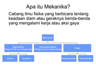


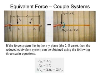
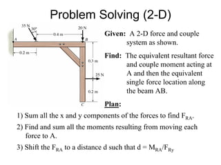
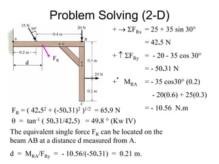

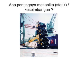
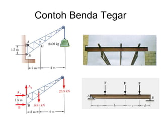
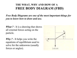
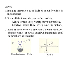
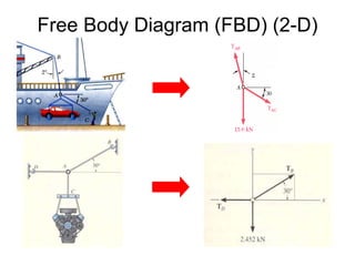


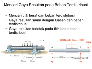
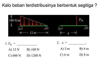
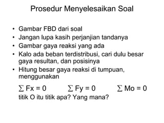

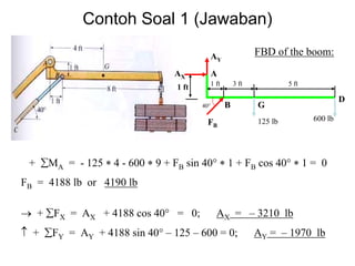


Three key concepts are discussed in the document: 1) Mechanics deals with the static and dynamic behavior of bodies under the influence of forces or torques. This includes rigid bodies, deformable bodies, and fluids. 2) A free body diagram shows all external forces acting on a particle or rigid body and is essential for writing equations of equilibrium. 3) The equilibrium of a particle in 2D involves applying equations that set the sum of forces in the x and y directions equal to zero to solve for unknown forces or angles.


![[7] resultan sistem gaya](https://cdn.slidesharecdn.com/ss_thumbnails/7resultansistemgaya-120404040925-phpapp02-thumbnail.jpg?width=640&height=640&fit=bounds)
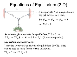
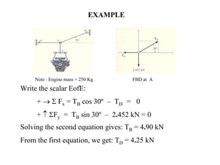
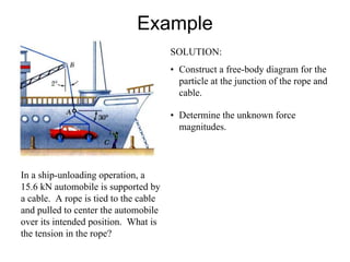
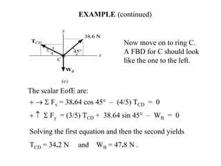
![[6] kesetimbangan partikel & fbd](https://cdn.slidesharecdn.com/ss_thumbnails/6kesetimbanganpartikelfbd-120404040738-phpapp01-thumbnail.jpg?width=640&height=640&fit=bounds)
![[3] vektor gaya](https://cdn.slidesharecdn.com/ss_thumbnails/3vektorgaya-120404040434-phpapp02-thumbnail.jpg?width=640&height=640&fit=bounds)


![[5] vektor gaya (part3)](https://cdn.slidesharecdn.com/ss_thumbnails/5vektorgayapart3-120404040622-phpapp02-thumbnail.jpg?width=640&height=640&fit=bounds)


