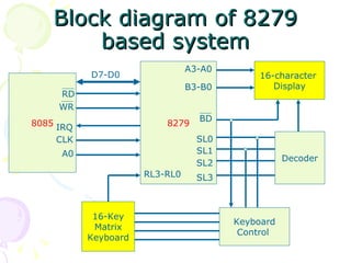
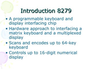
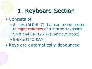
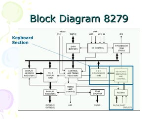
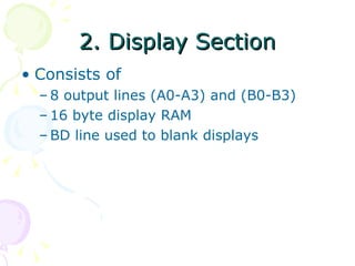
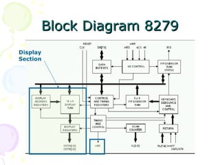
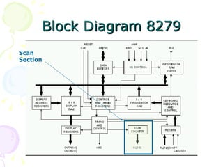
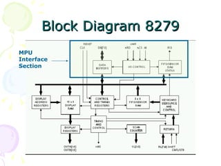
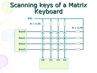
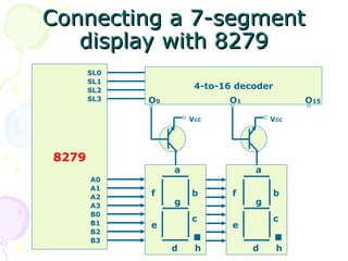
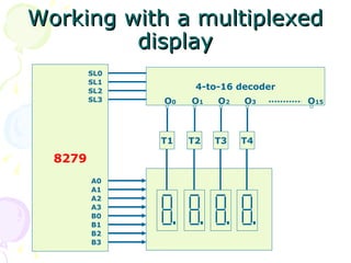
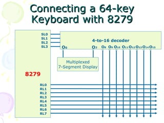
Programmable Keyboard/Display Interface THE 8279
Block diagram of 8279 based system 8085 8279 16-character  Display 16-Key Matrix Keyboard Keyboard Control  Decoder SL0 SL1 SL2 SL3 BD A3-A0 B3-B0 RL3-RL0 D7-D0 RD WR IRQ CLK A0
Introduction 8279 A programmable keyboard and display interfacing chip Hardware approach to interfacing a matrix keyboard and a multiplexed display Scans and encodes up to 64-key keyboard Controls up to 16-digit numerical display
8279 has 4 main segments Keyboard Scan Display MPU Interface
1. Keyboard Section Consists of 8 lines (RL0-RL7) that can be connected to  eight columns  of a matrix keyboard Shift and CNTL/STB (Control/Strobe) 8-byte FIFO RAM Keys are automatically debounced
Block Diagram 8279 Keyboard Section
2. Display Section Consists of 8 output lines (A0-A3) and (B0-B3) 16 byte display RAM BD line used to blank displays
Block Diagram 8279 Display Section
3. Scan Section Consists of Scan Counter Four scan lines (SL0-SL3) Used by keyboard and display section for proper functioning
Block Diagram 8279 Scan Section
MPU Interface section 8 bidirectional data lines (DB0-DB7) IRQ line RD line WR line CS line RESET line Buffer address line (A0)
Block Diagram 8279 MPU Interface Section
Pin Description 8279 A0: Selects data (0) or control/status (1) for reads and writes between micro and 8279. Output that blanks the displays. CLK: Used internally for timing. Max is 3 MHz. CN/ST: Control/strobe, connected to the control key on the keyboard. Chip select that enables programming, reading the keyboard, etc .  DB7-DB0: Consists of bi-directional pins that connect to data bus on micro .
IRQ: Interrupt request, becomes 1 when a key is pressed, data is available. OUT A3-A0/B3-B0: Outputs that sends data to the most significant/least significant nibble of display. :  Connects to micro's IORC or RD signal, reads data/status registers. RESET: Connects to system RESET. RL7-RL0: Return lines are inputs used to sense key depression in the keyboard matrix. Shift: Shift connects to Shift key on keyboard. SL3-SL0: Scan line outputs scan both the keyboard and displays.
Scanning keys of a Matrix Keyboard Vcc Row0 Row1 Row2 Row3 C0 C1 C2 C3 R = 4.7K R = 4.7K 0 1 2 3 4 5 6 7 8 9 A B C D E F
Connecting a 7-segment display with 8279 8279 4-to-16 decoder SL0 SL1 SL2 SL3 A0 A1 A2 A3 B0 B1 B2 B3 a b c d e f g h O 15 O 0 V CC a b c d e f g h V CC O 1
Working with a multiplexed display 8279 4-to-16 decoder SL0 SL1 SL2 SL3 A0 A1 A2 A3 B0 B1 B2 B3 O 15 O 0 T1 O 1 T2 O 2 T3 O 3 T4
Connecting a 64-key Keyboard with 8279 8279 4-to-16 decoder SL0 SL1 SL2 SL3 RL0 O 13 O 0 O 7 Multiplexed 7-Segment Display O 8 O 9 O 10 O 11 O 12 O 14 O 15 RL1 RL2 RL3 RL4 RL5 RL6 RL7

1205 Ppi 8279

  • 1.
  • 2.
    Block diagram of8279 based system 8085 8279 16-character Display 16-Key Matrix Keyboard Keyboard Control Decoder SL0 SL1 SL2 SL3 BD A3-A0 B3-B0 RL3-RL0 D7-D0 RD WR IRQ CLK A0
  • 3.
    Introduction 8279 Aprogrammable keyboard and display interfacing chip Hardware approach to interfacing a matrix keyboard and a multiplexed display Scans and encodes up to 64-key keyboard Controls up to 16-digit numerical display
  • 4.
    8279 has 4main segments Keyboard Scan Display MPU Interface
  • 5.
    1. Keyboard SectionConsists of 8 lines (RL0-RL7) that can be connected to eight columns of a matrix keyboard Shift and CNTL/STB (Control/Strobe) 8-byte FIFO RAM Keys are automatically debounced
  • 6.
    Block Diagram 8279Keyboard Section
  • 7.
    2. Display SectionConsists of 8 output lines (A0-A3) and (B0-B3) 16 byte display RAM BD line used to blank displays
  • 8.
    Block Diagram 8279Display Section
  • 9.
    3. Scan SectionConsists of Scan Counter Four scan lines (SL0-SL3) Used by keyboard and display section for proper functioning
  • 10.
    Block Diagram 8279Scan Section
  • 11.
    MPU Interface section8 bidirectional data lines (DB0-DB7) IRQ line RD line WR line CS line RESET line Buffer address line (A0)
  • 12.
    Block Diagram 8279MPU Interface Section
  • 13.
    Pin Description 8279A0: Selects data (0) or control/status (1) for reads and writes between micro and 8279. Output that blanks the displays. CLK: Used internally for timing. Max is 3 MHz. CN/ST: Control/strobe, connected to the control key on the keyboard. Chip select that enables programming, reading the keyboard, etc .  DB7-DB0: Consists of bi-directional pins that connect to data bus on micro .
  • 14.
    IRQ: Interrupt request,becomes 1 when a key is pressed, data is available. OUT A3-A0/B3-B0: Outputs that sends data to the most significant/least significant nibble of display. : Connects to micro's IORC or RD signal, reads data/status registers. RESET: Connects to system RESET. RL7-RL0: Return lines are inputs used to sense key depression in the keyboard matrix. Shift: Shift connects to Shift key on keyboard. SL3-SL0: Scan line outputs scan both the keyboard and displays.
  • 15.
    Scanning keys ofa Matrix Keyboard Vcc Row0 Row1 Row2 Row3 C0 C1 C2 C3 R = 4.7K R = 4.7K 0 1 2 3 4 5 6 7 8 9 A B C D E F
  • 16.
    Connecting a 7-segmentdisplay with 8279 8279 4-to-16 decoder SL0 SL1 SL2 SL3 A0 A1 A2 A3 B0 B1 B2 B3 a b c d e f g h O 15 O 0 V CC a b c d e f g h V CC O 1
  • 17.
    Working with amultiplexed display 8279 4-to-16 decoder SL0 SL1 SL2 SL3 A0 A1 A2 A3 B0 B1 B2 B3 O 15 O 0 T1 O 1 T2 O 2 T3 O 3 T4
  • 18.
    Connecting a 64-keyKeyboard with 8279 8279 4-to-16 decoder SL0 SL1 SL2 SL3 RL0 O 13 O 0 O 7 Multiplexed 7-Segment Display O 8 O 9 O 10 O 11 O 12 O 14 O 15 RL1 RL2 RL3 RL4 RL5 RL6 RL7