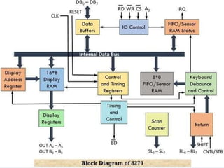
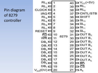
JAI NARAIN VYAS UNIVERSITY
JODHPUR ( RAJ. )
PHYSICS DEPARTMENT
PRESENTEDBY –
RAMNIWAS JAKHAR
SUBMITTEDTO :– DR.
s. k. sharma sir
DIGITAL ELECTRONICS AND
MICROPROCESSOR
ARCHITECTURE OF
SIMPLE I/O DEVICES :
HEX KEYBOARD, LED
DISPLAY WITH 8279
KEYBOARD-DISPLAY
INTERFACE
1. Keyboard
2. LED-Display
3. Hex keyboard , LED display with 8279
keyboard- display interface .
1. Keyboard :-
(1) Key switches :-
a. Mechanical key switches :-
- When plunzor is press, than movable plate take
physical contact with fitted metallic flate.
- When press than it’s set or 1.
- When key is remove, key return their original
position due to string.
• Disadvantage :- collision
of two metallic plate, it
take some time to settle
down , and time is known
as settle time.
b. Membrane key switches :-
- Sheet A : for column collector.
- Sheet B : Sheet with whole.
- Sheet C : for row collector.
- for every key, a particular whole sheet.
(2) Arrangement of key’s :-
- Key’s are arrange in matrix format.
- Microprocessor have 4x5 matrix key’s
arrangement.
- O/P port :- Port where m.p. sent data.
- I/P port :- Place where m.p. receive data.
- M.P. sent zero’s to 4-row’s.
- whenever a key is pressed, mean set, than m.p.
scan it, and get a binary code, for a particular
key.
2. LED DISPLAY :-
LED for display purpose.
(1) Types of LED for Display :-
a. 7- Segment :-
The 7- Segment display consists of seven LED’s
arranged in a rectangular fashion.
Called Segment because when illuminated the
Segment form part of a numerical digit, to be
displayed. Use :- numerous and few alphabets.
b. 18- Segment display :-
18- Segment display can be use for alpha
numerous and few special characters.
c. Matrix arrangement :- All alpha numerous and
special characters.
3. Hex keyboard , LED display with 8279
keyboard- display interface :-
8279 Hex keyboard and display controller :-
-8279 controller, packed in 40 pin dual in packed IC.
- Give interface to keyboard and 7- Segment LED
display with Intel microprocessor.
- 8279 can be divided into 3-parts :-
(1). Key board section.
(2). Display section.
(3). MPU interface unit.
(1). Key board section :-
In brief, 8279 KB section work is classified into
3 modes –
a. Scanned Keyboard Mode
b. Scanned Sensor Matrix
c. Stored Input .
(2). Display section :-
It deals with the output mode display-related
operations. This mode is further classified into two
output modes :
a. Display Scan
b. Display Entry .
(3) MPU interface unit :-
MPU interface consists of 8-bit bi-directional
data buffer bus.
I/O control : pins –
a. A0 : Used for distinguish between command
and data.
b. RD, WR : Status or read/ write operation.
c. by use of CS Low, device select by m.p.
Pin diagram
of 8279
controller
THANK YOU

Digital.pptx

  • 1.
    JAI NARAIN VYASUNIVERSITY JODHPUR ( RAJ. ) PHYSICS DEPARTMENT PRESENTEDBY – RAMNIWAS JAKHAR SUBMITTEDTO :– DR. s. k. sharma sir DIGITAL ELECTRONICS AND MICROPROCESSOR
  • 2.
    ARCHITECTURE OF SIMPLE I/ODEVICES : HEX KEYBOARD, LED DISPLAY WITH 8279 KEYBOARD-DISPLAY INTERFACE
  • 3.
    1. Keyboard 2. LED-Display 3.Hex keyboard , LED display with 8279 keyboard- display interface . 1. Keyboard :- (1) Key switches :- a. Mechanical key switches :- - When plunzor is press, than movable plate take physical contact with fitted metallic flate. - When press than it’s set or 1. - When key is remove, key return their original position due to string.
  • 4.
    • Disadvantage :-collision of two metallic plate, it take some time to settle down , and time is known as settle time.
  • 5.
    b. Membrane keyswitches :- - Sheet A : for column collector. - Sheet B : Sheet with whole. - Sheet C : for row collector. - for every key, a particular whole sheet.
  • 6.
    (2) Arrangement ofkey’s :- - Key’s are arrange in matrix format. - Microprocessor have 4x5 matrix key’s arrangement. - O/P port :- Port where m.p. sent data. - I/P port :- Place where m.p. receive data. - M.P. sent zero’s to 4-row’s. - whenever a key is pressed, mean set, than m.p. scan it, and get a binary code, for a particular key.
  • 8.
    2. LED DISPLAY:- LED for display purpose. (1) Types of LED for Display :- a. 7- Segment :- The 7- Segment display consists of seven LED’s arranged in a rectangular fashion. Called Segment because when illuminated the Segment form part of a numerical digit, to be displayed. Use :- numerous and few alphabets.
  • 9.
    b. 18- Segmentdisplay :- 18- Segment display can be use for alpha numerous and few special characters. c. Matrix arrangement :- All alpha numerous and special characters.
  • 10.
    3. Hex keyboard, LED display with 8279 keyboard- display interface :- 8279 Hex keyboard and display controller :- -8279 controller, packed in 40 pin dual in packed IC. - Give interface to keyboard and 7- Segment LED display with Intel microprocessor. - 8279 can be divided into 3-parts :- (1). Key board section. (2). Display section. (3). MPU interface unit.
  • 12.
    (1). Key boardsection :- In brief, 8279 KB section work is classified into 3 modes – a. Scanned Keyboard Mode b. Scanned Sensor Matrix c. Stored Input . (2). Display section :- It deals with the output mode display-related operations. This mode is further classified into two output modes : a. Display Scan b. Display Entry .
  • 13.
    (3) MPU interfaceunit :- MPU interface consists of 8-bit bi-directional data buffer bus. I/O control : pins – a. A0 : Used for distinguish between command and data. b. RD, WR : Status or read/ write operation. c. by use of CS Low, device select by m.p.
  • 14.
  • 15.