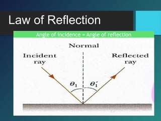
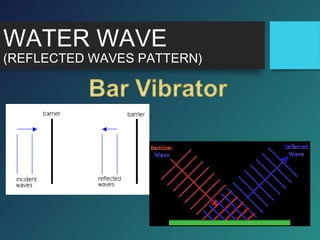
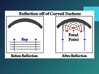
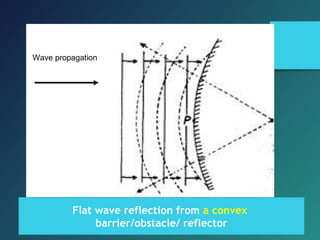
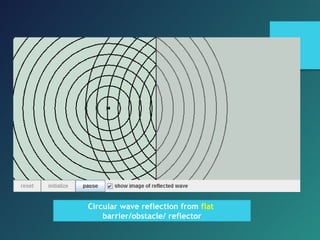
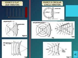
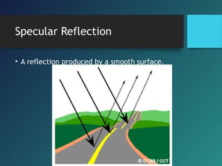
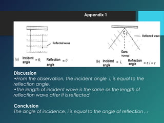
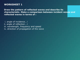
Here are the key points of comparison between incident and reflected waves:
i. Angle of incidence (i) = Angle of reflection (r)
ii. Wavelength (λ), frequency (f) and speed (v) remain the same.
iii. Direction of propagation - Reflected waves propagate in the opposite direction to the incident waves.
iv. Amplitude may decrease slightly due to absorption at the boundary. Otherwise, the wave remains the same.
v. Phase may be reversed depending on the type of boundary - either in phase or 180° out of phase.
vi. For perfect reflection from a smooth surface, the reflected wavefronts are parallel to the incident wavefronts.
To know that sound can be reflected, refracted, diffracted, and produces interference effects.
Know that sound is a wave because it can be reflected and refracted as with particles, diffraction and interference only occur with waves
Light is a transverse, electromagnetic wave that can be seen by humans. The wave nature of light was first illustrated through experiments on diffraction and interference. Like all electromagnetic waves, light can travel through a vacuum. The transverse nature of light can be demonstrated through polarization.
Overvoltages are an increase of voltage on the electric line, measure between two conductors, which can produce damage on the installations
and the electric equipments.
There are two different types: transient and permanent.
Permanent or power frequency overvoltages are characterized by relatively long duration (several cycles) There are usually caused by:
- Defect connection of the neutral.
- Power consumption lowered.
Transient overvoltages are very short duration increases in voltage
between two conductors or between a conductor and the ground. They
can be on account of atmospheric electrical discharges (lightning), by
switching or by electrical faults (contact with earth or short circuit).
Science Facts - Check our astonishing compiliation of random and science facts.
Visit us at http://mesmerizeus.com or follow us at https://www.facebook.com/mesmerizerz
Reflection and Refraction of Optical Rays.
For comments, please contact me at solo.hermelin@gmail.com.
For more presentations on different topics visit my website at http://www.solohermelin.com.
This presentation is in the Optics folder.
Elevating Tactical DDD Patterns Through Object CalisthenicsDorra BARTAGUIZ
After immersing yourself in the blue book and its red counterpart, attending DDD-focused conferences, and applying tactical patterns, you're left with a crucial question: How do I ensure my design is effective? Tactical patterns within Domain-Driven Design (DDD) serve as guiding principles for creating clear and manageable domain models. However, achieving success with these patterns requires additional guidance. Interestingly, we've observed that a set of constraints initially designed for training purposes remarkably aligns with effective pattern implementation, offering a more ‘mechanical’ approach. Let's explore together how Object Calisthenics can elevate the design of your tactical DDD patterns, offering concrete help for those venturing into DDD for the first time!
Neuro-symbolic is not enough, we need neuro-*semantic*Frank van Harmelen
Neuro-symbolic (NeSy) AI is on the rise. However, simply machine learning on just any symbolic structure is not sufficient to really harvest the gains of NeSy. These will only be gained when the symbolic structures have an actual semantics. I give an operational definition of semantics as “predictable inference”.
All of this illustrated with link prediction over knowledge graphs, but the argument is general.
UiPath Test Automation using UiPath Test Suite series, part 4DianaGray10
Welcome to UiPath Test Automation using UiPath Test Suite series part 4. In this session, we will cover Test Manager overview along with SAP heatmap.
The UiPath Test Manager overview with SAP heatmap webinar offers a concise yet comprehensive exploration of the role of a Test Manager within SAP environments, coupled with the utilization of heatmaps for effective testing strategies.
Participants will gain insights into the responsibilities, challenges, and best practices associated with test management in SAP projects. Additionally, the webinar delves into the significance of heatmaps as a visual aid for identifying testing priorities, areas of risk, and resource allocation within SAP landscapes. Through this session, attendees can expect to enhance their understanding of test management principles while learning practical approaches to optimize testing processes in SAP environments using heatmap visualization techniques
What will you get from this session?
1. Insights into SAP testing best practices
2. Heatmap utilization for testing
3. Optimization of testing processes
4. Demo
Topics covered:
Execution from the test manager
Orchestrator execution result
Defect reporting
SAP heatmap example with demo
Speaker:
Deepak Rai, Automation Practice Lead, Boundaryless Group and UiPath MVP
GDG Cloud Southlake #33: Boule & Rebala: Effective AppSec in SDLC using Deplo...James Anderson
Effective Application Security in Software Delivery lifecycle using Deployment Firewall and DBOM
The modern software delivery process (or the CI/CD process) includes many tools, distributed teams, open-source code, and cloud platforms. Constant focus on speed to release software to market, along with the traditional slow and manual security checks has caused gaps in continuous security as an important piece in the software supply chain. Today organizations feel more susceptible to external and internal cyber threats due to the vast attack surface in their applications supply chain and the lack of end-to-end governance and risk management.
The software team must secure its software delivery process to avoid vulnerability and security breaches. This needs to be achieved with existing tool chains and without extensive rework of the delivery processes. This talk will present strategies and techniques for providing visibility into the true risk of the existing vulnerabilities, preventing the introduction of security issues in the software, resolving vulnerabilities in production environments quickly, and capturing the deployment bill of materials (DBOM).
Speakers:
Bob Boule
Robert Boule is a technology enthusiast with PASSION for technology and making things work along with a knack for helping others understand how things work. He comes with around 20 years of solution engineering experience in application security, software continuous delivery, and SaaS platforms. He is known for his dynamic presentations in CI/CD and application security integrated in software delivery lifecycle.
Gopinath Rebala
Gopinath Rebala is the CTO of OpsMx, where he has overall responsibility for the machine learning and data processing architectures for Secure Software Delivery. Gopi also has a strong connection with our customers, leading design and architecture for strategic implementations. Gopi is a frequent speaker and well-known leader in continuous delivery and integrating security into software delivery.
Generating a custom Ruby SDK for your web service or Rails API using Smithyg2nightmarescribd
Have you ever wanted a Ruby client API to communicate with your web service? Smithy is a protocol-agnostic language for defining services and SDKs. Smithy Ruby is an implementation of Smithy that generates a Ruby SDK using a Smithy model. In this talk, we will explore Smithy and Smithy Ruby to learn how to generate custom feature-rich SDKs that can communicate with any web service, such as a Rails JSON API.
UiPath Test Automation using UiPath Test Suite series, part 3DianaGray10
Welcome to UiPath Test Automation using UiPath Test Suite series part 3. In this session, we will cover desktop automation along with UI automation.
Topics covered:
UI automation Introduction,
UI automation Sample
Desktop automation flow
Pradeep Chinnala, Senior Consultant Automation Developer @WonderBotz and UiPath MVP
Deepak Rai, Automation Practice Lead, Boundaryless Group and UiPath MVP
Software Delivery At the Speed of AI: Inflectra Invests In AI-Powered QualityInflectra
In this insightful webinar, Inflectra explores how artificial intelligence (AI) is transforming software development and testing. Discover how AI-powered tools are revolutionizing every stage of the software development lifecycle (SDLC), from design and prototyping to testing, deployment, and monitoring.
Learn about:
• The Future of Testing: How AI is shifting testing towards verification, analysis, and higher-level skills, while reducing repetitive tasks.
• Test Automation: How AI-powered test case generation, optimization, and self-healing tests are making testing more efficient and effective.
• Visual Testing: Explore the emerging capabilities of AI in visual testing and how it's set to revolutionize UI verification.
• Inflectra's AI Solutions: See demonstrations of Inflectra's cutting-edge AI tools like the ChatGPT plugin and Azure Open AI platform, designed to streamline your testing process.
Whether you're a developer, tester, or QA professional, this webinar will give you valuable insights into how AI is shaping the future of software delivery.
Epistemic Interaction - tuning interfaces to provide information for AI supportAlan Dix
Paper presented at SYNERGY workshop at AVI 2024, Genoa, Italy. 3rd June 2024
https://alandix.com/academic/papers/synergy2024-epistemic/
As machine learning integrates deeper into human-computer interactions, the concept of epistemic interaction emerges, aiming to refine these interactions to enhance system adaptability. This approach encourages minor, intentional adjustments in user behaviour to enrich the data available for system learning. This paper introduces epistemic interaction within the context of human-system communication, illustrating how deliberate interaction design can improve system understanding and adaptation. Through concrete examples, we demonstrate the potential of epistemic interaction to significantly advance human-computer interaction by leveraging intuitive human communication strategies to inform system design and functionality, offering a novel pathway for enriching user-system engagements.
Slack (or Teams) Automation for Bonterra Impact Management (fka Social Soluti...Jeffrey Haguewood
Sidekick Solutions uses Bonterra Impact Management (fka Social Solutions Apricot) and automation solutions to integrate data for business workflows.
We believe integration and automation are essential to user experience and the promise of efficient work through technology. Automation is the critical ingredient to realizing that full vision. We develop integration products and services for Bonterra Case Management software to support the deployment of automations for a variety of use cases.
This video focuses on the notifications, alerts, and approval requests using Slack for Bonterra Impact Management. The solutions covered in this webinar can also be deployed for Microsoft Teams.
Interested in deploying notification automations for Bonterra Impact Management? Contact us at sales@sidekicksolutionsllc.com to discuss next steps.
4. When an object, like a ball, is thrown
against a rigid wall it will…?
ball
wall
This "reflection" of the object
can be analyzed in terms of
momentum and energy
conservation
If the collision between ball and wall is
perfectly ELASTIC, then all the
incident energy and momentum is
reflected, and the ball bounces back
with the same speed
If the collision is INELASTIC, then the wall (or ball)
absorbs some of the incident energy and
momentum and the ball does not bounce back with the
same speed.
5. Waves also carry energy and momentum
whenever a wave
encounters an obstacle,
they are reflected by the
obstacle
reflection of waves is responsible for
echoes, radar detectors, and for allowing
standing waves which are so important
to sound production in musical
instruments.
6. Reflection
When a wave reaches a
boundary it is:
•Partially reflected (bounces off
surface)
•Partially transmitted through
surface.
19. LIGHT WAVES
(REFLECTED WAVES)
• When rays of light strike any surface the rays
are reflected , unless the surface is black, when
they are absorbed.
• The reflection depend on how smooth the
surfaces are. Good mirrors reflect well over 90%
of the light that reaches them, with only a small
amount being absorbed.
• A plane mirror is a flat smooth surface which
reflects regularly most of the light falling on it.
20. • The phenomenon of reflection of light obeys the
law of reflection.
(a) The angle of incidence is equal to the angle of
reflection.
(b) The incident wave, the reflected wave and the normal
lie in the same plane.
• It also can be seen that
(a) The size of the image = the size of the object
(b) The distance of the image = the distance of the object
25. Reflection from a Plane Mirror
di=do
hi=hoVirtual image
(dotted lines show
26. Step by step to Draw image…
Please refer to the text book…
Learn and practice step by step how to draw the
images…
27. Type of Image formed by a
plane mirror
• Laterally inverted
• Same size as the object
• Virtual and
• As far behind the mirror as
the object is in front of it
Refer pg. 133 in
your txt bk.
(English Ver.)
28. What is the minimum mirror
height required for a person to
see their full self in the mirror?
31. Curved mirrors can make things look
smaller or BIGGER.
C = center of curvature
(center of sphere of the
mirror)
R = The distance between C
and the mirror is called the
radius of curvature
f = FP (FP = ½ CP)
F = Principal focus
Principal Axis = connecting
line from the centre of
curvature to point P
32. Application Concave
Mirrors
torches,
search-lights and vehicles headlights to get powerful
parallel beams of light.
They are often used as shaving mirrors to see a larger
image of the face.
The dentists use concave mirrors to see large images of
the teeth of patients.
Large concave mirrors are used to concentrate sunlight
to produce heat in solar furnaces.
35. Application Convex
Mirrors
commonly used as rear-view (wing) mirrors in
vehicles.
These mirrors are fitted on the sides of the
vehicle, enabling the driver to see traffic behind
him/her to facilitate safe driving.
Convex mirrors are preferred because they
always give an erect, though diminished, image.
Also, they have a wider field of view as they are
curved outwards.
Thus, convex mirrors enable the driver to view
much large area than would be possible with a
plane mirror
36. Assignment (A):
If you were a sound engineer, what is the modification that you
have to do to improve a recording studio. In your explanations ,
include steps to overcome sound reflection problems.
Assignment (B):
You are engaged by an interior design company to help to design a
café in the town. You are required to make the café look more
spacious. Explain how to make the hall look bigger by fixing mirrors
on the wall.
REFLECTION OF
SOUND WAVE
37. Assignment (C):
Make a mind map of reflection of wave. Make sure all
important points are included. Use a manila card or a
mahjong paper.
Assignment (D):
Make a table of comparison of reflection waves of water
waves, light waves and also sound waves.
38. Experiments of Reflection
of Waves
Aim : To observe and describe the reflection of water waves
in terms of the angle of incidence, angle of reflection and
the wavelength.
Apparatus : ripple tank, straight dipper, straight reflector,
stroboscope, white mahjong paper, metre rule, power
supply, rheostat.
39.
40. Procedure :
1. Set up the apparatus as shown in the figure above.
2. Pour water into the ripple tank to a depth of about
1 cm and adjust the stands to ensure the depth of
the water in the tank is uniform.
3. Lower the straight dipper until it just touches the
surface of the water.
4. Place a straight reflector parallel to the dipper, 30
cm away.
5. Switch on the lamp and the motor. Adjust the
frequency of the motor by sliding the rheostat so
that the image of the wave is clear.
41. 6. Use the stroboscope to freeze the image of the
wave form.
7. Mark the image on the white paper.
8. Measure the angle of incidence, angle of
reflection, wavelength of the incident waves and
reflected waves.
9. Replace the paper, repeat steps 4 – 8 with the
angle between the reflector and the dipper at 15º,
30º ,45º and 60º.
10. Tabulate your data.
11. Deduce the relationship between
i. the angle of incidence and angle of reflection;
ii. The wavelength of the incident waves and reflected
waves.
42. Appendix 1
Discussion
•From the observation, the incident angle i, is equal to the
reflection angle.
•The length of incident wave is the same as the length of
reflection wave after it is reflected
Conclusion
The angle of incidence, i is equal to the angle of reflection , r
43. A simple experiment of reflection of sound waves
Equipment and materials:
Stopwatch, 2 cardboard tube with length 50 cm, smooth wall,
smooth/soft wood
Figure 1
Procedure
1. Place a stop watch at the end of a hollow tube.
2. The tube is placed at an angle to a reflecting surface as shown in the above
figure.
3. Keep a smooth wood vertical on the table top.
4. Place another hollow tube on the other side of the smooth wood and hold it
close to ear.
5. Adjust the angle of the second tube until a loud ticking is heard.
Make a conclusion of this activity.
44. Appendix 2 (Sound Wave)
Results
It is observed that the loudest ticking sound is heard when the angle of
incident is the same as the angle of reflection.
Discussion:
1.Soft board/wood is used to avoid the ticking sound of the stopwatch
from being heard directly by the listener’s ears.
2.Smooth wall reflects sound waves more efficiently.
Conclusion
The angle of incidence , i is equal to the angle of reflection , r.
45. WORKSHEET 1
Draw the pattern of reflected waves and describe its
characteristic. Make a comparison between incident waves and
reflected waves in terms of :
i. angle of incidence , i
ii. angle of reflection , r
iii. wavelength, frequency and speed
iv. direction of propagation of the wave