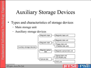
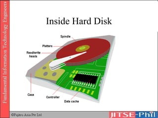
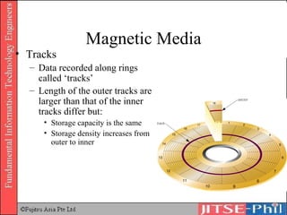
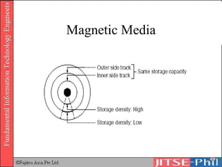
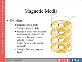
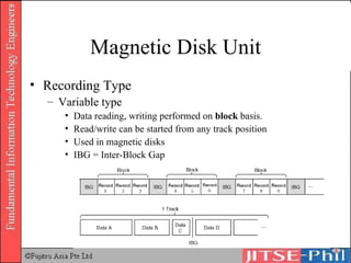
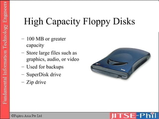
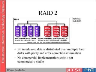
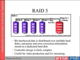
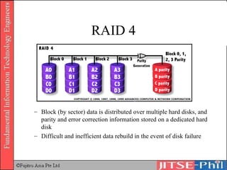
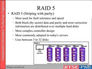
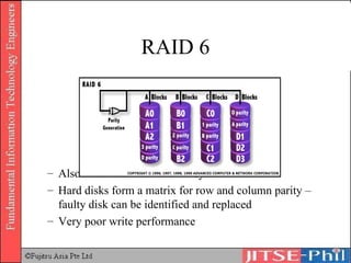
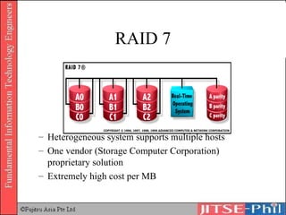
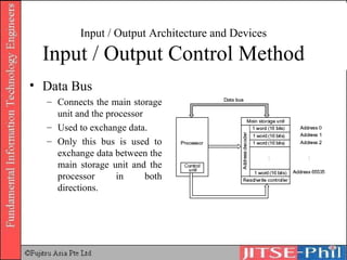
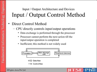
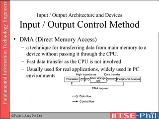
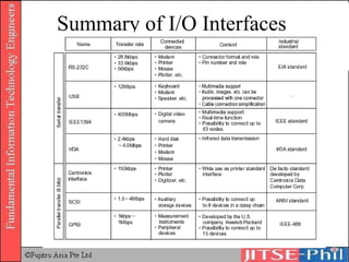
Part 2 Computer Systems (Aux and I/O) Hardware (Text No. 1 Chapter 2)
HARDWARE 2.4 Auxiliary storage devices 2.5 Input/output architecture and devices
Auxiliary Storage Devices Types and characteristics of storage devices Main storage unit Auxiliary storage devices
Magnetic Tape
Magnetic Tape Type 0 Original ferric-oxide tape Very rarely seen these days Type 1 Standard ferric-oxide tape Also referred to as "normal bias"
Magnetic Tape Type 2 "Chrome" or CrO 2  tape The ferric-oxide particles are mixed with chromium dioxide Type 4 "Metal" tape Metallic particles rather than metal-oxide particles are used in the tape
Magnetic Disk Unit Devices that store data using magnetic disks.  Most widely used auxiliary storage device Magnetic disks for personal computers or workstations are also called fixed disks or hard disks but the mechanism is the same.
Magnetic Disk Unit
Opening Up Hard Disk
Platters and Heads
Inside Hard Disk
Magnetic Media Tracks Data recorded along rings called ‘tracks’ Length of the outer tracks are larger than that of the inner tracks differ but: Storage capacity is the same Storage density increases from outer to inner
Magnetic Media
Magnetic Media Cylinders In magnetic disk units Multiple magnetic disks Groups of tracks with the same radius on each of the disks is set as one data storage area called a ‘cylinder’ Makes for more efficient data retrieval Multiple fixed arm magnetic heads
Magnetic Media
Inside Hard disk
Magnetic Disk Structure
Magnetic Media Storage Capacity  = storage capacity of 1 track *  number of tracks per cylinder *  number of cylinders of the magnetic disk
Calculating Storage Capacity Specifications Number of cylinders: 800 Number of tracks per cylinder: 19 Storage capacity per track: 20,000 bytes
Calculating Storage Capacity Specifications Number of cylinders: 800 Number of tracks per cylinder: 19 Storage capacity per track: 20,000 bytes Calculations Storage capacity per cylinder 20,000 bytes * 19 tracks = 380,000 bytes/cylinder = app. 380KB Storage capacity of disk  380KB * 800 cylinders = 304,000 KB = app. 304 MB
Magnetic Disk Unit Recording Type Variable type Data reading, writing performed on  block  basis. Read/write can be started from any track position Used in magnetic disks IBG = Inter-Block Gap
Calculating Storage Capacity (Blocking) Calculate the number of cylinders required when 80,000 records of 200 bytes each are stored in a sequential access file of 10 records/block. Blocking cannot be extended over multiple tracks. Number of cylinders : 400 Number of tracks/cylinder : 19 Storage capacity/track : 20,000 bytes Inter-block gap (IBG)  : 120 bytes
Calculating Storage Capacity (Blocking) Number of blocks for the whole file = number of records/blocking factor 80,000 / 10 = 8,000 blocks Length of 1 block, including the IBG 200 bytes/record * 10 records/block + 120 bytes/block = 2,120 bytes/block Number of blocks on 1 track 20,000 bytes/track / 2,120 bytes/block = app. 9.43 blocks/track Because b locking cannot be extended over multiple tracks, floor(9.43) = 9 blocks/track Number of tracks for the whole file 8,000 blocks / 9 blocks/track = app. 888.88 tracks Ceil(888.88) = 889 tracks Number of cylinders required to write the whole file = number of tracks / number of tracks/cylinder 889 / 19 = app. 46.78 cylinders Ceil (46.78) = 47 cylinders.
Magnetic Media Structure and operation principles Sector type Each track divided into approximately 20 small sectors.  Reading/writing specified with sector number of selected track. Used in hard disks and floppy disks.
Magnetic Disk Structure
Magnetic Disk Parity check Magnetic head reads/writes data to track bit by bit appending an extra bit for parity check. Defragmentation Data written on hard disks are not contiguous resulting in slow access time.  Defragmentation  will arrange data contiguously thereby speeding up read/write time
Magnetic Disk Access is the generic term for the act of reading specific data from the magnetic disk and writing it on a specific cylinder or track. Access time is calculated through the addition of the following: Seek time Search time Data transfer time
Magnetic Disk Seek time Refers to the time a program or device takes to locate a particular piece of data. For disk drives, the terms  seek time  and  access time  are often used interchangeably. Technically speaking, however, the access time is often longer than seek time because it includes a brief latency period.
Magnetic Disk Search time or latency Lapse of time until target data reaches the magnetic head position
Magnetic Disk Data transfer time Time elapsed between when the magnetic head data access starts and when the transfer is completed
Access Time Access Time of Magnetic Disk Unit  = Average Seek Time + Average Search Time + Data Transfer Time
Calculating Access Time Specifications Capacity/track : 45,000 bytes Rotation speed : 2,500 rpm Average seek time : 10 s Find the access time (ms) for 15,000 bytes of data
Calculation Average search time Revolution speed = 3,000 rpm 3,000 rev in 60 sec n(revolutions) in 1 second = 3000 / 60 = 50 rev/sec 1 rev in (1/50)sec = 0.02 sec/revolution = 20ms/rev Average search time = 20ms / 2 =  10 ms
Calculating Access Time Data Transfer Speed In 1 revolution, the information contained in 1 track passes through the magnetic disk head The disk makes 50 rev/sec Data transfer speed = 50 tracks/sec * 15,000 bytes/track = 750,000 = 750 * 10 3  bytes/sec Data transfer time for 9,000 bytes of data = (9*10 3 )/(750*10 3 ) = 0.012 sec = 12 ms Access Time = Average Seek Time + Average Search Time + Data Transfer Time 20ms + 10ms + 12ms =  42  ms
Floppy Disk Track  – Concentric ring of data on a side of a disk. Sector  – A subset of a track, similar to wedge or a slice of pie.
Floppy Disk Recording method is sector type. Within the outer protective casing is a circular flexible disk, hence “floppy” Low priced storage unit and easily transported, it is widely used.
Floppy Disk Structure
Floppy Disk Read/Write Located on both sides of a diskette The heads are not directly opposite each other The same head is used for reading/writing, while a second wider head is used for erasing a track just prior to it being written.
Floppy Disk Stepper Motor Makes a precise number of stepped revolutions to move the read/write head assembly to the proper track position The read/write head assembly is fastened to the stepper motor shaft
Floppy Disk Storage capacity =  Storage capacity per sector * Number of sectors per track * Number of tracks per side * Number of sides (One side or both sides)
Calculating Floppy Disk Capacity Specifications Sides available for use:  2 sides Track number/side:  80 tracks Sector number/track:  9 sectors Storage capacity/sector:  1,024 bytes Storage capacity of 1 track 1,024 bytes/sector    9 sectors/track = 9,216 bytes/track Storage capacity of 1 side is as follows: 9,216 bytes/track    80 tracks = 737,280 bytes = app. 737kB Both sides used: 737kB    2 = 1,474kB = app. 1.44MB
High Capacity Floppy Disks 100 MB or greater capacity Store large files such as graphics, audio, or video Used for backups SuperDisk drive Zip drive
Optical Disk (CD, DVD) Unit Optical disk units Store/save image processing data of extremely large volume or as storage devices of large volume packaged software.  These devices can store large volumes of data through a mechanism that reads out information using light reflection Widely used form of multimedia storage and distribution
CD-ROM Compact disc read-only memory Can contain text, graphics, and video as well as sound Cannot be erased or modified Use CD-ROM drive or CD-ROM player to read Holds about 650-850 MB Used to distribute software
Optical Disk (CD, DVD) Unit Music (Audio) CD (CDA) CD-ROM CD-G (CD-Graphic) for image data CD-I (CD-Interactive) for interactive applications Photo-CD CD-R (CD-Recordable) CD-RW (CD-Rewritable) Multi-session
CD-ROM Structure
CD Surface
Reading from CD-ROM
Disney World on CD-ROM
CD-ROM Performance Seek time Slow compared to magnetic disks due to heavy lens in the read head and the spiral structure Transfer rate Expressed in numeric values that represent how much data can be transferred in comparison with audio CDs.  Audio CD player : 150kB/s CD-ROM units with transfer speeds 2 times or 3 times as fast as the transfer rate for audio CDs began to be developed and today the transfer rate has reached levels of 50x.
Optical Disk Specifications Red Book Basic CD standard. Describes physical specifications of the CD Yellow Book Basic CDROM standard. Physical specifications of the CDROM Green Book Defines physical structure of CD-I (CD Interactive) Orange Book Defines physical structure of the CD-R (CD-Recordable)
DVD DVD (Digital Versatile Disk or Digital Video Disk) Capable of storing up to 2 hours (or more, depending on standards used) of animated images and audio data Can be thought of as layering CD-ROMs one on top of the other
Hollywood on DVD
DVD Structure Uses MPEG2 compression technology High quality audio/video Variations DVD-ROM DVD-R DVD-RAM Regional encoding
DVD Surface
DVD Recording
DVD Capacity Single layer single sided recording:  4.7 GB Dual layer single sided recording:  8.5 GB Single layer dual sided recording:  9.4 GB Dual layer dual sided recording:  17 GB
CD versus DVD Note that double layer is only applicable to DVD. 440 nanometers NA Min Pit Length (Double layer) 400 nanometers 830 nanometers Min Pit Length (Single layer) 740 nanometers 1600 nanometers Track Pitch DVD CD Specification
Semiconductor Disk Unit Storage unit of high speed and large capacity Uses flash memories and other devices Usually used in high-end mainframe computers as a storage unit positioned between the main storage unit and the auxiliary storage devices.  Several G bytes of storage capacity Access time is 1/100th that of the magnetic disk unit
Flash Memory
RAID  High reliability and high performance of storage becoming increasingly important Especially in real-time networked environments Redundant Arrays of Inexpensive Disks Fault-tolerant Use from 2 to 32 disks in an array Most commonly used RAID 0, RAID 1 and RAID 5 Rapid data recovery (rollback) in the event of a disk failure Can be implemented in hardware which is the preferred method or software which is cheaper
RAID 0  Striping Data is stripped among all available disks Between 2 and 32 disks are used.  Fastest read/write No redundancy, hence no fault-tolerance One disk failure, all data in array are lost Useful for video production and editing, image editing, and any application requiring high bandwidth
RAID 1 Disk Mirroring/Duplexing Uses 2 drives with same capacity where same content recorded on two hard disks concurrently Useful for critical mission applications Slowest of the RAID levels Fault tolerant - if one disk fails, data can be recovered from the other disk Single point of failure. If controller fails, both disks will be lost.
RAID 2 Bit interleaved data is distributed over multiple hard disks with parity and error correction information No commercial implementations exist / not commercially viable Hamming Code ECC
RAID 3 Bit interleaved data is distributed over multiple hard disks, and parity and error correction information stored on a dedicated hard disk Controller design is fairly complex Useful for video production and live streaming
RAID 4 Block (by sector) data is distributed over multiple hard disks, and parity and error correction information stored on a dedicated hard disk Difficult and inefficient data rebuild in the event of disk failure
RAID 5 RAID 5 (Striping with parity) Most used for fault tolerance and speed Both block (by sector) data and parity and error correction information are distributed over multiple hard disks Most complex controller design Most commonly adopted in today's servers Uses between 3 to 32 disks
RAID 6 Also known as fault tolerant system Hard disks form a matrix for row and column parity – faulty disk can be identified and replaced Very poor write performance
RAID 7 Heterogeneous system supports multiple hosts One vendor (Storage Computer Corporation) proprietary solution Extremely high cost per MB
I/O Architecture and Devices Input/output control method Bus Control bus Data bus Direct control method DMA (Direct Access Memory) method
I/O Architecture and Devices I/O Control Method Bus A collection of wires through which data is transmitted from one part of a computer to another   All buses consist of two parts -- an address bus and a data bus. The data bus transfers actual data whereas the address bus transfers information about where the data should go The size of a bus, known as its  width,  determines how much data can be transmitted at one time. For example, a 16-bit bus can transmit 16 bits of data, whereas a 32-bit bus can transmit 32 bits of data.  Every bus has a clock speed measured in MHz
Bus
Bus
Input / Output Architecture and Devices Input / Output Control Method Address Bus A collection of wires connecting the CPU with main memory that is used to identify particular locations (addresses) in main memory. The width of the address bus (that is, the number of wires) determines how many unique memory locations can be addressed
Input / Output Architecture and Devices Input / Output Control Method Control Bus Connects control unit and RAM. Used for transmission of instruction signals to RAM unit from control unit
Input / Output Architecture and Devices Input / Output Control Method Data Bus Connects the main storage unit and the processor Used to exchange data. Only this bus is used to exchange data between the main storage unit and the processor in both directions.
Input / Output Architecture and Devices Input / Output Control Method Direct Control Method CPU directly controls input/output operations  Data exchange is performed through the processor Processor cannot perform the next action till the input/output operation is completed Inefficient; this method is not widely used
Input / Output Architecture and Devices Input / Output Control Method DMA (Direct Memory Access) a technique for transferring data from main memory to a device without passing it through the CPU.  Fast data transfer as the CPU is not involved Usually used for real applications, widely used in PC environments
Input / Output Architecture and Devices Input/output interfaces Serial interface RS-232C USB IEEE 1394 Parallel interface Centronics interface SCSI GPIB
Summary of I/O Interfaces

12. Computer Systems Hardware 2

  • 1.
    Part 2 ComputerSystems (Aux and I/O) Hardware (Text No. 1 Chapter 2)
  • 2.
    HARDWARE 2.4 Auxiliarystorage devices 2.5 Input/output architecture and devices
  • 3.
    Auxiliary Storage DevicesTypes and characteristics of storage devices Main storage unit Auxiliary storage devices
  • 4.
  • 5.
    Magnetic Tape Type0 Original ferric-oxide tape Very rarely seen these days Type 1 Standard ferric-oxide tape Also referred to as "normal bias"
  • 6.
    Magnetic Tape Type2 "Chrome" or CrO 2 tape The ferric-oxide particles are mixed with chromium dioxide Type 4 "Metal" tape Metallic particles rather than metal-oxide particles are used in the tape
  • 7.
    Magnetic Disk UnitDevices that store data using magnetic disks. Most widely used auxiliary storage device Magnetic disks for personal computers or workstations are also called fixed disks or hard disks but the mechanism is the same.
  • 8.
  • 9.
  • 10.
  • 11.
  • 12.
    Magnetic Media TracksData recorded along rings called ‘tracks’ Length of the outer tracks are larger than that of the inner tracks differ but: Storage capacity is the same Storage density increases from outer to inner
  • 13.
  • 14.
    Magnetic Media CylindersIn magnetic disk units Multiple magnetic disks Groups of tracks with the same radius on each of the disks is set as one data storage area called a ‘cylinder’ Makes for more efficient data retrieval Multiple fixed arm magnetic heads
  • 15.
  • 16.
  • 17.
  • 18.
    Magnetic Media StorageCapacity = storage capacity of 1 track * number of tracks per cylinder * number of cylinders of the magnetic disk
  • 19.
    Calculating Storage CapacitySpecifications Number of cylinders: 800 Number of tracks per cylinder: 19 Storage capacity per track: 20,000 bytes
  • 20.
    Calculating Storage CapacitySpecifications Number of cylinders: 800 Number of tracks per cylinder: 19 Storage capacity per track: 20,000 bytes Calculations Storage capacity per cylinder 20,000 bytes * 19 tracks = 380,000 bytes/cylinder = app. 380KB Storage capacity of disk 380KB * 800 cylinders = 304,000 KB = app. 304 MB
  • 21.
    Magnetic Disk UnitRecording Type Variable type Data reading, writing performed on block basis. Read/write can be started from any track position Used in magnetic disks IBG = Inter-Block Gap
  • 22.
    Calculating Storage Capacity(Blocking) Calculate the number of cylinders required when 80,000 records of 200 bytes each are stored in a sequential access file of 10 records/block. Blocking cannot be extended over multiple tracks. Number of cylinders : 400 Number of tracks/cylinder : 19 Storage capacity/track : 20,000 bytes Inter-block gap (IBG) : 120 bytes
  • 23.
    Calculating Storage Capacity(Blocking) Number of blocks for the whole file = number of records/blocking factor 80,000 / 10 = 8,000 blocks Length of 1 block, including the IBG 200 bytes/record * 10 records/block + 120 bytes/block = 2,120 bytes/block Number of blocks on 1 track 20,000 bytes/track / 2,120 bytes/block = app. 9.43 blocks/track Because b locking cannot be extended over multiple tracks, floor(9.43) = 9 blocks/track Number of tracks for the whole file 8,000 blocks / 9 blocks/track = app. 888.88 tracks Ceil(888.88) = 889 tracks Number of cylinders required to write the whole file = number of tracks / number of tracks/cylinder 889 / 19 = app. 46.78 cylinders Ceil (46.78) = 47 cylinders.
  • 24.
    Magnetic Media Structureand operation principles Sector type Each track divided into approximately 20 small sectors. Reading/writing specified with sector number of selected track. Used in hard disks and floppy disks.
  • 25.
  • 26.
    Magnetic Disk Paritycheck Magnetic head reads/writes data to track bit by bit appending an extra bit for parity check. Defragmentation Data written on hard disks are not contiguous resulting in slow access time. Defragmentation will arrange data contiguously thereby speeding up read/write time
  • 27.
    Magnetic Disk Accessis the generic term for the act of reading specific data from the magnetic disk and writing it on a specific cylinder or track. Access time is calculated through the addition of the following: Seek time Search time Data transfer time
  • 28.
    Magnetic Disk Seektime Refers to the time a program or device takes to locate a particular piece of data. For disk drives, the terms seek time and access time are often used interchangeably. Technically speaking, however, the access time is often longer than seek time because it includes a brief latency period.
  • 29.
    Magnetic Disk Searchtime or latency Lapse of time until target data reaches the magnetic head position
  • 30.
    Magnetic Disk Datatransfer time Time elapsed between when the magnetic head data access starts and when the transfer is completed
  • 31.
    Access Time AccessTime of Magnetic Disk Unit = Average Seek Time + Average Search Time + Data Transfer Time
  • 32.
    Calculating Access TimeSpecifications Capacity/track : 45,000 bytes Rotation speed : 2,500 rpm Average seek time : 10 s Find the access time (ms) for 15,000 bytes of data
  • 33.
    Calculation Average searchtime Revolution speed = 3,000 rpm 3,000 rev in 60 sec n(revolutions) in 1 second = 3000 / 60 = 50 rev/sec 1 rev in (1/50)sec = 0.02 sec/revolution = 20ms/rev Average search time = 20ms / 2 = 10 ms
  • 34.
    Calculating Access TimeData Transfer Speed In 1 revolution, the information contained in 1 track passes through the magnetic disk head The disk makes 50 rev/sec Data transfer speed = 50 tracks/sec * 15,000 bytes/track = 750,000 = 750 * 10 3 bytes/sec Data transfer time for 9,000 bytes of data = (9*10 3 )/(750*10 3 ) = 0.012 sec = 12 ms Access Time = Average Seek Time + Average Search Time + Data Transfer Time 20ms + 10ms + 12ms = 42 ms
  • 35.
    Floppy Disk Track – Concentric ring of data on a side of a disk. Sector – A subset of a track, similar to wedge or a slice of pie.
  • 36.
    Floppy Disk Recordingmethod is sector type. Within the outer protective casing is a circular flexible disk, hence “floppy” Low priced storage unit and easily transported, it is widely used.
  • 37.
  • 38.
    Floppy Disk Read/WriteLocated on both sides of a diskette The heads are not directly opposite each other The same head is used for reading/writing, while a second wider head is used for erasing a track just prior to it being written.
  • 39.
    Floppy Disk StepperMotor Makes a precise number of stepped revolutions to move the read/write head assembly to the proper track position The read/write head assembly is fastened to the stepper motor shaft
  • 40.
    Floppy Disk Storagecapacity = Storage capacity per sector * Number of sectors per track * Number of tracks per side * Number of sides (One side or both sides)
  • 41.
    Calculating Floppy DiskCapacity Specifications Sides available for use: 2 sides Track number/side: 80 tracks Sector number/track: 9 sectors Storage capacity/sector: 1,024 bytes Storage capacity of 1 track 1,024 bytes/sector  9 sectors/track = 9,216 bytes/track Storage capacity of 1 side is as follows: 9,216 bytes/track  80 tracks = 737,280 bytes = app. 737kB Both sides used: 737kB  2 = 1,474kB = app. 1.44MB
  • 42.
    High Capacity FloppyDisks 100 MB or greater capacity Store large files such as graphics, audio, or video Used for backups SuperDisk drive Zip drive
  • 43.
    Optical Disk (CD,DVD) Unit Optical disk units Store/save image processing data of extremely large volume or as storage devices of large volume packaged software. These devices can store large volumes of data through a mechanism that reads out information using light reflection Widely used form of multimedia storage and distribution
  • 44.
    CD-ROM Compact discread-only memory Can contain text, graphics, and video as well as sound Cannot be erased or modified Use CD-ROM drive or CD-ROM player to read Holds about 650-850 MB Used to distribute software
  • 45.
    Optical Disk (CD,DVD) Unit Music (Audio) CD (CDA) CD-ROM CD-G (CD-Graphic) for image data CD-I (CD-Interactive) for interactive applications Photo-CD CD-R (CD-Recordable) CD-RW (CD-Rewritable) Multi-session
  • 46.
  • 47.
  • 48.
  • 49.
  • 50.
    CD-ROM Performance Seektime Slow compared to magnetic disks due to heavy lens in the read head and the spiral structure Transfer rate Expressed in numeric values that represent how much data can be transferred in comparison with audio CDs. Audio CD player : 150kB/s CD-ROM units with transfer speeds 2 times or 3 times as fast as the transfer rate for audio CDs began to be developed and today the transfer rate has reached levels of 50x.
  • 51.
    Optical Disk SpecificationsRed Book Basic CD standard. Describes physical specifications of the CD Yellow Book Basic CDROM standard. Physical specifications of the CDROM Green Book Defines physical structure of CD-I (CD Interactive) Orange Book Defines physical structure of the CD-R (CD-Recordable)
  • 52.
    DVD DVD (DigitalVersatile Disk or Digital Video Disk) Capable of storing up to 2 hours (or more, depending on standards used) of animated images and audio data Can be thought of as layering CD-ROMs one on top of the other
  • 53.
  • 54.
    DVD Structure UsesMPEG2 compression technology High quality audio/video Variations DVD-ROM DVD-R DVD-RAM Regional encoding
  • 55.
  • 56.
  • 57.
    DVD Capacity Singlelayer single sided recording: 4.7 GB Dual layer single sided recording: 8.5 GB Single layer dual sided recording: 9.4 GB Dual layer dual sided recording: 17 GB
  • 58.
    CD versus DVDNote that double layer is only applicable to DVD. 440 nanometers NA Min Pit Length (Double layer) 400 nanometers 830 nanometers Min Pit Length (Single layer) 740 nanometers 1600 nanometers Track Pitch DVD CD Specification
  • 59.
    Semiconductor Disk UnitStorage unit of high speed and large capacity Uses flash memories and other devices Usually used in high-end mainframe computers as a storage unit positioned between the main storage unit and the auxiliary storage devices. Several G bytes of storage capacity Access time is 1/100th that of the magnetic disk unit
  • 60.
  • 61.
    RAID Highreliability and high performance of storage becoming increasingly important Especially in real-time networked environments Redundant Arrays of Inexpensive Disks Fault-tolerant Use from 2 to 32 disks in an array Most commonly used RAID 0, RAID 1 and RAID 5 Rapid data recovery (rollback) in the event of a disk failure Can be implemented in hardware which is the preferred method or software which is cheaper
  • 62.
    RAID 0 Striping Data is stripped among all available disks Between 2 and 32 disks are used. Fastest read/write No redundancy, hence no fault-tolerance One disk failure, all data in array are lost Useful for video production and editing, image editing, and any application requiring high bandwidth
  • 63.
    RAID 1 DiskMirroring/Duplexing Uses 2 drives with same capacity where same content recorded on two hard disks concurrently Useful for critical mission applications Slowest of the RAID levels Fault tolerant - if one disk fails, data can be recovered from the other disk Single point of failure. If controller fails, both disks will be lost.
  • 64.
    RAID 2 Bitinterleaved data is distributed over multiple hard disks with parity and error correction information No commercial implementations exist / not commercially viable Hamming Code ECC
  • 65.
    RAID 3 Bitinterleaved data is distributed over multiple hard disks, and parity and error correction information stored on a dedicated hard disk Controller design is fairly complex Useful for video production and live streaming
  • 66.
    RAID 4 Block(by sector) data is distributed over multiple hard disks, and parity and error correction information stored on a dedicated hard disk Difficult and inefficient data rebuild in the event of disk failure
  • 67.
    RAID 5 RAID5 (Striping with parity) Most used for fault tolerance and speed Both block (by sector) data and parity and error correction information are distributed over multiple hard disks Most complex controller design Most commonly adopted in today's servers Uses between 3 to 32 disks
  • 68.
    RAID 6 Alsoknown as fault tolerant system Hard disks form a matrix for row and column parity – faulty disk can be identified and replaced Very poor write performance
  • 69.
    RAID 7 Heterogeneoussystem supports multiple hosts One vendor (Storage Computer Corporation) proprietary solution Extremely high cost per MB
  • 70.
    I/O Architecture andDevices Input/output control method Bus Control bus Data bus Direct control method DMA (Direct Access Memory) method
  • 71.
    I/O Architecture andDevices I/O Control Method Bus A collection of wires through which data is transmitted from one part of a computer to another All buses consist of two parts -- an address bus and a data bus. The data bus transfers actual data whereas the address bus transfers information about where the data should go The size of a bus, known as its width, determines how much data can be transmitted at one time. For example, a 16-bit bus can transmit 16 bits of data, whereas a 32-bit bus can transmit 32 bits of data. Every bus has a clock speed measured in MHz
  • 72.
  • 73.
  • 74.
    Input / OutputArchitecture and Devices Input / Output Control Method Address Bus A collection of wires connecting the CPU with main memory that is used to identify particular locations (addresses) in main memory. The width of the address bus (that is, the number of wires) determines how many unique memory locations can be addressed
  • 75.
    Input / OutputArchitecture and Devices Input / Output Control Method Control Bus Connects control unit and RAM. Used for transmission of instruction signals to RAM unit from control unit
  • 76.
    Input / OutputArchitecture and Devices Input / Output Control Method Data Bus Connects the main storage unit and the processor Used to exchange data. Only this bus is used to exchange data between the main storage unit and the processor in both directions.
  • 77.
    Input / OutputArchitecture and Devices Input / Output Control Method Direct Control Method CPU directly controls input/output operations Data exchange is performed through the processor Processor cannot perform the next action till the input/output operation is completed Inefficient; this method is not widely used
  • 78.
    Input / OutputArchitecture and Devices Input / Output Control Method DMA (Direct Memory Access) a technique for transferring data from main memory to a device without passing it through the CPU. Fast data transfer as the CPU is not involved Usually used for real applications, widely used in PC environments
  • 79.
    Input / OutputArchitecture and Devices Input/output interfaces Serial interface RS-232C USB IEEE 1394 Parallel interface Centronics interface SCSI GPIB
  • 80.
    Summary of I/OInterfaces