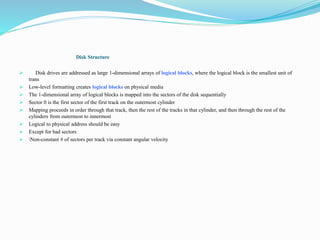
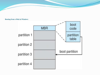
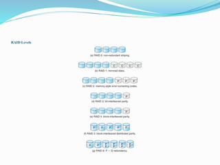
Presented by
K . Marisami(14BIT031)
: Mass-Storage Systems
 Overview of Mass Storage Structure
 Disk Structure
 Disk Attachment
 Disk Scheduling
 Disk Management
 Swap-Space Management
 RAID Structure
 Stable-Storage Implementation
Disk Structure
 Disk drives are addressed as large 1-dimensional arrays of logical blocks, where the logical block is the smallest unit of
trans
 Low-level formatting creates logical blocks on physical media
 The 1-dimensional array of logical blocks is mapped into the sectors of the disk sequentially
 Sector 0 is the first sector of the first track on the outermost cylinder
 Mapping proceeds in order through that track, then the rest of the tracks in that cylinder, and then through the rest of the
cylinders from outermost to innermost
 Logical to physical address should be easy
 Except for bad sectors
 Non-constant # of sectors per track via constant angular velocity
Objectives
 To describe the physical structure of secondary storage devices and its effects on the uses of the devices
 To explain the performance characteristics of mass-storage devices
 To evaluate disk scheduling algorithms
 To discuss operating-system services provided for mass storage, including RAID
Disk Attachment
 Host-attached storage accessed through I/O ports talking to I/O busses
 SCSI itself is a bus, up to 16 devices on one cable, SCSI initiator requests operation and SCSI targets perform tasks
 Each target can have up to 8 logical units (disks attached to device controller)
 FC is high-speed serial architecture
 Can be switched fabric with 24-bit address space – the basis of storage area networks (SANs) in which many hosts attach to
many storage units
 I/O directed to bus ID, device ID, logical unit
Disk Scheduling
 The operating system is responsible for using hardware efficiently — for the disk drives, this means having a fast access time
and disk bandwidth
 Minimize seek time
 Seek time  seek distance
 Disk bandwidth is the total number of bytes transferred, divided by the total time between the first request for service and the
completion of the last transfer
Selecting a Disk-Scheduling Algorithm
 SSTF is common and has a natural appeal
 SCAN and C-SCAN perform better for systems that place a heavy load on the disk
 Less starvation
 Performance depends on the number and types of requests
 Requests for disk service can be influenced by the file-allocation method
 And metadata layout
 The disk-scheduling algorithm should be written as a separate module of the operating system, allowing it to be replaced with
a different algorithm if necessary
 Either SSTF or LOOK is a reasonable choice for the default algorithm
Disk Management
 Low-level formatting, or physical formatting — Dividing a disk into sectors that the disk controller can read and write
 Each sector can hold header information, plus data, plus error correction code (ECC)
 Usually 512 bytes of data but can be selectable
 To use a disk to hold files, the operating system still needs to record its own data structures on the disk
 Partition the disk into one or more groups of cylinders, each treated as a logical disk
 Logical formatting or “making a file system”
 To increase efficiency most file systems group blocks into clusters
 Disk I/O done in blocks
 File I/O done in clusters
Booting from a Disk in Windows
Swap-Space Management
 Swap-space — Virtual memory uses disk space as an extension of main memory
 Less common now due to memory capacity increases
 Swap-space can be carved out of the normal file system, or, more commonly, it can be in a separate disk partition (raw)
 Swap-space management
 4.3BSD allocates swap space when process starts; holds text segment (the program) and data segment
 Kernel uses swap maps to track swap-space use
 Solaris 2 allocates swap space only when a dirty page is forced out of physical memory, not when the virtual memory page is
first created
 File data written to swap space until write to file system requested
 Other dirty pages go to swap space due to no other home
 Text segment pages thrown out and reread from the file system as needed
Data Structures for Swapping on Linux Systems
RAID Structure
 RAID – redundant array of inexpensive disks
 multiple disk drives provides reliability via redundancy
 Increases the mean time to failure
 Mean time to repair – exposure time when another failure could cause data loss
 Mean time to data loss based on above factors
 If mirrored disks fail independently, consider disk with 1300,000 mean time to failure and 10 hour mean time to repair
 Mean time to data loss is 100, 0002 / (2 ∗ 10) = 500 ∗ 106 hours, or 57,000 years!
 Frequently combined with NVRAM to improve write performance
 Several improvements in disk-use techniques involve the use of multiple disks working cooperatively
RAID Levels
Other Features
 Regardless of where RAID implemented, other useful features can be added
 Snapshot is a view of file system before a set of changes take place (i.e. at a point in time)
 More in Ch 12
 Replication is automatic duplication of writes between separate sites
 For redundancy and disaster recovery
 Can be synchronous or asynchronous
 Hot spare disk is unused, automatically used by RAID production if a disk fails to replace the failed disk and rebuild the RAID
set if possible
 Decreases mean time to repair
Stable-Storage Implementation
 Stable storage means data is never lost (due to failure, etc)
 To implement stable storage:
 Replicate information on more than one nonvolatile storage media with independent
failure modes
 Update information in a controlled manner to ensure that we can recover the stable
data after any failure during data transfer or recovery
 Disk write has 1 of 3 outcomes
1. Successful completion - The data were written correctly on disk
2. Partial failure - A failure occurred in the midst of transfer, so only some of the
sectors were written with the new data, and the sector being written during the
failure may have been corrupted
3. Total failure - The failure occurred before the disk write started, so the previous
data values on the disk remain intact
Stable-Storage Implementation
 If failure occurs during block write, recovery procedure restores block to consistent state
 System maintains 2 physical blocks per logical block and does the following:
1. Write to 1st physical
2. When successful, write to 2nd physical
3. Declare complete only after second write completes successfully
 Systems frequently use NVRAM as one physical to accelerate

 THANK YOU

Massstorage

  • 1.
    Presented by K .Marisami(14BIT031)
  • 2.
    : Mass-Storage Systems Overview of Mass Storage Structure  Disk Structure  Disk Attachment  Disk Scheduling  Disk Management  Swap-Space Management  RAID Structure  Stable-Storage Implementation
  • 3.
    Disk Structure  Diskdrives are addressed as large 1-dimensional arrays of logical blocks, where the logical block is the smallest unit of trans  Low-level formatting creates logical blocks on physical media  The 1-dimensional array of logical blocks is mapped into the sectors of the disk sequentially  Sector 0 is the first sector of the first track on the outermost cylinder  Mapping proceeds in order through that track, then the rest of the tracks in that cylinder, and then through the rest of the cylinders from outermost to innermost  Logical to physical address should be easy  Except for bad sectors  Non-constant # of sectors per track via constant angular velocity
  • 4.
    Objectives  To describethe physical structure of secondary storage devices and its effects on the uses of the devices  To explain the performance characteristics of mass-storage devices  To evaluate disk scheduling algorithms  To discuss operating-system services provided for mass storage, including RAID
  • 5.
    Disk Attachment  Host-attachedstorage accessed through I/O ports talking to I/O busses  SCSI itself is a bus, up to 16 devices on one cable, SCSI initiator requests operation and SCSI targets perform tasks  Each target can have up to 8 logical units (disks attached to device controller)  FC is high-speed serial architecture  Can be switched fabric with 24-bit address space – the basis of storage area networks (SANs) in which many hosts attach to many storage units  I/O directed to bus ID, device ID, logical unit
  • 6.
    Disk Scheduling  Theoperating system is responsible for using hardware efficiently — for the disk drives, this means having a fast access time and disk bandwidth  Minimize seek time  Seek time  seek distance  Disk bandwidth is the total number of bytes transferred, divided by the total time between the first request for service and the completion of the last transfer
  • 7.
    Selecting a Disk-SchedulingAlgorithm  SSTF is common and has a natural appeal  SCAN and C-SCAN perform better for systems that place a heavy load on the disk  Less starvation  Performance depends on the number and types of requests  Requests for disk service can be influenced by the file-allocation method  And metadata layout  The disk-scheduling algorithm should be written as a separate module of the operating system, allowing it to be replaced with a different algorithm if necessary  Either SSTF or LOOK is a reasonable choice for the default algorithm
  • 8.
    Disk Management  Low-levelformatting, or physical formatting — Dividing a disk into sectors that the disk controller can read and write  Each sector can hold header information, plus data, plus error correction code (ECC)  Usually 512 bytes of data but can be selectable  To use a disk to hold files, the operating system still needs to record its own data structures on the disk  Partition the disk into one or more groups of cylinders, each treated as a logical disk  Logical formatting or “making a file system”  To increase efficiency most file systems group blocks into clusters  Disk I/O done in blocks  File I/O done in clusters
  • 9.
    Booting from aDisk in Windows
  • 10.
    Swap-Space Management  Swap-space— Virtual memory uses disk space as an extension of main memory  Less common now due to memory capacity increases  Swap-space can be carved out of the normal file system, or, more commonly, it can be in a separate disk partition (raw)  Swap-space management  4.3BSD allocates swap space when process starts; holds text segment (the program) and data segment  Kernel uses swap maps to track swap-space use  Solaris 2 allocates swap space only when a dirty page is forced out of physical memory, not when the virtual memory page is first created  File data written to swap space until write to file system requested  Other dirty pages go to swap space due to no other home  Text segment pages thrown out and reread from the file system as needed
  • 11.
    Data Structures forSwapping on Linux Systems
  • 12.
    RAID Structure  RAID– redundant array of inexpensive disks  multiple disk drives provides reliability via redundancy  Increases the mean time to failure  Mean time to repair – exposure time when another failure could cause data loss  Mean time to data loss based on above factors  If mirrored disks fail independently, consider disk with 1300,000 mean time to failure and 10 hour mean time to repair  Mean time to data loss is 100, 0002 / (2 ∗ 10) = 500 ∗ 106 hours, or 57,000 years!  Frequently combined with NVRAM to improve write performance  Several improvements in disk-use techniques involve the use of multiple disks working cooperatively
  • 13.
  • 14.
    Other Features  Regardlessof where RAID implemented, other useful features can be added  Snapshot is a view of file system before a set of changes take place (i.e. at a point in time)  More in Ch 12  Replication is automatic duplication of writes between separate sites  For redundancy and disaster recovery  Can be synchronous or asynchronous  Hot spare disk is unused, automatically used by RAID production if a disk fails to replace the failed disk and rebuild the RAID set if possible  Decreases mean time to repair
  • 15.
    Stable-Storage Implementation  Stablestorage means data is never lost (due to failure, etc)  To implement stable storage:  Replicate information on more than one nonvolatile storage media with independent failure modes  Update information in a controlled manner to ensure that we can recover the stable data after any failure during data transfer or recovery  Disk write has 1 of 3 outcomes 1. Successful completion - The data were written correctly on disk 2. Partial failure - A failure occurred in the midst of transfer, so only some of the sectors were written with the new data, and the sector being written during the failure may have been corrupted 3. Total failure - The failure occurred before the disk write started, so the previous data values on the disk remain intact
  • 16.
    Stable-Storage Implementation  Iffailure occurs during block write, recovery procedure restores block to consistent state  System maintains 2 physical blocks per logical block and does the following: 1. Write to 1st physical 2. When successful, write to 2nd physical 3. Declare complete only after second write completes successfully  Systems frequently use NVRAM as one physical to accelerate
  • 17.