Downloaded 146 times


![CISPR vs. FCC
960-1000
Class A
0.5 1.6 5 30 88 216
0.15 - 0.5 0.5 - 30 30 - 88 88 - 216 216 - 960 >1000
0.45 – 1.6 1.6 - 30 30 - 88 88 - 216 216 - 1000 >1000
Class B
0.15 - 0.5 0.5 - 5 5 - 30 30 - 88 88 - 216 216 - 960 >1000
0.455 – 1.6 1.6 - 30 30 - 88 88 - 216 216 - 1000 >1000
f [MHz]
0.1 1 10 100 1000
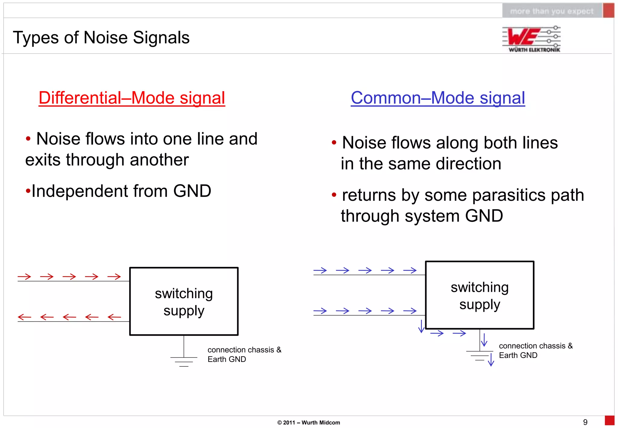
differential mode noise common mode noise
• Class A
commercial, industrial, business environment equipment
• Class B
residential environment equipment
f [MHz] CISPR 22 - conducted
f [MHz] FCC 15 - conducted
f [MHz] CISPR 22 - radiated
f [MHz] FCC 15 - radiated
© 2011 – Wurth Midcom 7](https://image.slidesharecdn.com/wrthelektronik-110913122819-phpapp02/75/Seminario-Wurth-Elektronik-7-2048.jpg)
![CISPR vs. FCC
960-1000
Class A
0.5 1.6 5 30 88 216
0.15 - 0.5 0.5 - 30 30 - 88 88 - 216 216 - 960 >1000
0.45 – 1.6 1.6 - 30 30 - 88 88 - 216 216 - 1000 >1000
Class B
0.15 - 0.5 0.5 - 5 5 - 30 30 - 88 88 - 216 216 - 960 >1000
0.455 – 1.6 1.6 - 30 30 - 88 88 - 216 216 - 1000 >1000
f [MHz]
0.1 1 10 100 1000
differential mode noise common mode noise
• Class A
commercial, industrial, business environment equipment
• Class B
residential environment equipment
f [MHz] CISPR 22 - conducted
f [MHz] FCC 15 - conducted
f [MHz] CISPR 22 - radiated
f [MHz] FCC 15 - radiated
© 2011 – Wurth Midcom 10](https://image.slidesharecdn.com/wrthelektronik-110913122819-phpapp02/75/Seminario-Wurth-Elektronik-10-2048.jpg)


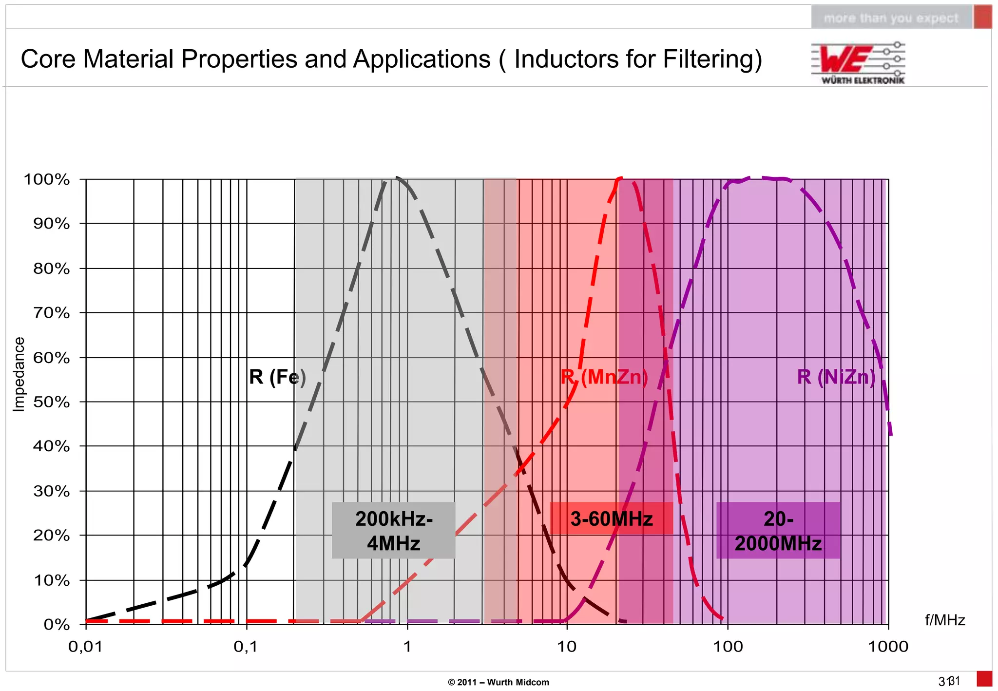


This document provides an introduction to concepts and techniques for electromagnetic interference (EMI) in switched mode power supplies (SMPS). It discusses EMI and electromagnetic compatibility (EMC) standards, types of noise signals, common noise countermeasures like shields and filters, magnetic field and flux basics, core materials and their properties, and common mode chokes. The focus is on helping designers understand and mitigate EMI in their power supply designs.


