Research Inventy : International Journal of Engineering and Science
1. RESEARCH INVENTY: International Journal of Engineering and Science
ISBN: 2319-6483, ISSN: 2278-4721, Vol. 2, Issue 1
(November 2012), PP 48-52
www.researchinventy.com
Variation of Impulsive Noise with Distance of the Noise Source
from the Power Line in Power Line Communication
Anirban Sengupta, Chitrangada Roy
1
Department of Electrical Engineering
Sharda University, Greater Noida, U.P, India
2
Associate System Engineer IBM, Kolkata, India
Abstract: - This paper describes the variation of impulsive noise with the distance of the noise source from the
power line in power line communication. Here a rectifier has been chosen as the periodic impulsive noise
source and an induction motor has been taken as aperiodic impulsive noise source. The distance of the noise
source from the power line has been varied and the variation of noise magnitude has been plotted, also the
variation has been modeled mathematically.
Keywords- power line communication, noise.
I Introduction
The idea of sending communication signal over the same power lines (which is mainly used to
distribute electrical power) is as old as telegraph itself. A channel characteristic of the power line shows a
typical behavior which is briefly described here. Impedance is highly varying with frequency and ranges from a
few Ohm to few kilo Ohm. At some frequencies there are peaks in the impedance characteristics. At these peaks
the network behaves like a parallel resonant circuit. However, in most of the frequency ranges the impedance
shows inductive or capacitive behavior. Characteristic impedance of a power line cable is typically in the range
of 90 Ohm. Net impedance is not only influenced by characteristic impedance but also by network topology and
connected loads which may have highly varying impedances as well.
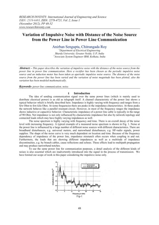
The noise spectrum is highly varying with frequency and time. There is an overall decay of the noise
level with increasing frequency. A typical example of a measured noise spectrum is shown in Fig. 1. Noise at
the power line is influenced by a large number of different noise sources with different characteristics. There are
broadband disturbances, e.g. universal motors, and narrowband disturbances, e.g. HF-radio signals, power
supplies. The shape of the noise curve is very much dependent on location and time. Because of the frequency
dependency of impedance of the power line, impedance mismatch often occurs when coupling in and out.
Furthermore, the loads that are showing different impedances as well as a multitude of impedance
discontinuities, e.g. by branch cables, cause reflections and echoes. These effects lead to multipath propagation
and may produce narrowband notches.
To use the same power line for communication purposes, a detail analysis of the different kinds of
noises is also essential which are inadvertently introduced into the signal in the process of transmission. We
have limited our scope of work in this paper considering the impulsive noise only.
Fig-1
48
2. Variation of Impulsive Noise with Distance of…
Next section describes all these different kinds of noises, their characteristic behavior and models.
Section 3 describes the proposed filters and their design considerations. Next, in section 4 results of simulation
are presented and finally the paper concludes in section 5.
II. Powerline Noises
Colored Background Noise- This type of noise is caused by overlaying of multiple sources of noise with
2
relatively low power. Generally, power density of background noise is between -120 dB (V /Hz) and -140 dB
2
(V /Hz) with an increasing power density towards lower frequencies (e.g. below 1 MHz) as in [1].
A typical measurement result of background noise with low power density is illustrated in Figure 2
below
Figure 2: Colour background noise pattern
Generally, we can see that power density of background noise decreases towards higher frequencies.
Results of multiple measurements of noise in [2] showed that decreasing power density with increasing
frequency can be approximated by an exponential decaying curve in logarithmic scale.
A(f)=A∞+A0+exp(-f/f0) (1)
Narrow Band Noise- In general, noise scenarios in power line channels contain narrow-band noise, whose
intensity and frequency varies over place and time. The main sources for narrow band noise are broadcasters in
long, middle and short wave range as well as several radio services like amateur radio, so that almost the whole
frequency range until 20 MHz is overlaid by narrow-band noise. A part of a noise spectrum with clearly visible
narrow-band noise is shown Figure 3 below as in [3].
Figure 3: Narrow-band noise pattern
We can see that power density is distinctly above background noise level. Thus, narrow-band noise has
to be considered separately when generating noises in a channel emulator. Obviously, narrow-band noise can be
modeled as a sum of multiple sine noises with different amplitudes.
Using a deterministic model the signal results in the following equation
N
nnarrowband (t ) Ai (t ).sin(2 fi t )
i 1 (2).
Impulsive Noise- Net-synchronous impulsive noise occurs in 50 Hz-alternating voltage current network with
frequencies of 50 Hz or 100 Hz. They are caused by synchronous power converters occurring in dimmers and by
all kinds of rectifiers using diodes [4].
49
3. Variation of Impulsive Noise with Distance of…
Figure .4: Periodic impulsive noise characteristics
With “aperiodic impulsive noise” we will describe this type of noise which occurs time-randomly. In
literature, this noise is also known as “asynchronous impulsive noise”. However, since periodic impulsive noise
is also asynchronous to supply frequency, we will choose the clearer term “aperiodic impulsive noise”.
This type of noise is caused by all kinds of switching operations, for example by household appliances,
electric motors, or condenser discharge lamps. Aperiodic impulsive noise very often occurs in bunches (so
called “burst noise”), which increases their disturbing impact. With many different sources this noise has very
different properties regarding time response and spectral properties. A typical example for such noise is given in
Figure 5.
Figure 5: Time characteristics and spectral behavior of Impulsive noise
III. Proposed Technique
a) Variation of periodic Impulsive Noise:- In this proposed technique we have taken a controlled
rectifier as the noise source and the distance of the noise source from the power line has been varied
and the result of this variation has been plotted. The proposed technique is shown in Figure 6.
Figure 6: Proposed technique to vary the distance of the periodic impulsive noise from power line
b) Variation of Aperiodic Impulsive Noise:- Apeiodic Impulsive Noise occurs due to different kinds of
switching operation, like electric motors. In this paper a three phase induction motor has been taken as
the noise source and the distance of the noise source from the power line has been varied and the effect
of the variation has been plotted. The proposed scheme is shown in Figure 7.
50
4. Variation of Impulsive Noise with Distance of…
Figure 7:- Proposed technique to vary distance of the aperiodic impulsive noise source
IV. Results And Discussions
a) Variation of periodic Impulsive Noise:- The proposed technique is modeled using MATLAB Simulink
which is essentially a controlled rectifier set situated at a distance from the power line. The distance of
the noise source from the power line has been varied gradually and the effect of this variation has been
recorded and a mathematical formula has been derived. The experimented values and the mathematical
values of this variation are shown in Figure 8 and Figure 9 respectively.
Figure 8: Experimental variation of periodic impulsive noise magnitude with distance
2500
2000
1500
Noise magnitude
1000
500
0
0 20 40 60 80 100 120 140 160
Distance
Figure 9: Generalized variation of periodic impulsive noise magnitude with distance
From this figure it can be concluded that the noise magnitude decreases exponentially with the distance of the
noise source from the communication channel. Which can be expressed by the formula given below:-
P(d)=A0e(-0.0015d) (3)
Where, P(d)= Noise power at a distance d
A0= Noise magnitude when d=0
b) Variation of Aperiodic Impulsive Noise:- The variation of the distance of the induction motor with the
power line is shown in Figure 10.
51
5. Variation of Impulsive Noise with Distance of…
Figure 10: Variation of Aperiodic Impulsive noise with distance
This variation is almost like a straight line. Therefore, it can be concluded that aperiodic impulsive
noise varies almost linearly with the distance of the noise
source from the power line. This variation can be modeled mathematically as:-
P(d)=P(0)-d (4)
Where P(d)= Noise magnitude
P(0)= Noise magnitude at d=0
d= Distance of the noise Source from the power line
Based on equation (4), a generalized variation of the noise power with the variation of the noise source
from the power line can be drawn as shown in Figure (11)
Figure 10: Generalized variation of aperiodic impulsive noise with distance
V. Conclusion
The main objective of this paper is to study and understand the variation of the noise magnitude with
the variation of the distance of the power line from the noise source. Here a controlled rectifier and an induction
motor are taken as the noise sources and the distance of the noise sources from the power line has been varied.
Based on this variation a mathematical modeling formula has been generated to understand the variation and to
model the variation for further use.
References:-
[1] Yong-tao Ma, Kai-hua Liu, Zhi-jun Zhang, Jie-xiao Yu, Xiao-lin Gong, “ Modeling the Colored Background Noise of Power Line
Communication Channel Based on Artificial Neural Network.”IEEE Trans on Consumer Electronics, 2007, 45(2): 345~348
[2] H. Phillipps, “Modeling of powerline communication channels”,proc .3rd Int.symp.power line Communications and its applications,
Lancaster, U.K., 1999,pp.14-21.
[3] M. Zimmermann and K. Dostert, “Analysis and modeling of impulsive noise in broad-band power-line communications,” IEEE
transactions on ELECTROMAGNETIC COMPATIBILITY, Vol.44, pp.249-258, FEB 2002
[4] OPERA, “ Theoretical Postulation of PLC Channel Model”, version: 2 .
52
![Variation of Impulsive Noise with Distance of…
Next section describes all these different kinds of noises, their characteristic behavior and models.
Section 3 describes the proposed filters and their design considerations. Next, in section 4 results of simulation
are presented and finally the paper concludes in section 5.
II. Powerline Noises
Colored Background Noise- This type of noise is caused by overlaying of multiple sources of noise with
2
relatively low power. Generally, power density of background noise is between -120 dB (V /Hz) and -140 dB
2
(V /Hz) with an increasing power density towards lower frequencies (e.g. below 1 MHz) as in [1].
A typical measurement result of background noise with low power density is illustrated in Figure 2
below
Figure 2: Colour background noise pattern
Generally, we can see that power density of background noise decreases towards higher frequencies.
Results of multiple measurements of noise in [2] showed that decreasing power density with increasing
frequency can be approximated by an exponential decaying curve in logarithmic scale.
A(f)=A∞+A0+exp(-f/f0) (1)
Narrow Band Noise- In general, noise scenarios in power line channels contain narrow-band noise, whose
intensity and frequency varies over place and time. The main sources for narrow band noise are broadcasters in
long, middle and short wave range as well as several radio services like amateur radio, so that almost the whole
frequency range until 20 MHz is overlaid by narrow-band noise. A part of a noise spectrum with clearly visible
narrow-band noise is shown Figure 3 below as in [3].
Figure 3: Narrow-band noise pattern
We can see that power density is distinctly above background noise level. Thus, narrow-band noise has
to be considered separately when generating noises in a channel emulator. Obviously, narrow-band noise can be
modeled as a sum of multiple sine noises with different amplitudes.
Using a deterministic model the signal results in the following equation
N
nnarrowband (t ) Ai (t ).sin(2 fi t )
i 1 (2).
Impulsive Noise- Net-synchronous impulsive noise occurs in 50 Hz-alternating voltage current network with
frequencies of 50 Hz or 100 Hz. They are caused by synchronous power converters occurring in dimmers and by
all kinds of rectifiers using diodes [4].
49](data:image/gif;base64,R0lGODlhAQABAIAAAAAAAP///yH5BAEAAAAALAAAAAABAAEAAAIBRAA7)