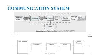
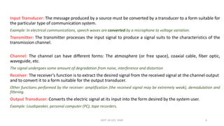
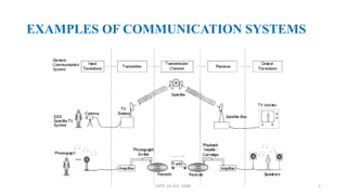
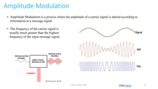
COMMUNICATION SYSTEMS
Presented by:
Vijnan Institute Of Science & Technology,Elanji
ECE Dept.
COMMUNICATION
Communication is the transfer of information from one place to
another.
This should be done
- as efficiently as possible
- with as much fidelity/reliability as possible
- as securely as possible
Communication System: Components/subsystems act together to
accomplish information transfer/exchange.
DEPT. OF ECE, VISAT 2
COMMUNICATION SYSTEM
Output
message
Input message
Input Transducer
Transmitter Channel Receiver
Output
Transducer
DEPT. OF ECE, VISAT 3
Input Transducer: The message produced by a source must be converted by a transducer to a form suitable for
the particular type of communication system.
Example: In electrical communications, speech waves are converted by a microphone to voltage variation.
Transmitter: The transmitter processes the input signal to produce a signal suits to the characteristics of the
transmission channel.
Channel: The channel can have different forms: The atmosphere (or free space), coaxial cable, fiber optic,
waveguide, etc.
The signal undergoes some amount of degradation from noise, interference and distortion
Receiver: The receiver’s function is to extract the desired signal from the received signal at the channel output
and to convert it to a form suitable for the output transducer.
Other functions performed by the receiver: amplification (the received signal may be extremely weak), demodulation and
filtering.
Output Transducer: Converts the electric signal at its input into the form desired by the system user.
Example: Loudspeaker, personal computer (PC), tape recorders.
DEPT. OF ECE, VISAT 4
EXAMPLES OF COMMUNICATION SYSTEMS
DEPT. OF ECE, VISAT 5
BASIC MODES OF COMMUNICATION
1) point – to – point communication
• Communication takes place over a
link between a single transmitter
and a receiver.
Ex: Telephony
2) Broadcast mode
• There are a large number of receivers corresponding to a single
transmitter.
Ex: Radio and television.
Click HereDEPT. OF ECE, VISAT 6
Basic Terminologies in Communication
i. Signal
• Information converted in electrical form and suitable for transmission is called a signal.
• Signals can be either analog or digital.
ii. Transmitter
A transmitter processes the incoming message signal so as to make it suitable for
transmission through a channel and subsequent reception.
iii. Transducer
Any device that converts one form of energy into another
Electrical transducer : a device which converts some physical variable (Pressure,
displacement, temperature, force, etc.) into corresponding variations in the electrical signal
at its output.
iv. Attenuation
The loss of strength of a signal while propagating through a medium is known as
attenuation. DEPT. OF ECE, VISAT 7
v. Amplification
Amplification is the process of increasing the amplitude (and also strength)
vi. Noise
Noise is random, undesirable (unwanted) electric energy that enters the communication system
vii. Receiver
A receiver extracts the desired message signals from the received signals at the channel output. It
consists of a pickup antenna to pick up signal, demodulator, an amplifier and the transducer.
viii. Range
The maximum (largest) distance between a source and a destination up to which the signal is
received with sufficient strength is termed as range.
ix. Bandwidth
The frequency range over which equipment operates or the portion of the spectrum occupied
by the signal is referred as bandwidth.
x. Modulation
The process of superimposing a low frequency signal on a high frequency wave, which acts
as a carrier wave for long distance transmission is known as modulation.
xi. Demodulation
The process of regaining (retrieval) of information from carrier wave at the receiver is
termed as demodulation. (This is the reverse process of modulation).DEPT. OF ECE, VISAT 8
• Different frequency bands
Extremely Low Frequency (ELF) 30 Hz to 300 Hz,
Voice Frequency (VF) - 300 Hz to 3000 Hz
Very Low Frequency (VLF) 3 kHz to 30 kHZ
Low Frequency (LF) 30 kHz to 300 kHz
Medium Frequency (MF) 300 kHz to 3000 kHz
High Frequency (HF)0 3 MHz to 30 MHz
Very High Frequency (VHF) 30 MHz to 300 MHz
Ultra High Frequency (UHF) 300 MHz to 3000 MHz
Super High Frequency (SHF) 3 GHz to 30 GHz
(80 to 108 MHz)
DEPT. OF ECE, VISAT 9
Some important wireless communication frequency bands
DEPT. OF ECE, VISAT 10
Radio Wave Propagation Modes
1 Ground Wave Propagation
Follows contour of the earth - Can Propagate considerable distances
Frequencies up to 2 MHz Example : AM radio
DEPT. OF ECE, VISAT 11
2 Sky Wave Propagation
Signal reflected from ionized layer
of atmosphere. Signal can travel
a number of hops, back and forth
Examples SW radio
3 Line-of-Sight Propagation
Transmitting and receiving antennas
must be within line of sight
example
Satellite communication
Ground communication
DEPT. OF ECE, VISAT 12
DEPT. OF ECE, VISAT 13
DEPT. OF ECE, VISAT 14
NEED FOR MODULATION
1. Size of the Antenna or aerial
For efficient radiation and reception, the transmitting antennas
would have lengths comparable to the wavelength used.
 
    

8
3
3 10
20 km 5 km
415 10
A vertical antenna of this size is impracticable and hence direct
transmission of such base band signals is not practical.
DEPT. OF ECE, VISAT 15
2. Effective Power Radiated By An Antenna
• According to theoretical study of radiation from a linear antenna of length
‘ℓ’, the power radiated is proportional to wavelength λ.
• Thus for the same antenna length, the power radiated increases with
decreasing λ (i.e increasing frequency).
• Hence effective power radiated by a long wavelength base band signal
would be small.
• For a good transmission, we need high power and hence we will use high
frequency transmission.
NEED FOR MODULATION
DEPT. OF ECE, VISAT 16
3. Mixing up of signals different transmitters
Sound range:- from 20 Hz to 20 kHz.
• So all signals from the different sources would be hopelessly and inseparably
mixed up.
• In order to separate the various signals, it is necessary to convert them all to
different portions of electromagnetic spectrum.
• Each must be given its own frequency location.
• This also overcomes the difficulties of power radiation at low frequencies
and reduces interference.
NEED FOR MODULATION
MODULATION AND ITS NECESSITY.mp4
DEPT. OF ECE, VISAT 17
• Signals to be transmitted are superimposed on high frequency (small
wavelength) waves called carrier waves. This process is termed as
modulation, which attaches information to it.
• The information is then transmitted by radiating these modified carrier
waves called modulated waves.
• The modified carrier waves called modulated waves.
• The carrier wave may be continuous (sinusoidal) or in the form of pulses.
MODULATION
DEPT. OF ECE, VISAT 18
DEPT. OF ECE, VISAT 19
MODULATION
• A sinusoidal carrier wave can be represented as
• c(t) = Ac sin (wc t+Ф) where c (t) is the signal strength (voltage or
current), Ac is the amplitude, ωc=2πfc is the angular frequency and Ф is the
initial phase of carrier wave.
• During the process of modulation, any of three parameters viz. Ac, ωc and Ф
of the carrier wave can be controlled by the message or information signal.
DEPT. OF ECE, VISAT 20
DEPT. OF ECE, VISAT 21
Amplitude Modulation
• Amplitude Modulation is a process where the amplitude of a carrier signal is altered according to
information in a message signal.
• The frequency of the carrier signal is
usually much greater than the highest
frequency of the input message signal.
Click HereDEPT. OF ECE, VISAT 22
1. Carrier signal equations
The carrier can be described in terms of a sine wave as follows:
c(t) = Ac sin (ωc t + φ)
Where:
carrier frequency in Hertz is equal to ωc / 2 π
Ac is the carrier amplitude
φ is the initial phase of carrier wave.
Both Ac and φ can be omitted to simplify the equation by changing Ac to "1" and φ to "0".
2. Modulating signal equations:
m (t) = Am sin (ωm t + φ)
Where:
modulating signal frequency in Hertz is equal to ωm / 2 π
Am is the carrier amplitude
Both Am and φ can be omitted to simplify the equation by changing Am to "1" and φ to "0".
DEPT. OF ECE, VISAT 23
3. Overall modulated signal
The equation for the overall modulated signal is obtained by multiplying the carrier and the modulating signal
together. Substituting in the individual relationships for the carrier and modulating signal, the overall signal
becomes:
Where is the modulation index. In practice, μ is kept ≤ 1 to avoid distortion.
Using the trigonometric relation sinA sinB = ½ (cos(A – B) – cos (A + B), we can write cm (t) as
DEPT. OF ECE, VISAT 24
Here ωc – ωm and ωc + ωm are respectively called the lower side and upper side frequencies. The
modulated signal now consists of the carrier wave of frequency ωc plus two sinusoidal waves each with a
frequency slightly different from, known as side bands.
DEPT. OF ECE, VISAT 25
Detection AM wave
Click Here
DEPT. OF ECE, VISAT 26
OVERVIEW OF AM
Modulator Demodulator
Baseband Signal
with frequency
fm
(Modulating Signal)
Bandpass Signal
with frequency
fc
(Modulated Signal)
Channel
Original Signal
with frequency
fm
Source Sink
fc >> fm
DEPT. OF ECE, VISAT 27
Common AM Applications
i. AM-radio Broadcasting
ii. TV picture (video)
iii. Two way radio
• a. air-craft b. Amateur radio(SSB)
• c. Citizen’s band radio d. Military
DEPT. OF ECE, VISAT 28
Drawbacks in AM
1. Low efficiency – only 20 to 30% is useful.
2. Noisy reception – AM signal is easily affected by external
atmosphere and electrical disturbances.
3. Operating range is small.
4. Quality: The allowed AM bandwidth is only 10kHz and for
transmission of all audio frequencies about 30 kHz bandwidth is
required which affects fidelity. Due to limited bandwidth stereotype
transmission is not possible
DEPT. OF ECE, VISAT 29
THANK YOU
DEPT. OF ECE, VISAT 30

Physics Class 12 Communication Powerpoint presentation

  • 1.
    COMMUNICATION SYSTEMS Presented by: VijnanInstitute Of Science & Technology,Elanji ECE Dept.
  • 2.
    COMMUNICATION Communication is thetransfer of information from one place to another. This should be done - as efficiently as possible - with as much fidelity/reliability as possible - as securely as possible Communication System: Components/subsystems act together to accomplish information transfer/exchange. DEPT. OF ECE, VISAT 2
  • 3.
    COMMUNICATION SYSTEM Output message Input message InputTransducer Transmitter Channel Receiver Output Transducer DEPT. OF ECE, VISAT 3
  • 4.
    Input Transducer: Themessage produced by a source must be converted by a transducer to a form suitable for the particular type of communication system. Example: In electrical communications, speech waves are converted by a microphone to voltage variation. Transmitter: The transmitter processes the input signal to produce a signal suits to the characteristics of the transmission channel. Channel: The channel can have different forms: The atmosphere (or free space), coaxial cable, fiber optic, waveguide, etc. The signal undergoes some amount of degradation from noise, interference and distortion Receiver: The receiver’s function is to extract the desired signal from the received signal at the channel output and to convert it to a form suitable for the output transducer. Other functions performed by the receiver: amplification (the received signal may be extremely weak), demodulation and filtering. Output Transducer: Converts the electric signal at its input into the form desired by the system user. Example: Loudspeaker, personal computer (PC), tape recorders. DEPT. OF ECE, VISAT 4
  • 5.
    EXAMPLES OF COMMUNICATIONSYSTEMS DEPT. OF ECE, VISAT 5
  • 6.
    BASIC MODES OFCOMMUNICATION 1) point – to – point communication • Communication takes place over a link between a single transmitter and a receiver. Ex: Telephony 2) Broadcast mode • There are a large number of receivers corresponding to a single transmitter. Ex: Radio and television. Click HereDEPT. OF ECE, VISAT 6
  • 7.
    Basic Terminologies inCommunication i. Signal • Information converted in electrical form and suitable for transmission is called a signal. • Signals can be either analog or digital. ii. Transmitter A transmitter processes the incoming message signal so as to make it suitable for transmission through a channel and subsequent reception. iii. Transducer Any device that converts one form of energy into another Electrical transducer : a device which converts some physical variable (Pressure, displacement, temperature, force, etc.) into corresponding variations in the electrical signal at its output. iv. Attenuation The loss of strength of a signal while propagating through a medium is known as attenuation. DEPT. OF ECE, VISAT 7
  • 8.
    v. Amplification Amplification isthe process of increasing the amplitude (and also strength) vi. Noise Noise is random, undesirable (unwanted) electric energy that enters the communication system vii. Receiver A receiver extracts the desired message signals from the received signals at the channel output. It consists of a pickup antenna to pick up signal, demodulator, an amplifier and the transducer. viii. Range The maximum (largest) distance between a source and a destination up to which the signal is received with sufficient strength is termed as range. ix. Bandwidth The frequency range over which equipment operates or the portion of the spectrum occupied by the signal is referred as bandwidth. x. Modulation The process of superimposing a low frequency signal on a high frequency wave, which acts as a carrier wave for long distance transmission is known as modulation. xi. Demodulation The process of regaining (retrieval) of information from carrier wave at the receiver is termed as demodulation. (This is the reverse process of modulation).DEPT. OF ECE, VISAT 8
  • 9.
    • Different frequencybands Extremely Low Frequency (ELF) 30 Hz to 300 Hz, Voice Frequency (VF) - 300 Hz to 3000 Hz Very Low Frequency (VLF) 3 kHz to 30 kHZ Low Frequency (LF) 30 kHz to 300 kHz Medium Frequency (MF) 300 kHz to 3000 kHz High Frequency (HF)0 3 MHz to 30 MHz Very High Frequency (VHF) 30 MHz to 300 MHz Ultra High Frequency (UHF) 300 MHz to 3000 MHz Super High Frequency (SHF) 3 GHz to 30 GHz (80 to 108 MHz) DEPT. OF ECE, VISAT 9
  • 10.
    Some important wirelesscommunication frequency bands DEPT. OF ECE, VISAT 10
  • 11.
    Radio Wave PropagationModes 1 Ground Wave Propagation Follows contour of the earth - Can Propagate considerable distances Frequencies up to 2 MHz Example : AM radio DEPT. OF ECE, VISAT 11
  • 12.
    2 Sky WavePropagation Signal reflected from ionized layer of atmosphere. Signal can travel a number of hops, back and forth Examples SW radio 3 Line-of-Sight Propagation Transmitting and receiving antennas must be within line of sight example Satellite communication Ground communication DEPT. OF ECE, VISAT 12
  • 13.
    DEPT. OF ECE,VISAT 13
  • 14.
    DEPT. OF ECE,VISAT 14
  • 15.
    NEED FOR MODULATION 1.Size of the Antenna or aerial For efficient radiation and reception, the transmitting antennas would have lengths comparable to the wavelength used.         8 3 3 10 20 km 5 km 415 10 A vertical antenna of this size is impracticable and hence direct transmission of such base band signals is not practical. DEPT. OF ECE, VISAT 15
  • 16.
    2. Effective PowerRadiated By An Antenna • According to theoretical study of radiation from a linear antenna of length ‘ℓ’, the power radiated is proportional to wavelength λ. • Thus for the same antenna length, the power radiated increases with decreasing λ (i.e increasing frequency). • Hence effective power radiated by a long wavelength base band signal would be small. • For a good transmission, we need high power and hence we will use high frequency transmission. NEED FOR MODULATION DEPT. OF ECE, VISAT 16
  • 17.
    3. Mixing upof signals different transmitters Sound range:- from 20 Hz to 20 kHz. • So all signals from the different sources would be hopelessly and inseparably mixed up. • In order to separate the various signals, it is necessary to convert them all to different portions of electromagnetic spectrum. • Each must be given its own frequency location. • This also overcomes the difficulties of power radiation at low frequencies and reduces interference. NEED FOR MODULATION MODULATION AND ITS NECESSITY.mp4 DEPT. OF ECE, VISAT 17
  • 18.
    • Signals tobe transmitted are superimposed on high frequency (small wavelength) waves called carrier waves. This process is termed as modulation, which attaches information to it. • The information is then transmitted by radiating these modified carrier waves called modulated waves. • The modified carrier waves called modulated waves. • The carrier wave may be continuous (sinusoidal) or in the form of pulses. MODULATION DEPT. OF ECE, VISAT 18
  • 19.
    DEPT. OF ECE,VISAT 19
  • 20.
    MODULATION • A sinusoidalcarrier wave can be represented as • c(t) = Ac sin (wc t+Ф) where c (t) is the signal strength (voltage or current), Ac is the amplitude, ωc=2πfc is the angular frequency and Ф is the initial phase of carrier wave. • During the process of modulation, any of three parameters viz. Ac, ωc and Ф of the carrier wave can be controlled by the message or information signal. DEPT. OF ECE, VISAT 20
  • 21.
    DEPT. OF ECE,VISAT 21
  • 22.
    Amplitude Modulation • AmplitudeModulation is a process where the amplitude of a carrier signal is altered according to information in a message signal. • The frequency of the carrier signal is usually much greater than the highest frequency of the input message signal. Click HereDEPT. OF ECE, VISAT 22
  • 23.
    1. Carrier signalequations The carrier can be described in terms of a sine wave as follows: c(t) = Ac sin (ωc t + φ) Where: carrier frequency in Hertz is equal to ωc / 2 π Ac is the carrier amplitude φ is the initial phase of carrier wave. Both Ac and φ can be omitted to simplify the equation by changing Ac to "1" and φ to "0". 2. Modulating signal equations: m (t) = Am sin (ωm t + φ) Where: modulating signal frequency in Hertz is equal to ωm / 2 π Am is the carrier amplitude Both Am and φ can be omitted to simplify the equation by changing Am to "1" and φ to "0". DEPT. OF ECE, VISAT 23
  • 24.
    3. Overall modulatedsignal The equation for the overall modulated signal is obtained by multiplying the carrier and the modulating signal together. Substituting in the individual relationships for the carrier and modulating signal, the overall signal becomes: Where is the modulation index. In practice, μ is kept ≤ 1 to avoid distortion. Using the trigonometric relation sinA sinB = ½ (cos(A – B) – cos (A + B), we can write cm (t) as DEPT. OF ECE, VISAT 24
  • 25.
    Here ωc –ωm and ωc + ωm are respectively called the lower side and upper side frequencies. The modulated signal now consists of the carrier wave of frequency ωc plus two sinusoidal waves each with a frequency slightly different from, known as side bands. DEPT. OF ECE, VISAT 25
  • 26.
    Detection AM wave ClickHere DEPT. OF ECE, VISAT 26
  • 27.
    OVERVIEW OF AM ModulatorDemodulator Baseband Signal with frequency fm (Modulating Signal) Bandpass Signal with frequency fc (Modulated Signal) Channel Original Signal with frequency fm Source Sink fc >> fm DEPT. OF ECE, VISAT 27
  • 28.
    Common AM Applications i.AM-radio Broadcasting ii. TV picture (video) iii. Two way radio • a. air-craft b. Amateur radio(SSB) • c. Citizen’s band radio d. Military DEPT. OF ECE, VISAT 28
  • 29.
    Drawbacks in AM 1.Low efficiency – only 20 to 30% is useful. 2. Noisy reception – AM signal is easily affected by external atmosphere and electrical disturbances. 3. Operating range is small. 4. Quality: The allowed AM bandwidth is only 10kHz and for transmission of all audio frequencies about 30 kHz bandwidth is required which affects fidelity. Due to limited bandwidth stereotype transmission is not possible DEPT. OF ECE, VISAT 29
  • 30.
    THANK YOU DEPT. OFECE, VISAT 30