Download as PDF, PPTX


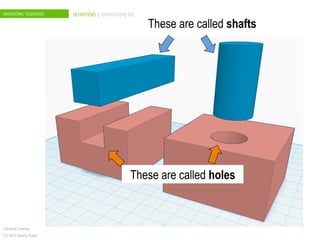
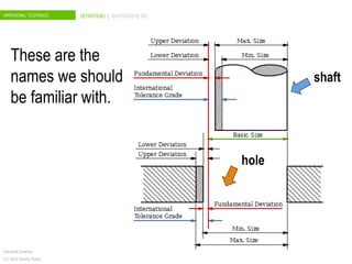
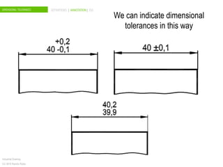

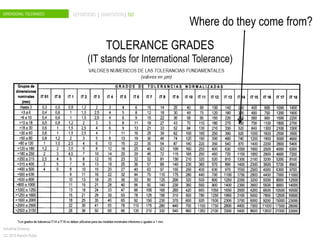

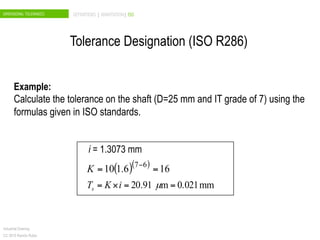
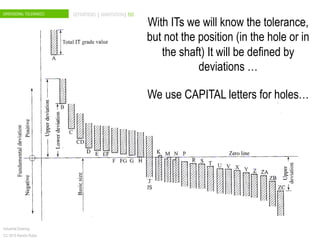
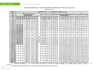
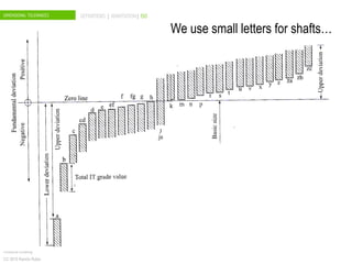
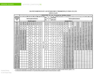
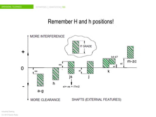
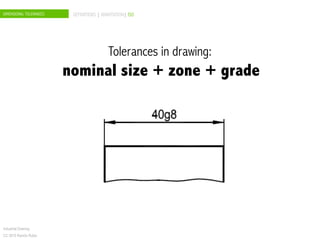
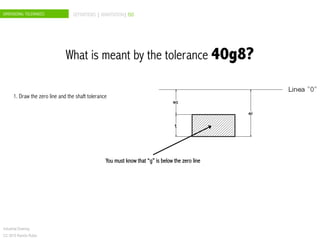

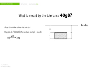
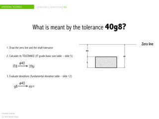
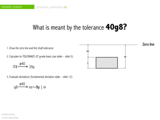
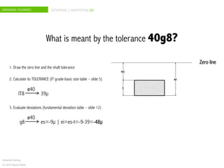
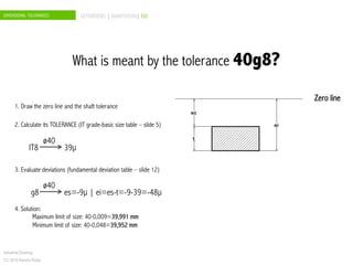
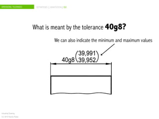


The document discusses dimensional tolerances in engineering drawings. It defines tolerances for shafts and holes using international tolerance (IT) grades. Lowercase letters indicate tolerances for shafts, while uppercase letters are used for holes. The document provides an example of calculating the tolerance for a 40mm shaft with an IT8 grade tolerance, showing the tolerance is 39μ, with a g8 deviation meaning the minimum size is 39.952mm. Dimensional tolerances are important for specifying permissible variation in manufactured component sizes.


