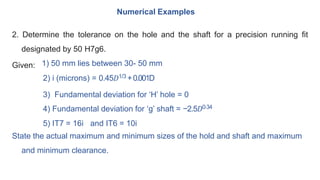
Okay, here are the steps to solve this problem:
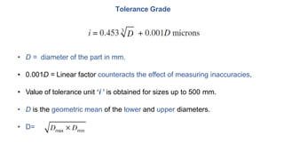
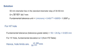
1) D = Geometric mean of lower and upper limit = √30 x 50 = 38.27 mm
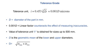
2) i = 0.45 x 38.271/3 + 0.001 x 38.27 = 1.307 μm
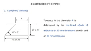
3) For H7 hole:
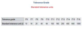
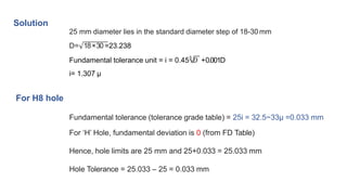
Tolerance grade (IT7) = 25i = 32.5 μm = 0.0325 mm
4) Fundamental deviation for H hole = 0
So, hole limits are: 50 mm and 50 + 0.0325 = 50.0325 mm
Hole tolerance = 0.0325 mm
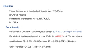
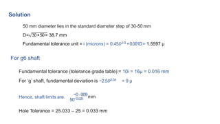
5) For g6 shaft:
Tolerance grade (IT