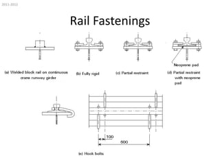
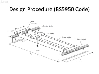
This document discusses the design of crane runway girders. It covers three main issues with crane girder and structure connections: vertical load transformation, free rotation at supports, and transverse load transformation. It then provides details on typical crane girder sections and rail fastenings. The design procedure outlined involves calculating vertical and horizontal loads, determining load combinations, and checking the girder for major axis bending capacity, lateral-torsional buckling, combined bending moments, web shear, local compression under wheels, web bearing and buckling, and deflections. References are made throughout to relevant British standards for structural steel design.

![2011-2012
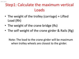
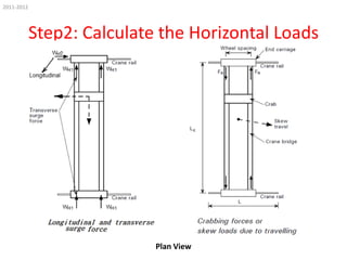
Step2: Calculate the Horizontal Loads
• Inertia forces produced by the motion drives
or brakes. Referred to as the surge load.
(clause 3.1.5.1 of BS 2573-1:1983[4]).
• Skew loads due to travelling referred to as the
crabbing force. (clause 3.1.5.2, BS 2573: Part
1:1983 [4])](https://image.slidesharecdn.com/crane-131210103424-phpapp01/85/Crane-16-320.jpg)


![Perancangan pesawat angkat & angkut [autosaved]](https://cdn.slidesharecdn.com/ss_thumbnails/perancanganpesawatangkatangkutautosaved-150823062211-lva1-app6891-thumbnail.jpg?width=640&height=640&fit=bounds)


