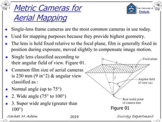
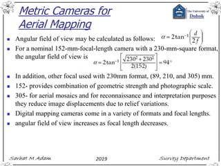
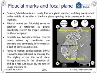
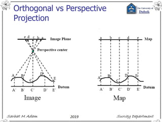
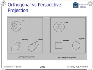
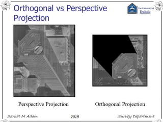
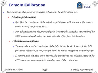
© 2019 Dr. Sarhat M Adam
BSc in civil Engineering
Msc in Geodetic Surveying
PhD in Engineering Surveying & Space Geodesy
Note – Figures and materials in the slides may be the authors own work or
extracted from internet websites, Materials by Duhok or Nottingham
universities staff and their slides, author's own knowledge, or various internet
image sources and books.
Lecture 3: Cameras &
their Geometry
Metric Cameras for
Aerial Mapping
◼ Single-lens frame cameras are the most common cameras in use today.
◼ Used for mapping purposes because they provide highest geometry.
◼ The lens is held fixed relative to the focal plane, film is generally fixed in
position during exposure, moved slightly to compensate image motion.
◼ Single lens classified according to
their angular field of view. Figure 01.
◼ Common film size of aerial cameras
is 230 mm (9 in^2) & angular view
classified as :
◼ Normal angle (up to 75°)
◼ 2. Wide angle (75° to 100°)
◼ 3. Super wide angle (greater than
100°) Figure 01
Metric Cameras for
Aerial Mapping
◼ Angular field of view may be calculated as follows:
◼ For a nominal 152-mm-focal-length camera with a 230-mm-square format,
the angular field of view is
◼ In addition, other focal used with 230mm format, (89, 210, and 305) mm.
◼ 152- provides combination of geometric strength and photographic scale.
◼ 305- for aerial mosaics and for reconnaissance and interpretation purposes
they reduce image displacements due to relief variations.
◼ Digital mapping cameras come in a variety of formats and focal lengths.
◼ angular field of view increases as focal length decreases.
Fiducial marks and focal plane
◼ Camera fiducial marks are usually four or eight in number, and they are situated
in the middle of the sides of the focal plane opening, in its corners, or in both
locations.
◼ Fiducial marks (or fiducials) serve to
establish a reference xy photo
coordinate system for image locations
on the photograph.
◼ fiducials are two-dimensional control
points whose xy coordinates are
precisely and accurately determined as
a part of camera calibration.
◼ Forward-motion compensation (FMC)
is usually accomplished by moving the
film slightly across the focal plane
during exposure, in the direction of,
and at a rate just equal to, the rate of
image movement.
FMC example
◼ An aerial camera with FMC and a 152.4-mm f is carried in an airplane traveling
at 200 (km/h). If the flying height above the terrain is 3500 m and if the exposure
time is 1/500 s, what distance (in mm) must the film be moved across the focal
plane during exposure in order to obtain a clear image?
Shutters
◼ Camera in aircraft is typically moving at a rapid speed.
◼ images will move across the focal plane during exposure.
◼ If exposure times are long or flying heights low, blurred images may result.
◼ Shutter has to open for very
short duration.
◼ For aircraft camera, shutter
is between 1/100 – 1/1000 s.
◼ 2 types in of shutter in
aircraft: between the lens
and focal plane shutters.
◼ Common types of between-
the-lens shutters are:
◼ leaf type, blade type, and
rotating-disk type.
Shutters
Camera mounts
◼ Mechanism used to attach the camera to the aircraft.
◼ The purpose is to ensure that the optical axis is vertical and the format is squarely
aligned with the direction of travel.
◼ Equipped with dampener to reduce or prevent vibrations & mechanism to allow
rotation in azimuth to correct for crab.
◼ Crab is a disparity in the orientation of the camera in the aircraft with respect to
the aircraft’s actual travel direction.
◼ Crab has the undesirable effect of reducing the stereoscopic ground coverage, fig.
◼ Some mounts like Leica PAV 80 provide gyro stabilization for the camera.
◼ Control is provided in three directions: rotation about the longitudinal axis (roll),
rotation about the transverse axis (pitch), and rotation about the optical axis (yaw
or drift).
Camera Control
◼ Intervalometer to automatically trips and control the shutter.
◼ Early at fixed interval of time which depends on focal, format size, end lap, h
above ground, and aircraft velocity.
◼ Had disadvantage when variation in terrain elevation, flying height, or aircraft
velocities occur.
◼ More advanced Intervalometer includes GPS enabling the exposures to be made
at preprogramed locations.
◼ Exposure control is another control device that measures terrain brightness and
correlates it with the optimum combination of aperture size & shutter speed.
◼ Modern camera controls consist of GPS and inertial navigation devices that
resulting in reduced human error.
Digital Mapping Cameras
◼ Digital frame camera
◼ It consists of a two-dimensional array of CCD elements, called a full-frame sensor.
◼ Ex, Teledyne DALSA has CCD elements approximately 14,600 × 17,200 (250
million) pixels. Has a 5.6 μm pixel size and thus can capture an 82 × 99 mm image
in the focal plane of a camera
◼ Linear array sensors
◼ Geometric characteristics of a linear array sensor are different from 2-D CCDs.
◼ Acquires an image by sweeping a line of detectors across the terrain.
◼ One-dimensional array or strip of CCD elements mounted in the focal plane.
◼ Turbulence will cause the resulting image to be distorted due to pitching and rolling.
◼ GPS/INS system help to measure the position and angular attitude of the sensor.
◼ Multiple linear arrays forward, down, and backward to get required stereo view.
Linear array sensors
Rectified with GPS/INS
Raw image without rectification
Camera classification
Leica RD30
iXA
Carl Zeiss film
F.8 Mk II aerial camera, 1943
iXA
Camera classification
Ultra CAM Eagle M2
Task: Find the high flight of each of the camera listed in the figures if you maintain
the same foot print of (1,749*2,301) m of along and across track respectively. You
may wish to visit the Vexel Imaging website for more information to help you
solving this problem.
F 80 F 100 F 120 F 210
Aerial Photogrammetry
◼ Using large format professional cameras such as Ultra_CAM-D from Microsoft.
◼ From UAV small format cameras
So what is different between
professional aerial photographs and
via UAVs?
Aerial Photogrammetry
◼ From Large format cameras
◼ From UAV small format cameras
Aerial Photos VS Maps
◼ Maps orthogonal projection, uniform scale symbols
◼ On a map objects and features are both planimetrically and
geometrically accurate. That is objects are located on the map in exactly
the same position relative to each other as they are on the surface of the
Earth, except with a change in scale. This is due to the fact that maps
use an orthographic projection (i.e. using parallel lines of site) and
constant scale to represent features.
◼ Images central projection, non-uniform scale actual features
◼ Aerial photographs on the other hand are created using a central or
perspective projection. Therefore, the relative position and geometry of
the objects depicted depends upon the location from which the photo
was taken.
Orthogonal vs Perspective
Projection
Orthogonal vs Perspective
Projection
Orthogonal vs Perspective
Projection
Camera Calibration
◼ Define number of constant referred to as the elements of interior orientation.
◼ Camera calibration methods classified into laboratory methods, field methods,
and stellar methods.
◼ The elements of interior orientation which can be determined are:
1. Calibrated focal length (CFL) or calibrated principal distance.
2. Symmetric radial lens distortion
◼ Occurs along radial lines from PP, the amount may be negligible
3. Decentring lens distortion
◼ Remains after compensation for symmetric radial lens distortion
◼ can be further broken down into asymmetric radial and tangential lens distortion
◼ Caused by imperfections in the manufacture and alignment of the lens system.
Camera Calibration
◼ The elements of interior orientation which can be determined are:
4. Principal point location
◼ Specified by coordinates of the principal point given with respect to the x and y
coordinates of the fiducial marks.
◼ For a digital camera, the principal point is nominally located at the centre of the
CCD array, but calibration can determine the offset from this location.
5. Fiducial mark coordinates
◼ These are the x and y coordinates of the fiducial marks which provide the 2-D
positional reference for the principal point as well as images on the photograph.
◼ D camera does not have these, instead, the dimensions and effective shape of the
CCD array are sometimes determined as part of the calibration.
Camera Calibration
(a) Symmetric radial
(b) Decentring
(c) Combined
Calibrating the Resolution
of a Camera
◼ Two common methods of specifying lens resolving
power
1. Count of the maximum number of lines / mm that can
be clearly reproduced by a lens.
2. Modulation transfer function (MTF) of the lens
◼ Spatial frequency is a measure of the number of
cycles of a sinusoidal wave per unit distance.
◼ Spatial frequency is directly related to the count of
line pairs / mm discussed.
Calibrating the Resolution
of a Camera
◼ Using image J & Matlab can make MTF.
Calibrating the Resolution
of a Camera
◼ Using image J can make MTF.
Calibrating the Resolution
of a Camera
◼ The upper limit of resolution for a digital frame camera is absolutely fixed
because of sampling into discrete elements.
◼ Since a full cycle of a wave in terms of spatial frequency must consist of a
◼ dark-to-light transition (line pair), two CCD elements are the minimum number
that can capture information at the highest frequency.
◼ Thus the maximum spatial frequency (best resolution) at image scale that can be
detected is
Calibrating the Resolution
of a Camera
◼ A digital frame camera consists of a 5120 × 5120 array of CCD elements at a
pixel size of 6 μm square. The nominal focal length of the camera is 40 mm.
What is the maximum spatial frequency that can be detected (at image scale)?
What is the angular field of view for this camera?

03 cameras & their geometry

  • 1.
    © 2019 Dr.Sarhat M Adam BSc in civil Engineering Msc in Geodetic Surveying PhD in Engineering Surveying & Space Geodesy Note – Figures and materials in the slides may be the authors own work or extracted from internet websites, Materials by Duhok or Nottingham universities staff and their slides, author's own knowledge, or various internet image sources and books. Lecture 3: Cameras & their Geometry
  • 2.
    Metric Cameras for AerialMapping ◼ Single-lens frame cameras are the most common cameras in use today. ◼ Used for mapping purposes because they provide highest geometry. ◼ The lens is held fixed relative to the focal plane, film is generally fixed in position during exposure, moved slightly to compensate image motion. ◼ Single lens classified according to their angular field of view. Figure 01. ◼ Common film size of aerial cameras is 230 mm (9 in^2) & angular view classified as : ◼ Normal angle (up to 75°) ◼ 2. Wide angle (75° to 100°) ◼ 3. Super wide angle (greater than 100°) Figure 01
  • 3.
    Metric Cameras for AerialMapping ◼ Angular field of view may be calculated as follows: ◼ For a nominal 152-mm-focal-length camera with a 230-mm-square format, the angular field of view is ◼ In addition, other focal used with 230mm format, (89, 210, and 305) mm. ◼ 152- provides combination of geometric strength and photographic scale. ◼ 305- for aerial mosaics and for reconnaissance and interpretation purposes they reduce image displacements due to relief variations. ◼ Digital mapping cameras come in a variety of formats and focal lengths. ◼ angular field of view increases as focal length decreases.
  • 4.
    Fiducial marks andfocal plane ◼ Camera fiducial marks are usually four or eight in number, and they are situated in the middle of the sides of the focal plane opening, in its corners, or in both locations. ◼ Fiducial marks (or fiducials) serve to establish a reference xy photo coordinate system for image locations on the photograph. ◼ fiducials are two-dimensional control points whose xy coordinates are precisely and accurately determined as a part of camera calibration. ◼ Forward-motion compensation (FMC) is usually accomplished by moving the film slightly across the focal plane during exposure, in the direction of, and at a rate just equal to, the rate of image movement.
  • 5.
    FMC example ◼ Anaerial camera with FMC and a 152.4-mm f is carried in an airplane traveling at 200 (km/h). If the flying height above the terrain is 3500 m and if the exposure time is 1/500 s, what distance (in mm) must the film be moved across the focal plane during exposure in order to obtain a clear image?
  • 6.
    Shutters ◼ Camera inaircraft is typically moving at a rapid speed. ◼ images will move across the focal plane during exposure. ◼ If exposure times are long or flying heights low, blurred images may result. ◼ Shutter has to open for very short duration. ◼ For aircraft camera, shutter is between 1/100 – 1/1000 s. ◼ 2 types in of shutter in aircraft: between the lens and focal plane shutters. ◼ Common types of between- the-lens shutters are: ◼ leaf type, blade type, and rotating-disk type.
  • 7.
  • 8.
    Camera mounts ◼ Mechanismused to attach the camera to the aircraft. ◼ The purpose is to ensure that the optical axis is vertical and the format is squarely aligned with the direction of travel. ◼ Equipped with dampener to reduce or prevent vibrations & mechanism to allow rotation in azimuth to correct for crab. ◼ Crab is a disparity in the orientation of the camera in the aircraft with respect to the aircraft’s actual travel direction. ◼ Crab has the undesirable effect of reducing the stereoscopic ground coverage, fig. ◼ Some mounts like Leica PAV 80 provide gyro stabilization for the camera. ◼ Control is provided in three directions: rotation about the longitudinal axis (roll), rotation about the transverse axis (pitch), and rotation about the optical axis (yaw or drift).
  • 9.
    Camera Control ◼ Intervalometerto automatically trips and control the shutter. ◼ Early at fixed interval of time which depends on focal, format size, end lap, h above ground, and aircraft velocity. ◼ Had disadvantage when variation in terrain elevation, flying height, or aircraft velocities occur. ◼ More advanced Intervalometer includes GPS enabling the exposures to be made at preprogramed locations. ◼ Exposure control is another control device that measures terrain brightness and correlates it with the optimum combination of aperture size & shutter speed. ◼ Modern camera controls consist of GPS and inertial navigation devices that resulting in reduced human error.
  • 10.
    Digital Mapping Cameras ◼Digital frame camera ◼ It consists of a two-dimensional array of CCD elements, called a full-frame sensor. ◼ Ex, Teledyne DALSA has CCD elements approximately 14,600 × 17,200 (250 million) pixels. Has a 5.6 μm pixel size and thus can capture an 82 × 99 mm image in the focal plane of a camera ◼ Linear array sensors ◼ Geometric characteristics of a linear array sensor are different from 2-D CCDs. ◼ Acquires an image by sweeping a line of detectors across the terrain. ◼ One-dimensional array or strip of CCD elements mounted in the focal plane. ◼ Turbulence will cause the resulting image to be distorted due to pitching and rolling. ◼ GPS/INS system help to measure the position and angular attitude of the sensor. ◼ Multiple linear arrays forward, down, and backward to get required stereo view.
  • 11.
    Linear array sensors Rectifiedwith GPS/INS Raw image without rectification
  • 12.
    Camera classification Leica RD30 iXA CarlZeiss film F.8 Mk II aerial camera, 1943 iXA
  • 13.
    Camera classification Ultra CAMEagle M2 Task: Find the high flight of each of the camera listed in the figures if you maintain the same foot print of (1,749*2,301) m of along and across track respectively. You may wish to visit the Vexel Imaging website for more information to help you solving this problem. F 80 F 100 F 120 F 210
  • 14.
    Aerial Photogrammetry ◼ Usinglarge format professional cameras such as Ultra_CAM-D from Microsoft. ◼ From UAV small format cameras So what is different between professional aerial photographs and via UAVs?
  • 15.
    Aerial Photogrammetry ◼ FromLarge format cameras ◼ From UAV small format cameras
  • 16.
    Aerial Photos VSMaps ◼ Maps orthogonal projection, uniform scale symbols ◼ On a map objects and features are both planimetrically and geometrically accurate. That is objects are located on the map in exactly the same position relative to each other as they are on the surface of the Earth, except with a change in scale. This is due to the fact that maps use an orthographic projection (i.e. using parallel lines of site) and constant scale to represent features. ◼ Images central projection, non-uniform scale actual features ◼ Aerial photographs on the other hand are created using a central or perspective projection. Therefore, the relative position and geometry of the objects depicted depends upon the location from which the photo was taken.
  • 17.
  • 18.
  • 19.
  • 20.
    Camera Calibration ◼ Definenumber of constant referred to as the elements of interior orientation. ◼ Camera calibration methods classified into laboratory methods, field methods, and stellar methods. ◼ The elements of interior orientation which can be determined are: 1. Calibrated focal length (CFL) or calibrated principal distance. 2. Symmetric radial lens distortion ◼ Occurs along radial lines from PP, the amount may be negligible 3. Decentring lens distortion ◼ Remains after compensation for symmetric radial lens distortion ◼ can be further broken down into asymmetric radial and tangential lens distortion ◼ Caused by imperfections in the manufacture and alignment of the lens system.
  • 21.
    Camera Calibration ◼ Theelements of interior orientation which can be determined are: 4. Principal point location ◼ Specified by coordinates of the principal point given with respect to the x and y coordinates of the fiducial marks. ◼ For a digital camera, the principal point is nominally located at the centre of the CCD array, but calibration can determine the offset from this location. 5. Fiducial mark coordinates ◼ These are the x and y coordinates of the fiducial marks which provide the 2-D positional reference for the principal point as well as images on the photograph. ◼ D camera does not have these, instead, the dimensions and effective shape of the CCD array are sometimes determined as part of the calibration.
  • 22.
    Camera Calibration (a) Symmetricradial (b) Decentring (c) Combined
  • 23.
    Calibrating the Resolution ofa Camera ◼ Two common methods of specifying lens resolving power 1. Count of the maximum number of lines / mm that can be clearly reproduced by a lens. 2. Modulation transfer function (MTF) of the lens ◼ Spatial frequency is a measure of the number of cycles of a sinusoidal wave per unit distance. ◼ Spatial frequency is directly related to the count of line pairs / mm discussed.
  • 24.
    Calibrating the Resolution ofa Camera ◼ Using image J & Matlab can make MTF.
  • 25.
    Calibrating the Resolution ofa Camera ◼ Using image J can make MTF.
  • 26.
    Calibrating the Resolution ofa Camera ◼ The upper limit of resolution for a digital frame camera is absolutely fixed because of sampling into discrete elements. ◼ Since a full cycle of a wave in terms of spatial frequency must consist of a ◼ dark-to-light transition (line pair), two CCD elements are the minimum number that can capture information at the highest frequency. ◼ Thus the maximum spatial frequency (best resolution) at image scale that can be detected is
  • 27.
    Calibrating the Resolution ofa Camera ◼ A digital frame camera consists of a 5120 × 5120 array of CCD elements at a pixel size of 6 μm square. The nominal focal length of the camera is 40 mm. What is the maximum spatial frequency that can be detected (at image scale)? What is the angular field of view for this camera?