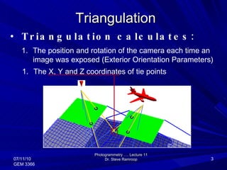
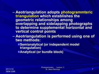
Lecture 11 Content Aerotriangulation (AO) Photogrammetry …. Lecture 11 Dr. Steve Ramroop 07/11/10 GEM 3366
Defined as the procedure of establishing the geometric relationships among overlapping and side lapping photographs for determining the positions of supplemental horizontal control points Reduces substantially the control required by field methods Photogrammetry …. Lecture 11 Dr. Steve Ramroop 07/11/10 GEM 3366
Triangulation Photogrammetry …. Lecture 11 Dr. Steve Ramroop 07/11/10 GEM 3366 Triangulation calculates: The position and rotation of the camera each time an image was exposed (Exterior Orientation Parameters)  The X, Y and Z coordinates of tie points
Overlap between Runs or Swaths Photogrammetry …. Lecture 11 Dr. Steve Ramroop 07/11/10 GEM 3366 30% overlap between  runs or swaths Run #1 Run #2
What is a BLOCK? A BLOCK is all the information needed to triangulate a set of air photographs in one process  Photogrammetry …. Lecture 11 Dr. Steve Ramroop 07/11/10 GEM 3366 This must include: 4. Projection, Spheroid, Datum Information 1. Photographs or images  2. Camera information 3. Control X,Y,Z
What is a BLOCK? A Block created in Stereo Analyst contains two overlapping images (a Stereo Pair).  Photogrammetry …. Lecture 11 Dr. Steve Ramroop 07/11/10 GEM 3366 60% Overlap
Aeotriangulation adopts  photogrammteric triangulation  which establishes the geometric relationships among overlapping and sidelapping photographs to determine supplemental horizontal and vertical control points Aeotriangulation is performed using one of two methods: Semianalytical (or independent model triangulation) Analytical (or bundle block) Photogrammetry …. Lecture 11 Dr. Steve Ramroop 07/11/10 GEM 3366
Semianalytical passes control from one model to the next Model’s relative orientation is done instrumentally on the plotter or analytically using a computer program, but the scale transfer between successive models is accomplished analytically Hence each model are independently generated Each model will have at least 3 tie points in common Photogrammetry …. Lecture 11 Dr. Steve Ramroop 07/11/10 GEM 3366
Relative orientation is done for each model and absolute orientation is done for the first model Use is made of the coordinates of the perspective centers of both photos (using the same coordinate system) as tie points Photogrammetry …. Lecture 11 Dr. Steve Ramroop 07/11/10 GEM 3366
Coordinates for the second overlap is transformed mathematically by making coordinates of the left-hand perspective center of the first overlap and then rotating the second coordinate system about its three axes to make the points coincide with the first overlap Photogrammetry …. Lecture 11 Dr. Steve Ramroop 07/11/10 GEM 3366
Photogrammetry …. Lecture 11 Dr. Steve Ramroop 07/11/10 GEM 3366
The perspective center coordinate provides a strong geometric tie between the models Tie points are computed using computer program that implements a transformation involving 7 parameters: 3 translations 3 rotations One scale change Photogrammetry …. Lecture 11 Dr. Steve Ramroop 07/11/10 GEM 3366
Photogrammetry …. Lecture 11 Dr. Steve Ramroop 07/11/10 GEM 3366
Tie points A TIE point is the image coordinate position of an object appearing on 2 or more images Photogrammetry …. Lecture 11 Dr. Steve Ramroop 07/11/10 GEM 3366 The X, Y and Z coordinates of a tie point are unknown and are determined by OrthoBASE during the aerial triangulation procedure
Analytical This is the second method of aerotriangulation Image point-measuring instruments (comparator, analytical plotter, workstation) are used to measure the x-y plate coordinates of each tie point and control point in each photograph Sequence of mathematical models are formed from which strip coordinates are derived Mathematical model represent the geometric relations between object space, perspective centers, and photographic images Photogrammetry …. Lecture 11 Dr. Steve Ramroop 07/11/10 GEM 3366
Image points are represented by their photographic coordinates measured  Input are photographic coordinates, camera parameters, and ground control points Use is made of the collinearity and coplanarity equations to manipulate the coordinates in a high speed computer Output of the computations are ground coordinates and elevations of the tie points Ideal tie points are the same points used in relative orientation Ability to correct for all possible systematic errors, such as film shrinkage, lens distortion, atmospheric refraction, and so on Photogrammetry …. Lecture 11 Dr. Steve Ramroop 07/11/10 GEM 3366
Block Residuals  Photogrammetry …. Lecture 11 Dr. Steve Ramroop 07/11/10 GEM 3366 There are RESIDUALS for: Each ground point Each image point Each perspective center Block of eight images… Least Squares Adjustment calculates new points based on distributing and minimizing residuals throughout the ENTIRE block Image & ground measurements
Spreading Error The adjustment distributes error throughout the block trying to minimize all the residuals You can control the adjustment process with the quality estimates  Photogrammetry …. Lecture 11 Dr. Steve Ramroop 07/11/10 GEM 3366 Measured Location Standard Deviation Predicted Location
When to stop? Least Squares is an iterative process. So, how does the process know when to stop adjusting the points and recalculating residuals? We define a threshold value in meters Convergence Value Once the process reaches convergence it stops What is convergence?… Photogrammetry …. Lecture 11 Dr. Steve Ramroop 07/11/10 GEM 3366
The Convergence Value After each iteration residuals calculated for each measurement Photogrammetry …. Lecture 11 Dr. Steve Ramroop 07/11/10 GEM 3366 0.912 0.282 0.513 0.589 0.766 0.054 0.386 0.054 0.674 0.195 0.054 0.049 If every difference between these values is less than the Convergence value, the iterations will STOP Indicates that the triangulation has met the required accuracy Iteration #1 #2 0.432 0.153 0.321 0.654 0.543 0.044 0.436 0.021 0.434 0.087 0.111 0.024
SCBA: How it works More GCPs an advantage (6 per overlap) Photogrammetry …. Lecture 11 Dr. Steve Ramroop 07/11/10 GEM 3366 SCBA will estimate the Interior Geometry of the sensor Self Calibrating and Bundle Adjustment Focal length Principal Point
Self-Calibrating Bundle Adjustment (SCBA) Cameras not designed for photogrammetry: Non-metric camera, digital camera or videography Cameras with outdated or no calibration reports Will estimate the interior orientation parameters of the camera/sensor Focal length Principal Point in the x direction Principal Point in the y direction Photogrammetry …. Lecture 11 Dr. Steve Ramroop 07/11/10 GEM 3366
…  The End … Photogrammetry …. Lecture 11 Dr. Steve Ramroop 07/11/10 GEM 3366

Photogrammetry - areaotriangulation

  • 1.
    Lecture 11 ContentAerotriangulation (AO) Photogrammetry …. Lecture 11 Dr. Steve Ramroop 07/11/10 GEM 3366
  • 2.
    Defined as theprocedure of establishing the geometric relationships among overlapping and side lapping photographs for determining the positions of supplemental horizontal control points Reduces substantially the control required by field methods Photogrammetry …. Lecture 11 Dr. Steve Ramroop 07/11/10 GEM 3366
  • 3.
    Triangulation Photogrammetry ….Lecture 11 Dr. Steve Ramroop 07/11/10 GEM 3366 Triangulation calculates: The position and rotation of the camera each time an image was exposed (Exterior Orientation Parameters) The X, Y and Z coordinates of tie points
  • 4.
    Overlap between Runsor Swaths Photogrammetry …. Lecture 11 Dr. Steve Ramroop 07/11/10 GEM 3366 30% overlap between runs or swaths Run #1 Run #2
  • 5.
    What is aBLOCK? A BLOCK is all the information needed to triangulate a set of air photographs in one process Photogrammetry …. Lecture 11 Dr. Steve Ramroop 07/11/10 GEM 3366 This must include: 4. Projection, Spheroid, Datum Information 1. Photographs or images 2. Camera information 3. Control X,Y,Z
  • 6.
    What is aBLOCK? A Block created in Stereo Analyst contains two overlapping images (a Stereo Pair). Photogrammetry …. Lecture 11 Dr. Steve Ramroop 07/11/10 GEM 3366 60% Overlap
  • 7.
    Aeotriangulation adopts photogrammteric triangulation which establishes the geometric relationships among overlapping and sidelapping photographs to determine supplemental horizontal and vertical control points Aeotriangulation is performed using one of two methods: Semianalytical (or independent model triangulation) Analytical (or bundle block) Photogrammetry …. Lecture 11 Dr. Steve Ramroop 07/11/10 GEM 3366
  • 8.
    Semianalytical passes controlfrom one model to the next Model’s relative orientation is done instrumentally on the plotter or analytically using a computer program, but the scale transfer between successive models is accomplished analytically Hence each model are independently generated Each model will have at least 3 tie points in common Photogrammetry …. Lecture 11 Dr. Steve Ramroop 07/11/10 GEM 3366
  • 9.
    Relative orientation isdone for each model and absolute orientation is done for the first model Use is made of the coordinates of the perspective centers of both photos (using the same coordinate system) as tie points Photogrammetry …. Lecture 11 Dr. Steve Ramroop 07/11/10 GEM 3366
  • 10.
    Coordinates for thesecond overlap is transformed mathematically by making coordinates of the left-hand perspective center of the first overlap and then rotating the second coordinate system about its three axes to make the points coincide with the first overlap Photogrammetry …. Lecture 11 Dr. Steve Ramroop 07/11/10 GEM 3366
  • 11.
    Photogrammetry …. Lecture11 Dr. Steve Ramroop 07/11/10 GEM 3366
  • 12.
    The perspective centercoordinate provides a strong geometric tie between the models Tie points are computed using computer program that implements a transformation involving 7 parameters: 3 translations 3 rotations One scale change Photogrammetry …. Lecture 11 Dr. Steve Ramroop 07/11/10 GEM 3366
  • 13.
    Photogrammetry …. Lecture11 Dr. Steve Ramroop 07/11/10 GEM 3366
  • 14.
    Tie points ATIE point is the image coordinate position of an object appearing on 2 or more images Photogrammetry …. Lecture 11 Dr. Steve Ramroop 07/11/10 GEM 3366 The X, Y and Z coordinates of a tie point are unknown and are determined by OrthoBASE during the aerial triangulation procedure
  • 15.
    Analytical This isthe second method of aerotriangulation Image point-measuring instruments (comparator, analytical plotter, workstation) are used to measure the x-y plate coordinates of each tie point and control point in each photograph Sequence of mathematical models are formed from which strip coordinates are derived Mathematical model represent the geometric relations between object space, perspective centers, and photographic images Photogrammetry …. Lecture 11 Dr. Steve Ramroop 07/11/10 GEM 3366
  • 16.
    Image points arerepresented by their photographic coordinates measured Input are photographic coordinates, camera parameters, and ground control points Use is made of the collinearity and coplanarity equations to manipulate the coordinates in a high speed computer Output of the computations are ground coordinates and elevations of the tie points Ideal tie points are the same points used in relative orientation Ability to correct for all possible systematic errors, such as film shrinkage, lens distortion, atmospheric refraction, and so on Photogrammetry …. Lecture 11 Dr. Steve Ramroop 07/11/10 GEM 3366
  • 17.
    Block Residuals Photogrammetry …. Lecture 11 Dr. Steve Ramroop 07/11/10 GEM 3366 There are RESIDUALS for: Each ground point Each image point Each perspective center Block of eight images… Least Squares Adjustment calculates new points based on distributing and minimizing residuals throughout the ENTIRE block Image & ground measurements
  • 18.
    Spreading Error Theadjustment distributes error throughout the block trying to minimize all the residuals You can control the adjustment process with the quality estimates Photogrammetry …. Lecture 11 Dr. Steve Ramroop 07/11/10 GEM 3366 Measured Location Standard Deviation Predicted Location
  • 19.
    When to stop?Least Squares is an iterative process. So, how does the process know when to stop adjusting the points and recalculating residuals? We define a threshold value in meters Convergence Value Once the process reaches convergence it stops What is convergence?… Photogrammetry …. Lecture 11 Dr. Steve Ramroop 07/11/10 GEM 3366
  • 20.
    The Convergence ValueAfter each iteration residuals calculated for each measurement Photogrammetry …. Lecture 11 Dr. Steve Ramroop 07/11/10 GEM 3366 0.912 0.282 0.513 0.589 0.766 0.054 0.386 0.054 0.674 0.195 0.054 0.049 If every difference between these values is less than the Convergence value, the iterations will STOP Indicates that the triangulation has met the required accuracy Iteration #1 #2 0.432 0.153 0.321 0.654 0.543 0.044 0.436 0.021 0.434 0.087 0.111 0.024
  • 21.
    SCBA: How itworks More GCPs an advantage (6 per overlap) Photogrammetry …. Lecture 11 Dr. Steve Ramroop 07/11/10 GEM 3366 SCBA will estimate the Interior Geometry of the sensor Self Calibrating and Bundle Adjustment Focal length Principal Point
  • 22.
    Self-Calibrating Bundle Adjustment(SCBA) Cameras not designed for photogrammetry: Non-metric camera, digital camera or videography Cameras with outdated or no calibration reports Will estimate the interior orientation parameters of the camera/sensor Focal length Principal Point in the x direction Principal Point in the y direction Photogrammetry …. Lecture 11 Dr. Steve Ramroop 07/11/10 GEM 3366
  • 23.
    … TheEnd … Photogrammetry …. Lecture 11 Dr. Steve Ramroop 07/11/10 GEM 3366