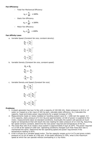
LECTURE UNIT NO. 9
Fans and Blowers
A fan is a machine used to apply power to a gas to increase energy content thereby causing it to flow or
move.
A blower is a fan used to force air under pressure which means resistance to gas flow is imposed upon
discharge.
An exhauster is a fan used to withdraw air under suction, that is, the resistance to gas flow is imposed
primarily upon the inlet.
Functions of Fans
   1. To move air or gasses through distribution systems and apparatus required for conditioning of
        buildings.
   2. For drying and cooling.
   3. For pneumatic conveying.
   4. For dust collection, separation and exhaust.
   5. For mine and tunnel ventilation.
   6. For forced and induced draft of steam generating units.
Basic Elements in Fan Design
   1. Wheel or impeller
             -   the rotating member.
   2. Housing
             -   stationary member provided with an intake opening (inlet) and a discharge opening (outlet).
Basic Difference According to the American Society of Mechanical Engineers (ASME)
   1. Fan – if the pressure rise is equal to or below 1 psig.
   2. Blower – if the pressure rise is between 50 to 1 psig.
   3. Compressor – if the pressure rise is above 50 psig.
Factors Affecting Fan Selection
   1. Quantity of gas (or air) to be moved per unit time.
   2. Estimated resistance and expected variations.
   3. Amount of noise permitted.
   4. Space available for the fan.
   5. Economic implications.
Fan Control
        Regulation of fan capacity or varying the volume delivered
   1. Damper control
                 Simplest method. Dampering is a throttling action applied to the gas flow.
   2. Inlet vane control
                 Series of adjustable position vanes at fan inlet to control air entering the wheel.
   3. Variable speed control
                 Controls the speed of the motor.
Total Air Power


Fan Capacity
      Q=Av
Energy Equation
      From Law of Conservation of Energy
Basic Assumption:
      1. Considering inlet and discharge static pressure
      2. Considering inlet and discharge velocities
      3. Constant temperature
                                             [Ein = Eout]
             PEs + KEs + Us + Wfs + Air Power = PEd + KEd + Ud + Wfd
                      Us, Ud = 0, since change in temperature is minimal.
                      ΔPE = 0


               Let:
                      Hv = velocity head / velocity pressure head


                      Hs = static head / static pressure head


                      Ht = total head / total fan pressure head
                             Ht = Hv + Hs
Static Air Power
      Ps = Q γa H s


Static Pressure Head


                      Relationship:
                             γa Hs = γw hw
Fan Efficiency
          -   Total Fan Mechanical Efficiency


          -   Static Fan Efficiency


          -   Motor Fan Efficiency


Fan Affinity Laws
   a. Variable Speed (Constant fan size, constant density)


   b. Variable Density (Constant fan size, constant speed)


   c. Variable Density and Speed (Constant fan size)


Problems:
   1. A steam generator has two f-d fan with a capacity of 150 000 cfm. Static pressure is 10.5 in. of
      water (a.) based on a fan input of 345 hp each, calculate static efficiency. (b.) Calculate the
      capacity, head and brake power requirements for a speed increase of 15%.
   2. Measurements made on newly installed air handling system were N = 1200 rpm fan speed. 2.4
      m3/s capacity, static pressure of 3 mm Hg and approximately 1.8 kW of power is supplied to the
      motor, measurements taken at standard conditions. Eventually the system will operate at much
      higher air temperature that will result into new reading for static pressure of 2.5 mm Hg. Assuming
      fan speed remains constant, determine the new power required and temperature of the air.
   3. The mass flow rate of air inside a duct system is approximately 6 kg/s at 20°C. The power required
      is 5.5 kW at fan speed of 1200 rpm. Operating conditions changed such that mass flow rate is
      maintained the same. Determine the fan operating speed and power requirement if the
      temperature reading is 45°C.
   4. A fan is driven by a variable speed motor. The fan capacity ranges up to 4 m 3/s and gives a static
      pressure of 14 cm of water at 1700 rpm. If the static efficiency is 70%, what is the maximum
      speed at which fan can operate without overloading a 11 hp motor.
009
009

009

  • 1.
    LECTURE UNIT NO.9 Fans and Blowers A fan is a machine used to apply power to a gas to increase energy content thereby causing it to flow or move. A blower is a fan used to force air under pressure which means resistance to gas flow is imposed upon discharge. An exhauster is a fan used to withdraw air under suction, that is, the resistance to gas flow is imposed primarily upon the inlet. Functions of Fans 1. To move air or gasses through distribution systems and apparatus required for conditioning of buildings. 2. For drying and cooling. 3. For pneumatic conveying. 4. For dust collection, separation and exhaust. 5. For mine and tunnel ventilation. 6. For forced and induced draft of steam generating units. Basic Elements in Fan Design 1. Wheel or impeller - the rotating member. 2. Housing - stationary member provided with an intake opening (inlet) and a discharge opening (outlet). Basic Difference According to the American Society of Mechanical Engineers (ASME) 1. Fan – if the pressure rise is equal to or below 1 psig. 2. Blower – if the pressure rise is between 50 to 1 psig. 3. Compressor – if the pressure rise is above 50 psig. Factors Affecting Fan Selection 1. Quantity of gas (or air) to be moved per unit time. 2. Estimated resistance and expected variations. 3. Amount of noise permitted. 4. Space available for the fan. 5. Economic implications. Fan Control Regulation of fan capacity or varying the volume delivered 1. Damper control Simplest method. Dampering is a throttling action applied to the gas flow. 2. Inlet vane control Series of adjustable position vanes at fan inlet to control air entering the wheel. 3. Variable speed control Controls the speed of the motor.
  • 2.
    Total Air Power FanCapacity Q=Av Energy Equation From Law of Conservation of Energy Basic Assumption: 1. Considering inlet and discharge static pressure 2. Considering inlet and discharge velocities 3. Constant temperature [Ein = Eout] PEs + KEs + Us + Wfs + Air Power = PEd + KEd + Ud + Wfd Us, Ud = 0, since change in temperature is minimal. ΔPE = 0 Let: Hv = velocity head / velocity pressure head Hs = static head / static pressure head Ht = total head / total fan pressure head Ht = Hv + Hs Static Air Power Ps = Q γa H s Static Pressure Head Relationship: γa Hs = γw hw
  • 3.
    Fan Efficiency - Total Fan Mechanical Efficiency - Static Fan Efficiency - Motor Fan Efficiency Fan Affinity Laws a. Variable Speed (Constant fan size, constant density) b. Variable Density (Constant fan size, constant speed) c. Variable Density and Speed (Constant fan size) Problems: 1. A steam generator has two f-d fan with a capacity of 150 000 cfm. Static pressure is 10.5 in. of water (a.) based on a fan input of 345 hp each, calculate static efficiency. (b.) Calculate the capacity, head and brake power requirements for a speed increase of 15%. 2. Measurements made on newly installed air handling system were N = 1200 rpm fan speed. 2.4 m3/s capacity, static pressure of 3 mm Hg and approximately 1.8 kW of power is supplied to the motor, measurements taken at standard conditions. Eventually the system will operate at much higher air temperature that will result into new reading for static pressure of 2.5 mm Hg. Assuming fan speed remains constant, determine the new power required and temperature of the air. 3. The mass flow rate of air inside a duct system is approximately 6 kg/s at 20°C. The power required is 5.5 kW at fan speed of 1200 rpm. Operating conditions changed such that mass flow rate is maintained the same. Determine the fan operating speed and power requirement if the temperature reading is 45°C. 4. A fan is driven by a variable speed motor. The fan capacity ranges up to 4 m 3/s and gives a static pressure of 14 cm of water at 1700 rpm. If the static efficiency is 70%, what is the maximum speed at which fan can operate without overloading a 11 hp motor.