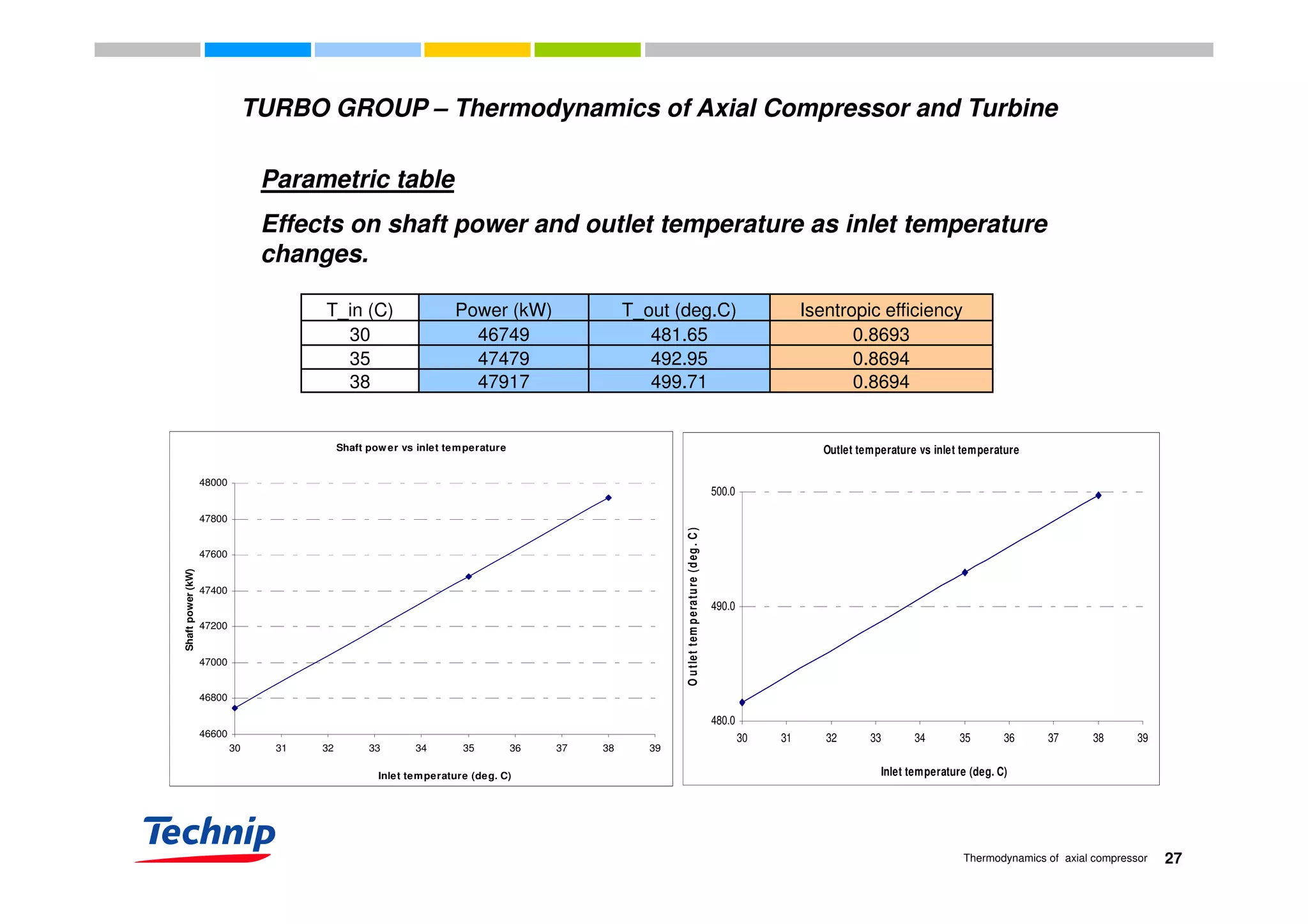
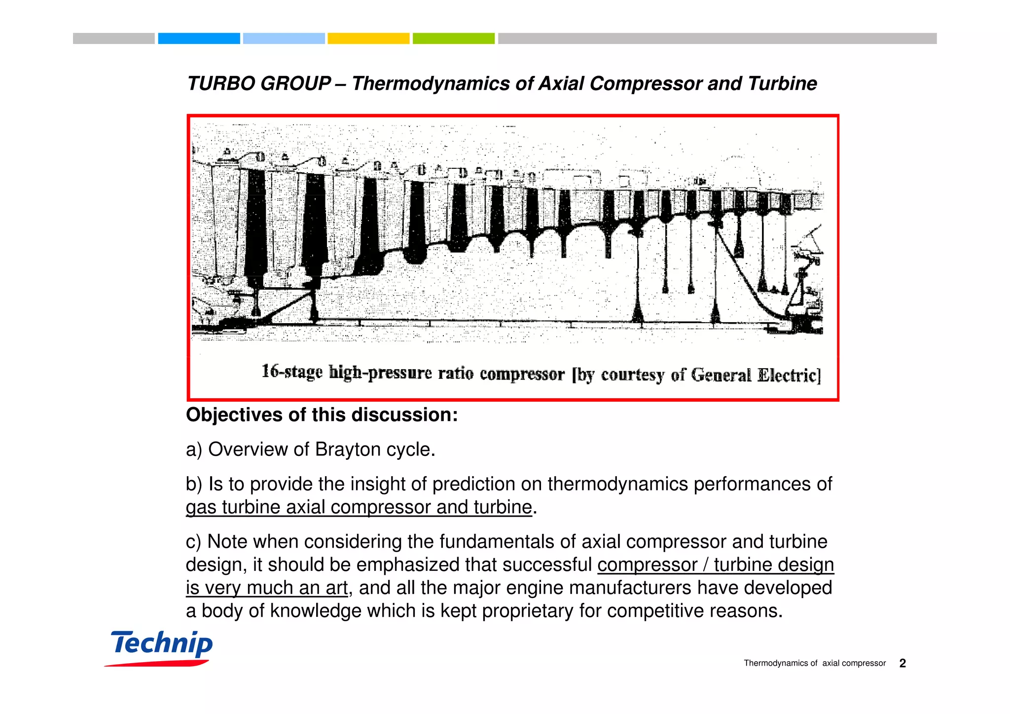
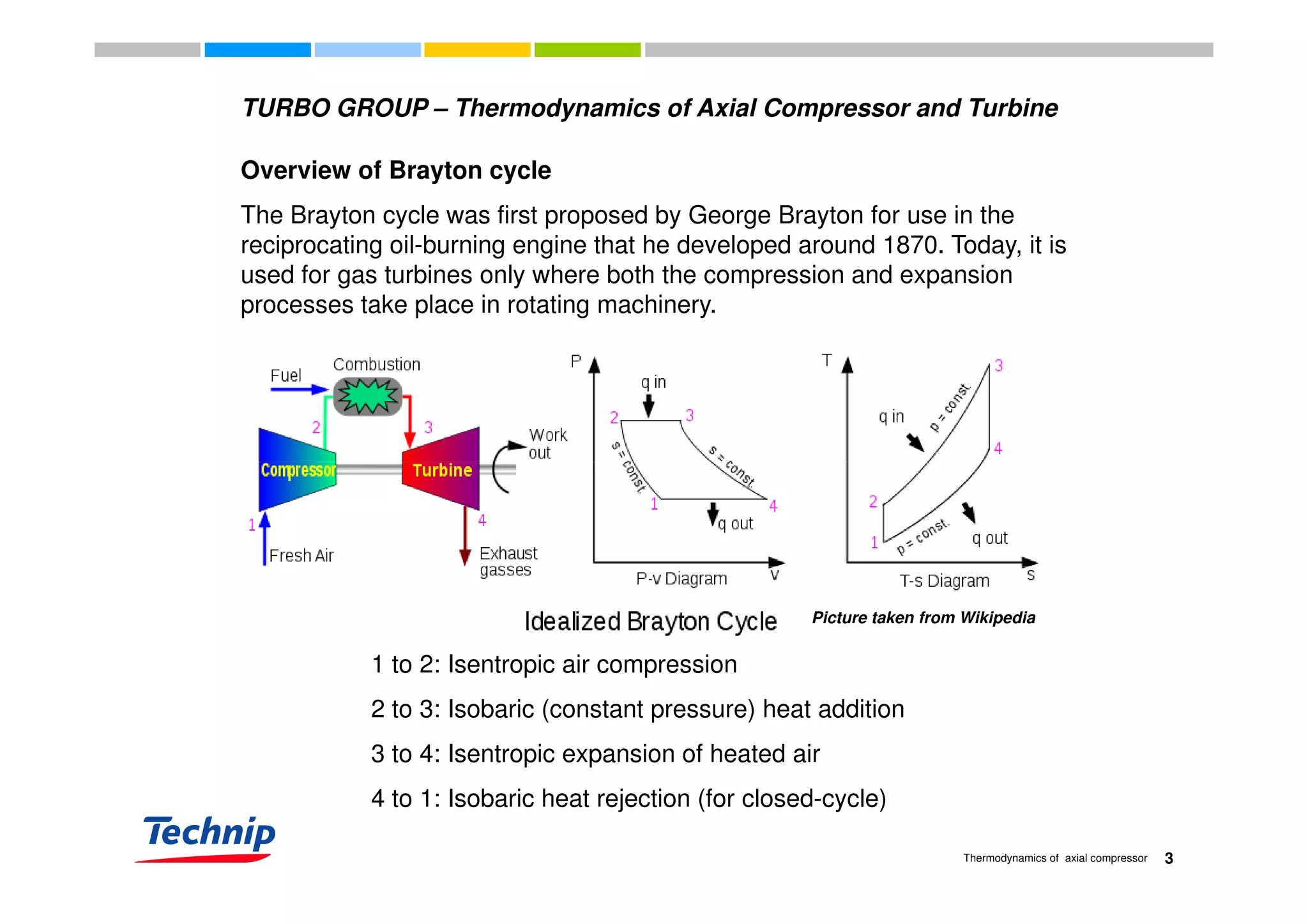
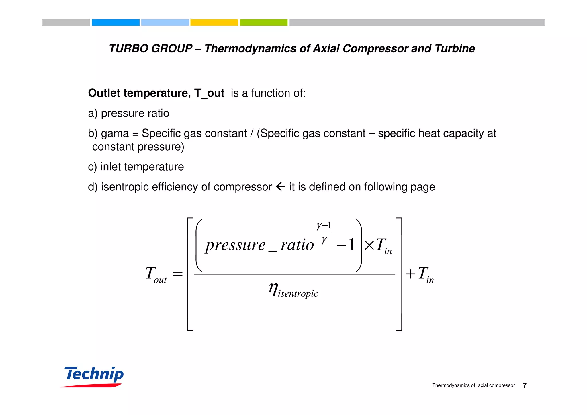
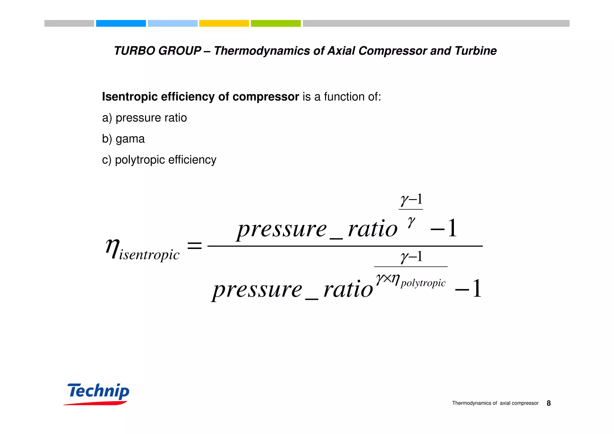
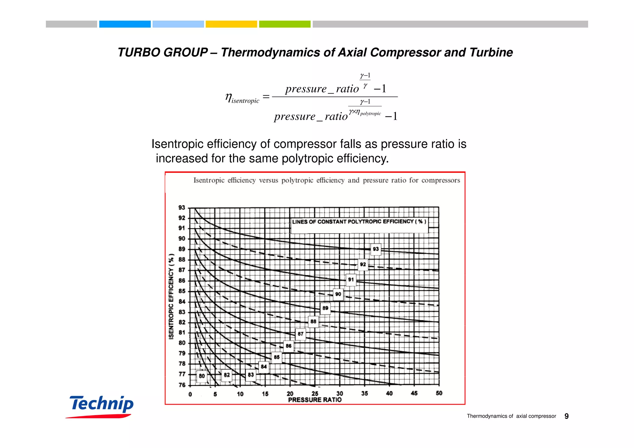
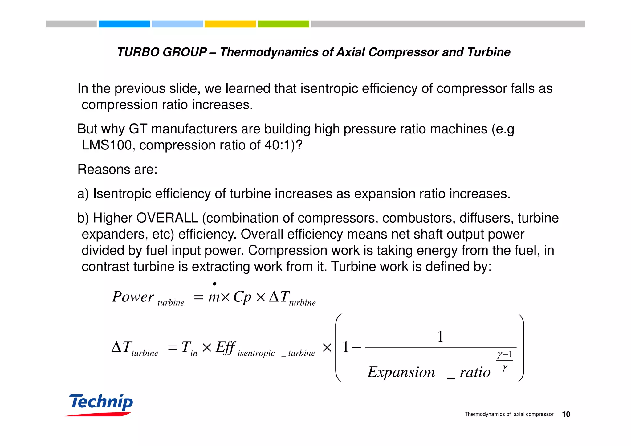
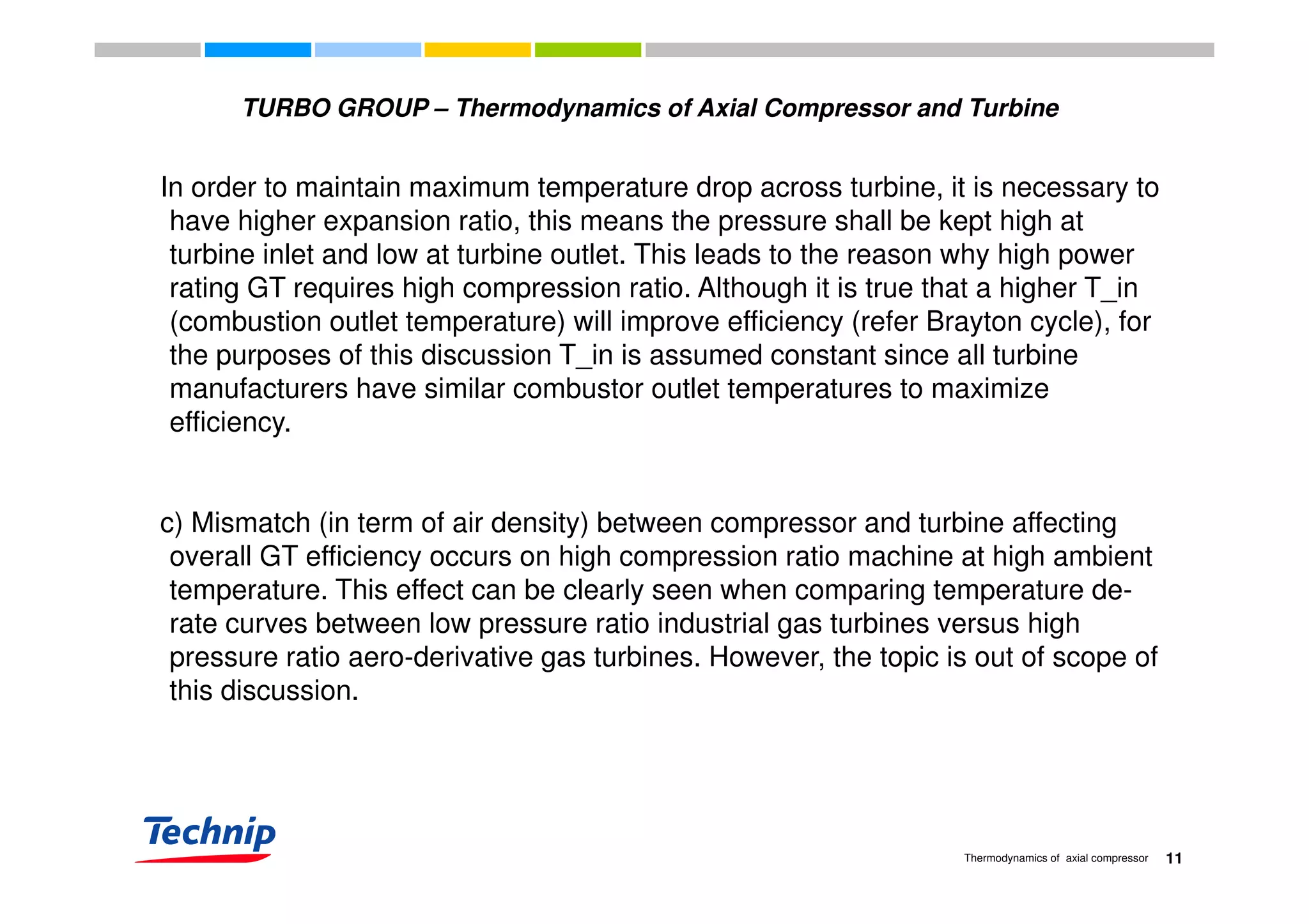
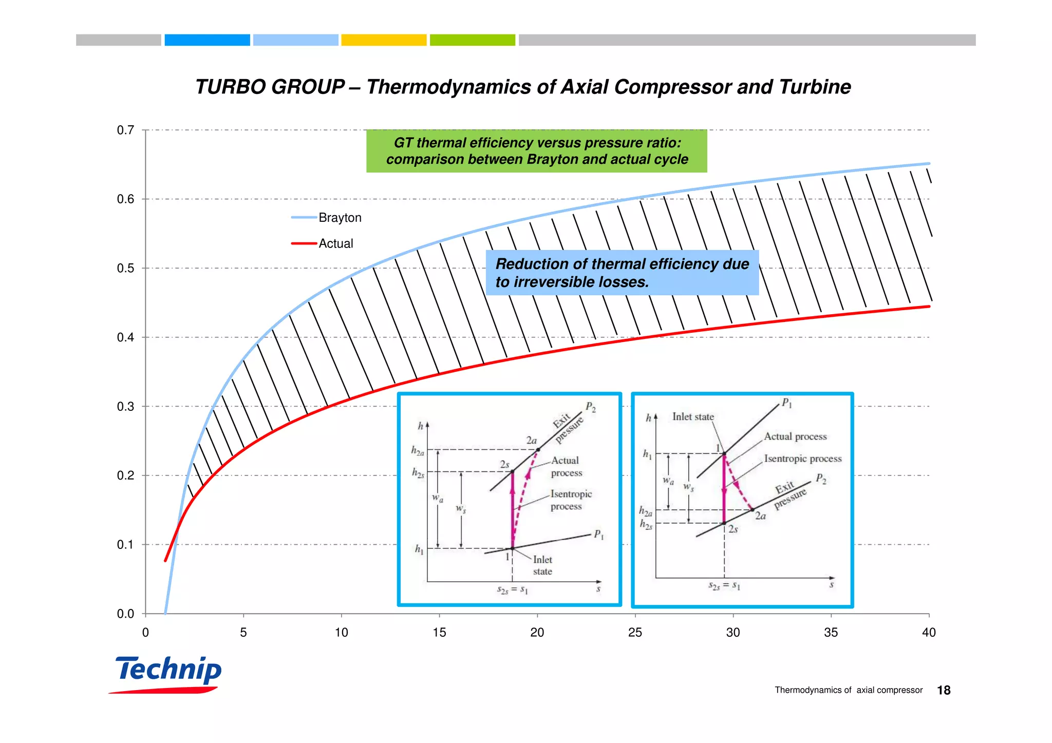
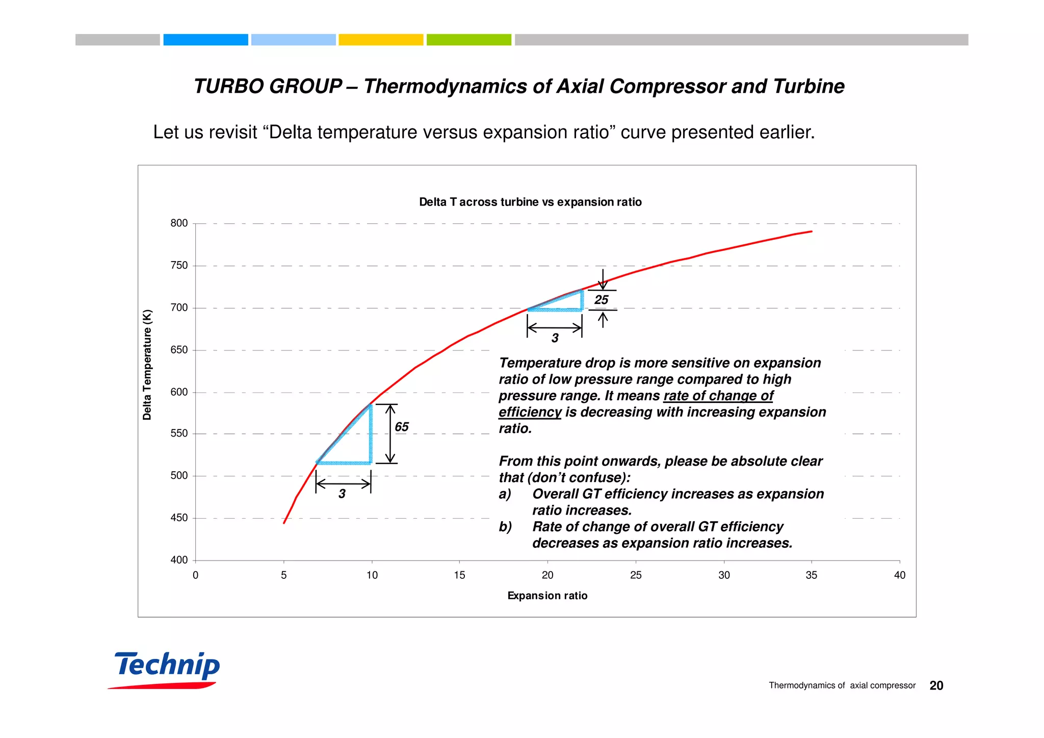
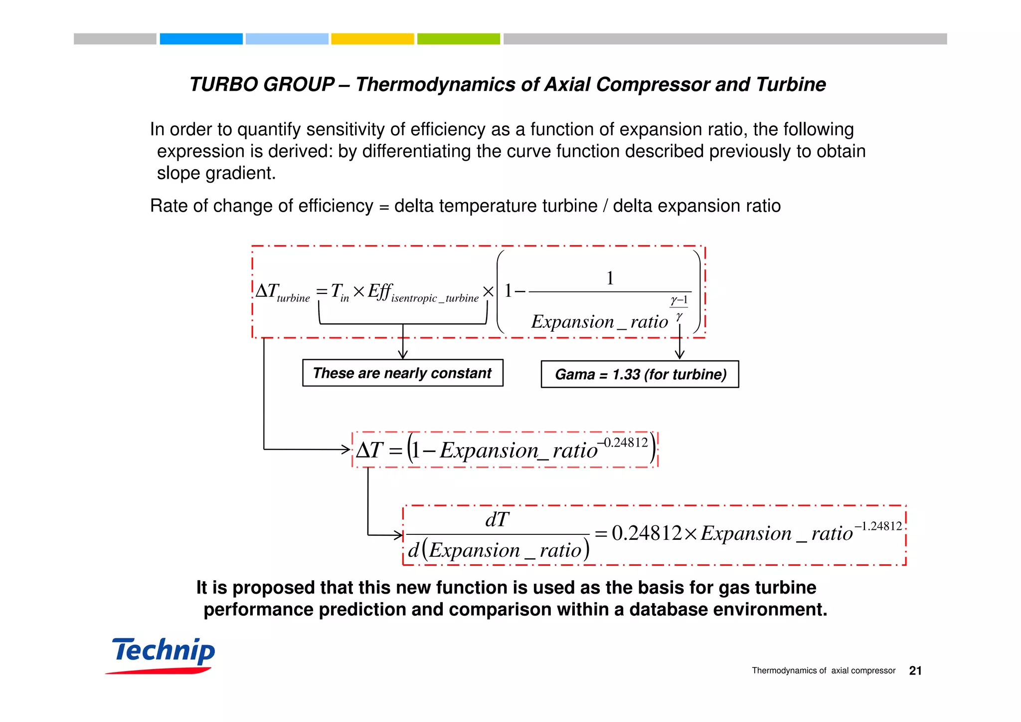
This document discusses the thermodynamics of axial compressors and turbines used in gas turbines. It provides an overview of the Brayton cycle and discusses how to calculate the shaft power required for compression, temperature rises in the compressor, and outlet temperature as a function of pressure ratio, inlet temperature, and isentropic efficiency. Higher compression ratios are desirable because they increase turbine efficiency and overall gas turbine efficiency, though the rate of efficiency improvement decreases at higher ratios. Designing high-efficiency machines requires balancing increased efficiency from high compression against diminishing returns.
![TURBO GROUP – Thermodynamics of Axial Compressor and Turbine
2.00
Specific work output vs pressure ratio T3/T1 = 2
T3/T1 = 3
T3/T1 = 4
T3/T1 = 5
1.50
T_in)]
T3/T1 = 5
1.00
Specificworkoutput[W/(Cp*T_in
0.50
Specificworkoutput[W/(
0.00
0 5 10 15 20 25 30
-0.50
Pressure ratio
14Thermodynamics of axial compressor](https://image.slidesharecdn.com/b6b4ad0d-3c23-4467-8faa-8024eef1aa51-160823151017/75/Thermodynamics-of-axial-compressor-and-turbine-3rd-December-2009-14-2048.jpg)
![TURBO GROUP – Thermodynamics of Axial Compressor and Turbine
2.00
Specific work output vs pressure ratio T3/T1 = 2
T3/T1 = 3
T3/T1 = 4
1.50
T_in)]
T3/T1 = 5
PR=17
1.00
Specificworkoutput[W/(Cp*T_in
PR=17
Optimum pressure ratio for a
0.50
Specificworkoutput[W/(
PR=11
Optimum pressure ratio for a
given temperature ratio, T3/T1.
0.00
0 5 10 15 20 25 30
Specificworkoutput[W/(
PR=7
PR=3
-0.50
Pressure ratio
15Thermodynamics of axial compressor
Pressure ratio](https://image.slidesharecdn.com/b6b4ad0d-3c23-4467-8faa-8024eef1aa51-160823151017/75/Thermodynamics-of-axial-compressor-and-turbine-3rd-December-2009-15-2048.jpg)
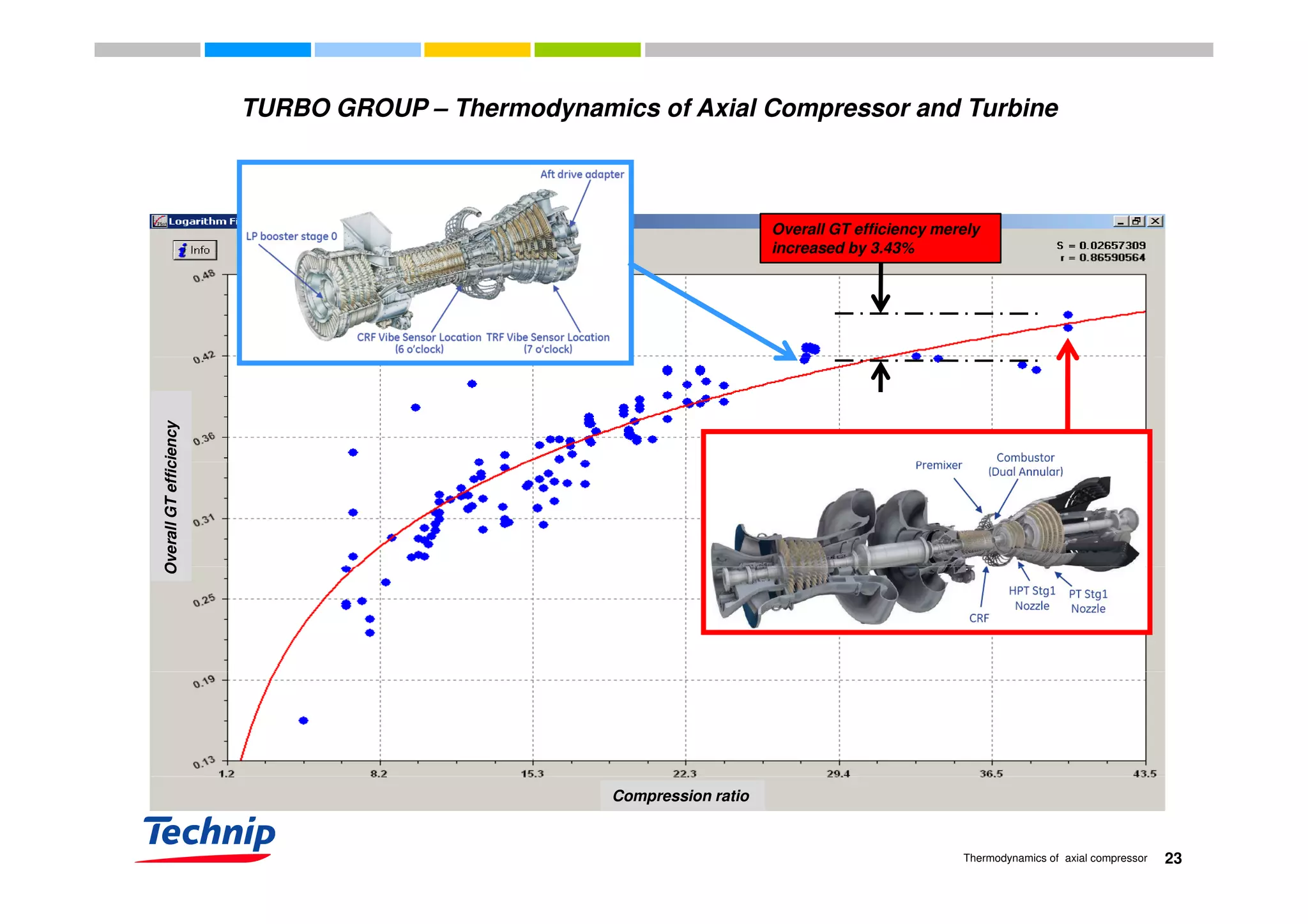
![OVERALL (combination of compressors, combustors, diffusers, turbine expanders, etc) efficiency
TURBO GROUP – Thermodynamics of Axial Compressor and Turbine
OVERALL (combination of compressors, combustors, diffusers, turbine expanders, etc) efficiency
increases as compression ratio increases.
Overall GT efficiency versus compression ratio
OverallgasturbineefficiencyOverallgasturbineefficiencyOverallgasturbineefficiency
( )rationcompressiooverall _ln09979.007641.0 ×+=η ( )rationcompressiooverall _ln09979.007641.0 ×+=η
Note: Overall GT efficiency is derived from machine manufacturers’
published heat rate..
Compression ratio
Gas turbine heat rate data courtesy of James Bryan
[GSGnet.net (2009)]
16Thermodynamics of axial compressor
Compression ratio](https://image.slidesharecdn.com/b6b4ad0d-3c23-4467-8faa-8024eef1aa51-160823151017/75/Thermodynamics-of-axial-compressor-and-turbine-3rd-December-2009-16-2048.jpg)
![TURBO GROUP – Thermodynamics of Axial Compressor and Turbine
Rate of change of overall GT efficiency as a function of expansion ratio is now defined:
( )
24812.1
_24812.0
_
−
×= ratioExpansion
ratioExpansiond
dT
( )ratioExpansiond
dT
_ ( )_ ratioExpansiond
0.12
This curve (dT/d[expansion ratio]) enables us to visualize how sensitive is
overall GT efficiency as a function of expansion ratio.
( )ratioExpansiond _
0.08
0.1
overall GT efficiency as a function of expansion ratio.
LM 6000
Compression ratio = 28.1
LMS 100
Compression ratio = 40
0.06
0.08
0.04
0
0.02
0 10 20 30 40 50 60
22Thermodynamics of axial compressor
0 10 20 30 40 50 60
Expansion
ratio](https://image.slidesharecdn.com/b6b4ad0d-3c23-4467-8faa-8024eef1aa51-160823151017/75/Thermodynamics-of-axial-compressor-and-turbine-3rd-December-2009-22-2048.jpg)
![TURBO GROUP – Thermodynamics of Axial Compressor and Turbine
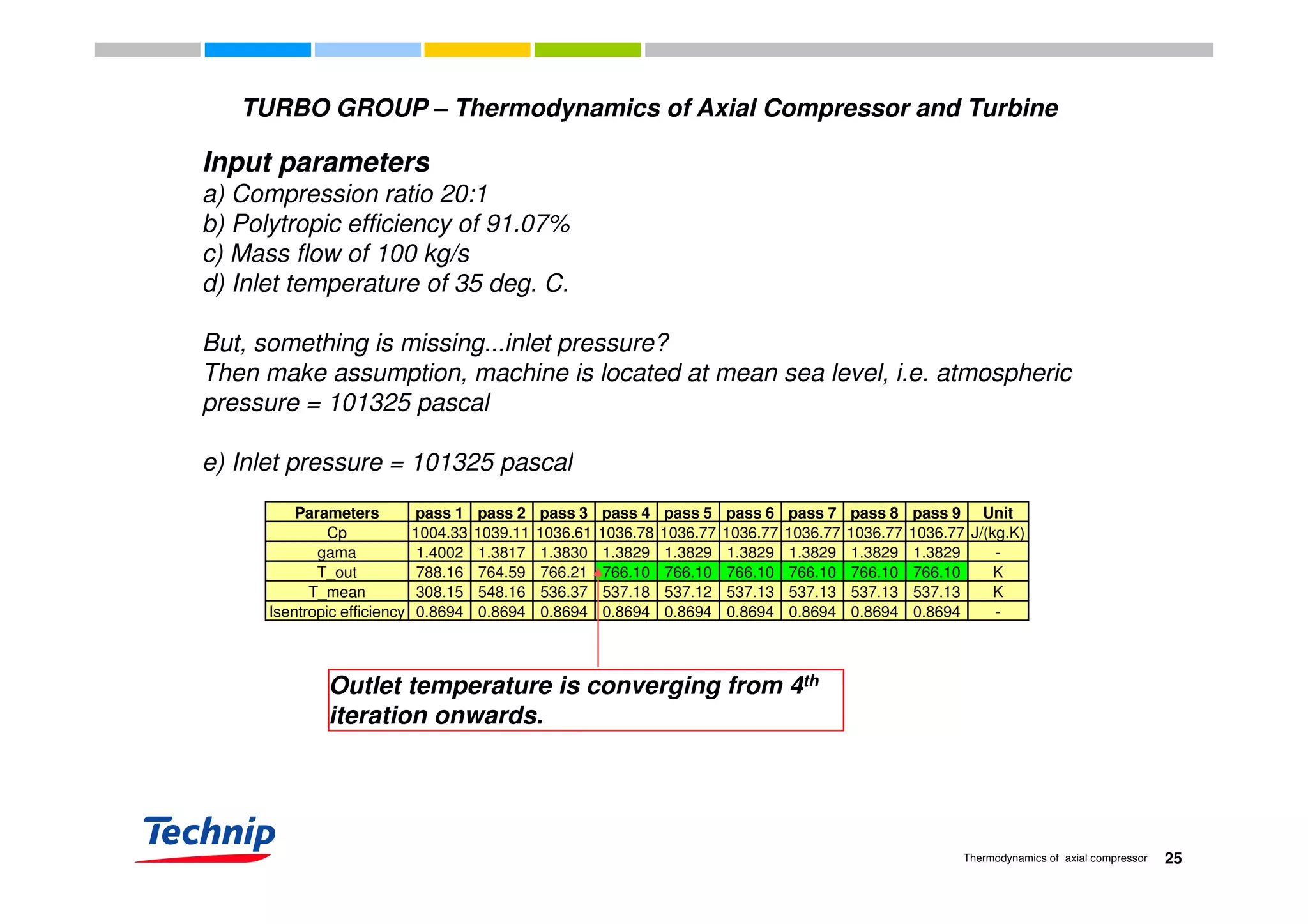
Parameters pass 1 pass 2 pass 3 pass 4 pass 5 pass 6 pass 7 pass 8 pass 9 Unit
Cp 1004.33 1039.11 1036.61 1036.78 1036.77 1036.77 1036.77 1036.77 1036.77 J/(kg.K)
gama 1.4002 1.3817 1.3830 1.3829 1.3829 1.3829 1.3829 1.3829 1.3829 -gama 1.4002 1.3817 1.3830 1.3829 1.3829 1.3829 1.3829 1.3829 1.3829 -
T_out 788.16 764.59 766.21 766.10 766.10 766.10 766.10 766.10 766.10 K
T_mean 308.15 548.16 536.37 537.18 537.12 537.13 537.13 537.13 537.13 K
Isentropic efficiency 0.8694 0.8694 0.8694 0.8694 0.8694 0.8694 0.8694 0.8694 0.8694 -
Outlet temperature, T_out = 766.10 K or 492.95 deg. C
Shaft power = 100 (kg/s) x 1036.77 (J/kg.K) x [766.10 - 308.15] (K)
= 100 x 1036.77 x 457.95= 100 x 1036.77 x 457.95
= 47478882.15 J/s
= 47479 kW
26Thermodynamics of axial compressor](https://image.slidesharecdn.com/b6b4ad0d-3c23-4467-8faa-8024eef1aa51-160823151017/75/Thermodynamics-of-axial-compressor-and-turbine-3rd-December-2009-26-2048.jpg)