Download to read offline

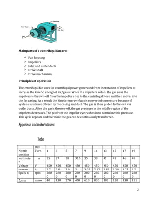
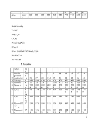
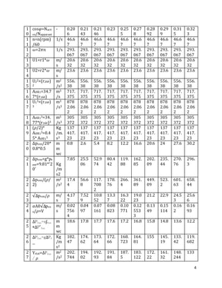
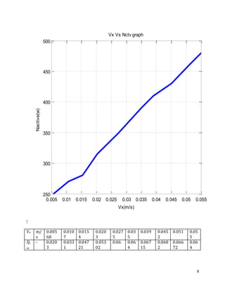
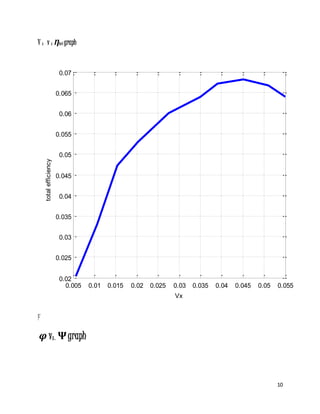
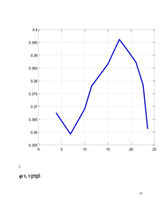
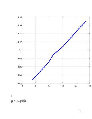

1) The objectives of the lab were to measure total and static pressure drop with respect to flow rate and determine the parameters that most affect fan operation capacity and efficiency. 2) A centrifugal fan works by accelerating air radially using rotating impellers which increase kinetic energy and convert it to pressure to move air against resistance. Key parts include the housing, impellers, ducts, drive shaft, and mechanism. 3) Tests were conducted to collect data on pressure drop, voltage, current, speed, and other parameters at increasing nozzle positions to analyze fan performance characteristics such as effective power and total efficiency.


