The document summarizes key concepts from the second law of thermodynamics:
1) The first law has limitations in predicting whether an energy conversion is possible. The second law addresses this through statements by Kelvin-Planck and Clausius.
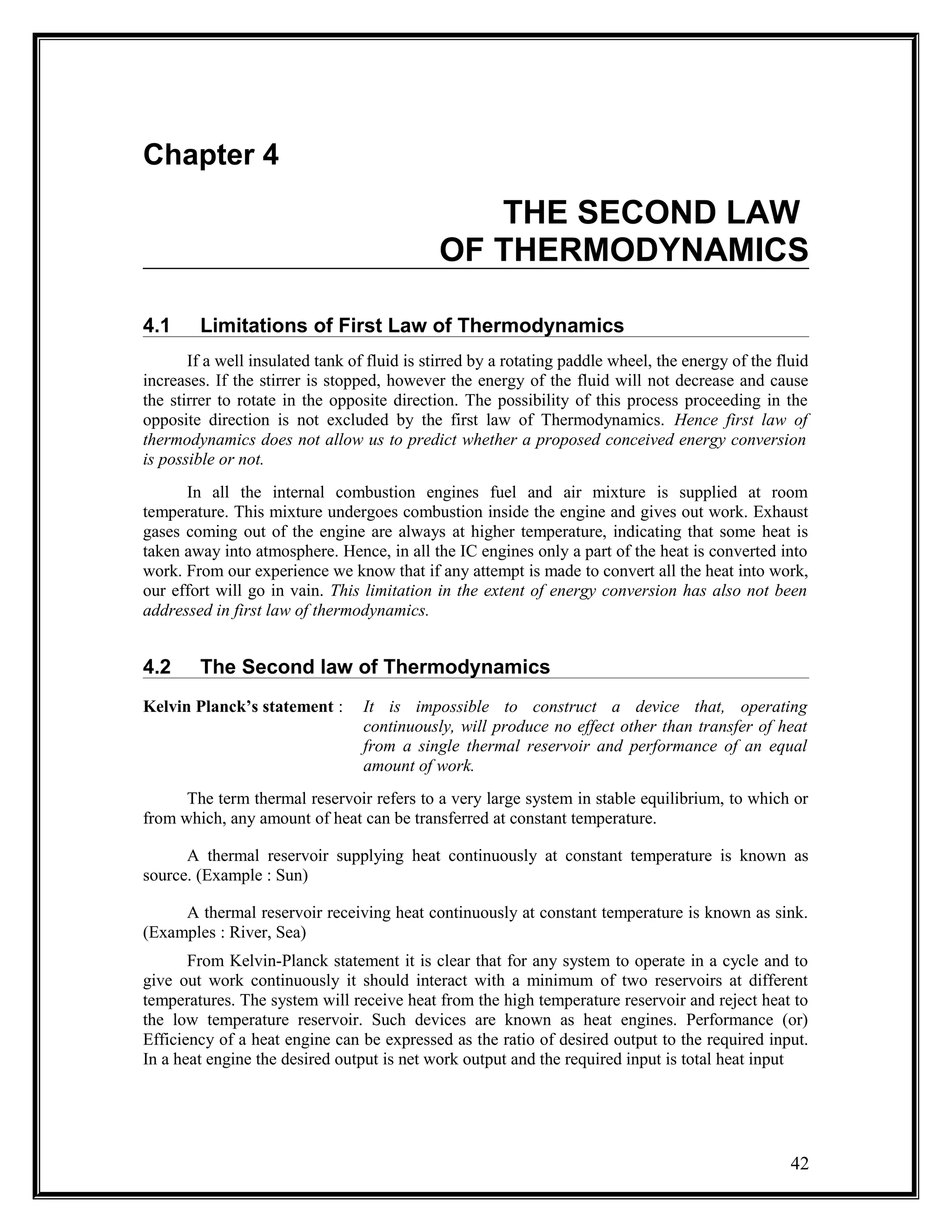
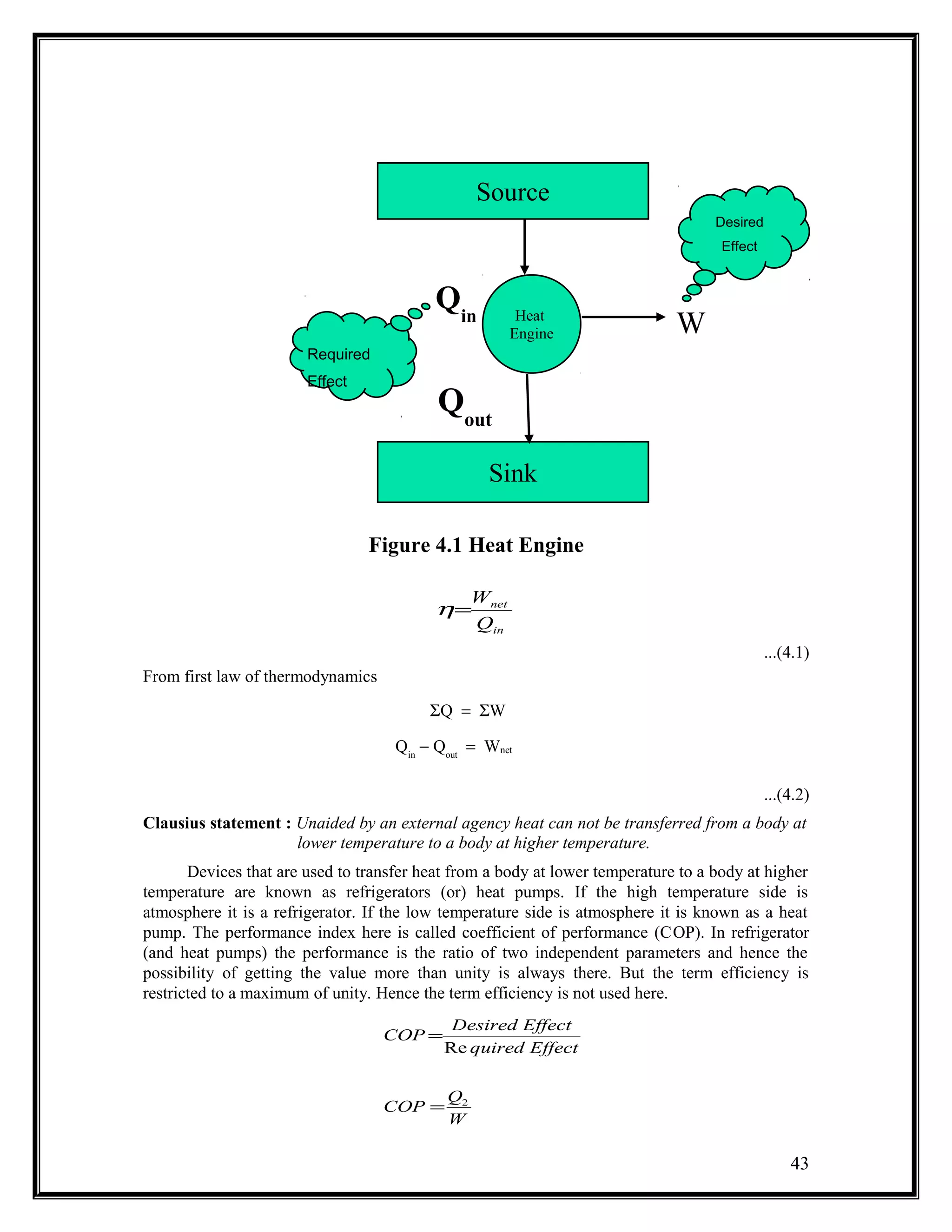
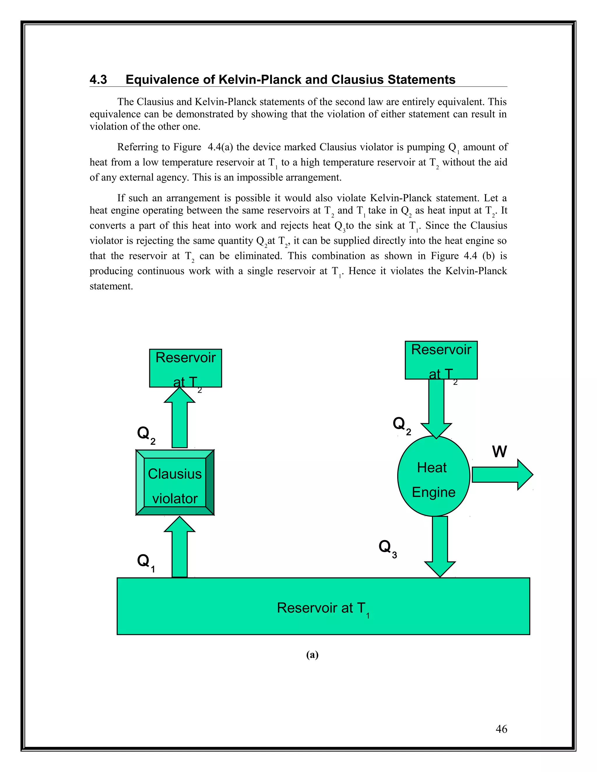
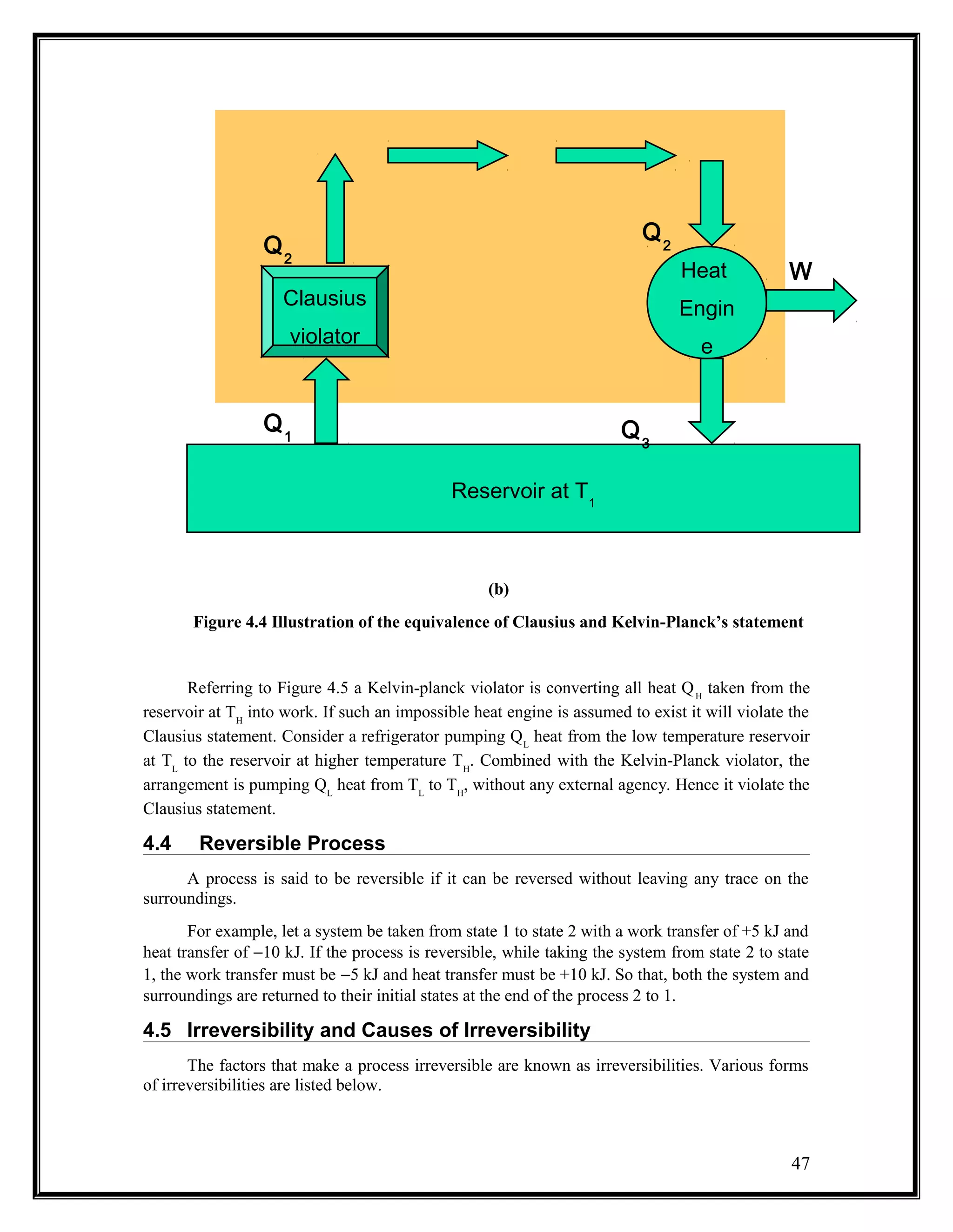
2) Kelvin-Planck's statement says a device cannot produce work without transferring heat from a hot reservoir and into a cold one. Clausius' statement says heat cannot spontaneously flow from cold to hot.
3) A reversible process can be reversed without leaving traces. Irreversible processes like friction cause a loss of useful energy.
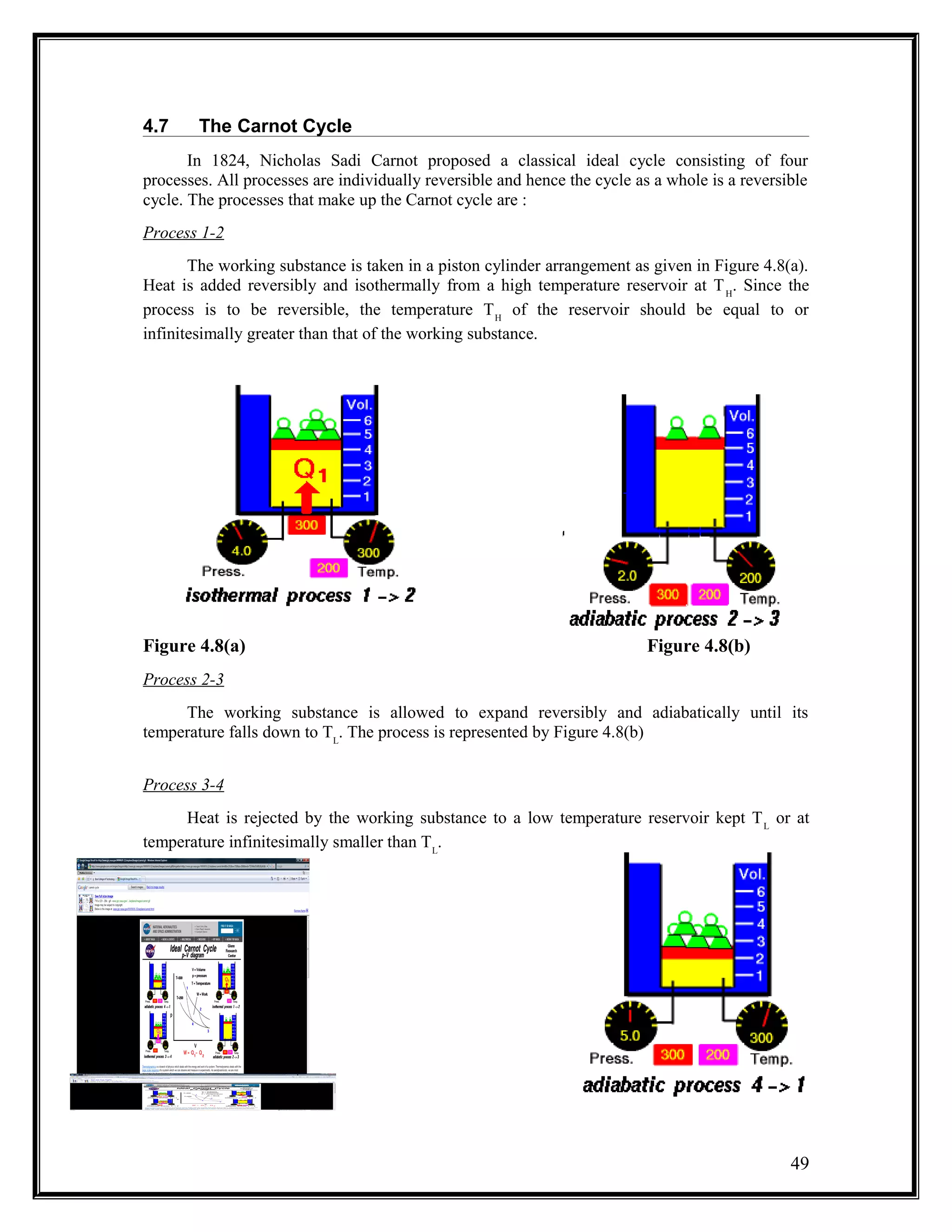
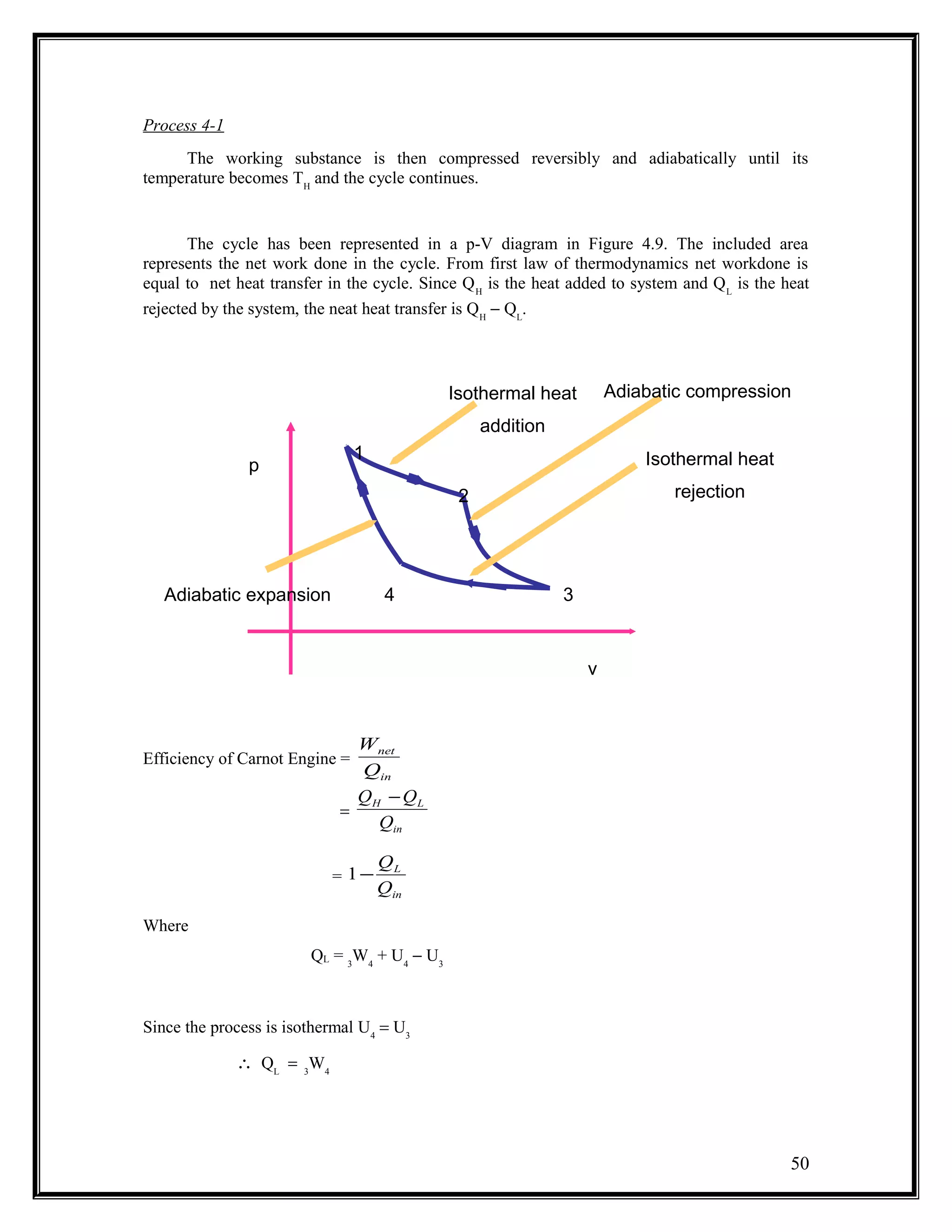
4) The Carnot cycle uses reversible, isothermal and adiabatic processes between two reservoirs to produce work
![Taking work as external agency, for refrigerators (Figure 4.2)
...(4.3)
From first law
ΣQ = ΣW
Q1
− Q2
= W
Figure 4.2 Refrigerator
Sink
[Atmosphere]
Refrig
erator
Source
[conditioned Space]
W
Q1
Q2
Desired
Effect
Require
d Effect
44
21
2
QQ
Q
COP
−
=](https://image.slidesharecdn.com/chapter4-secondlaw-141104004550-conversion-gate02/75/Chapter-4-second-law-3-2048.jpg)
![Figure 4.3 Heat Pump
Similarly for a heat pumps (Figure 4.3)
...(4.4)
...(4.5)
Sink
[Conditioned Space]
Heat
Pump
Source
[Atmosphere]
W
Q1
Q2
Require
d
Effect
Desired
Effect
45
21
1
21
1
,
Re
QQ
Q
COP
WQQSince
W
Q
COP
Effectquired
EffectDesired
COP
−
=
=+
=
=](https://image.slidesharecdn.com/chapter4-secondlaw-141104004550-conversion-gate02/75/Chapter-4-second-law-4-2048.jpg)


![[Solution manual] fluid mechanics fox & mcdonald](https://cdn.slidesharecdn.com/ss_thumbnails/solutionmanualfluidmechanicsfoxmcdonaldwww-141204014630-conversion-gate02-thumbnail.jpg?width=640&height=640&fit=bounds)


