This document contains equations related to air flow generated by fans and nozzles. It includes equations for:
1) The theoretical pressure difference generated by a fan based on changes in absolute and relative velocity.
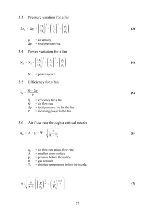
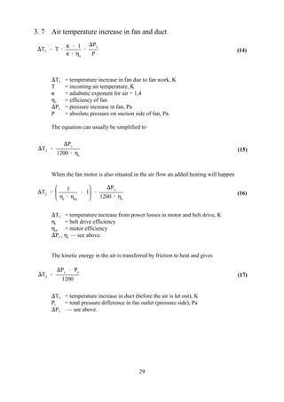
2) How flow rate, pressure, power, and efficiency of a fan vary with changes in rotational velocity and diameter.
3) How air flow rate through a critical nozzle depends on pressure, temperature, and nozzle characteristics.
4) How the temperature of air increases as it passes through a fan, motor/belt system, and duct due to conversion of pressure and kinetic energy to heat.
![pt
2
[ (C
2
2 C
2
1 ) (u
2
2 u
2
1 ) (w
2
2 w
2
1 )]
q2 q1
D2
D1
3
n2
n1
26
(1)
(2)
3. Flow generation (fans and nozzles)
Here is given the equation for the theoretical pressure difference for a fan (1), which normally
is deduced from Euler's equations. The often used connections for flow variation (2), pressure
variation (3), power variation (4) and efficiency of fans (5) are also reproduced.
Air movements can also be generated by nozzles with steam or pressurized air. They are not
included because they belong to the technology of pressurized air. Moreover they are given,
not as equations, but as diagrams (See for example Hemeon). Nozzles are sometimes used in
ventilation as flow limiter or as mesurement devices and the equations for critical nozzles are
given (6). In source 7 (equations not reproduced here) is described how very small air flows
(0,1-5 lit/min) can be generated by using critical nozzles.
3.1 Theoretical total pressure rise for a fan
p = total pressure differencet
= air density,
resp = velocity in outlet and inlet, respectively2 1
C = absolute velocity for air
u = velocity of wheel periferi
w = air velocity relative to fan blade
The right hand's first term is a pressure rise from the increased absolute velocity. The
second term is a pressure rise from the centrifugal force (for axial flow, i.e. propeller
fans, u = u ). The third term is a pressure decrease from the lowering of the relative2 1
velocity.
3.2 Flow variation for a fan
q = flow rate
n = rotational velocity
D = fan blade diameter.](https://image.slidesharecdn.com/chap03-180307105646/85/Chap-03-1-320.jpg)
![pt
2
[ (C
2
2 C
2
1 ) (u
2
2 u
2
1 ) (w
2
2 w
2
1 )]
q2 q1
D2
D1
3
n2
n1
26
(1)
(2)
3. Flow generation (fans and nozzles)
Here is given the equation for the theoretical pressure difference for a fan (1), which normally
is deduced from Euler's equations. The often used connections for flow variation (2), pressure
variation (3), power variation (4) and efficiency of fans (5) are also reproduced.
Air movements can also be generated by nozzles with steam or pressurized air. They are not
included because they belong to the technology of pressurized air. Moreover they are given,
not as equations, but as diagrams (See for example Hemeon). Nozzles are sometimes used in
ventilation as flow limiter or as mesurement devices and the equations for critical nozzles are
given (6). In source 7 (equations not reproduced here) is described how very small air flows
(0,1-5 lit/min) can be generated by using critical nozzles.
3.1 Theoretical total pressure rise for a fan
p = total pressure differencet
= air density,
resp = velocity in outlet and inlet, respectively2 1
C = absolute velocity for air
u = velocity of wheel periferi
w = air velocity relative to fan blade
The right hand's first term is a pressure rise from the increased absolute velocity. The
second term is a pressure rise from the centrifugal force (for axial flow, i.e. propeller
fans, u = u ). The third term is a pressure decrease from the lowering of the relative2 1
velocity.
3.2 Flow variation for a fan
q = flow rate
n = rotational velocity
D = fan blade diameter.](https://image.slidesharecdn.com/chap03-180307105646/75/Chap-03-1-2048.jpg)