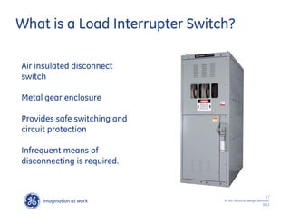
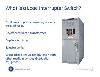
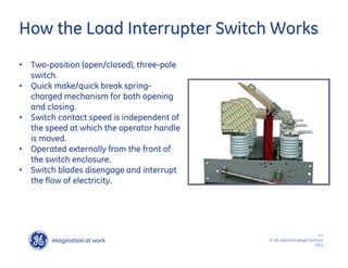
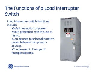
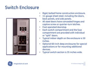
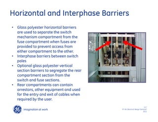
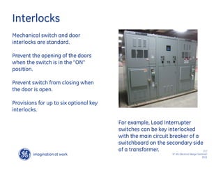
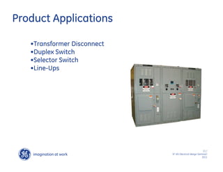
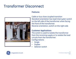
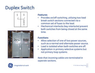
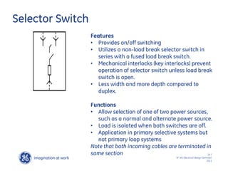
The document discusses load interrupter switches, which are air insulated disconnect switches used in medium voltage distribution systems. They provide safe switching and circuit protection through quick make/quick break mechanisms and fault protection using various types of fuses. Load interrupter switches can be used as transformer disconnects, duplex switches, selector switches, and grouped in lineup configurations with other distribution equipment.
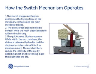


![protection of transmission lines[distance relay protection scheme]](https://cdn.slidesharecdn.com/ss_thumbnails/os-exe3-23-may2011-sr-i-776s21tr-lineprotection-120425095503-phpapp02-thumbnail.jpg?width=640&height=640&fit=bounds)


