Download to read offline
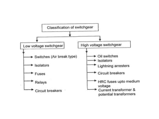
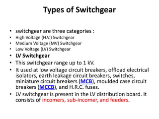

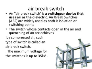
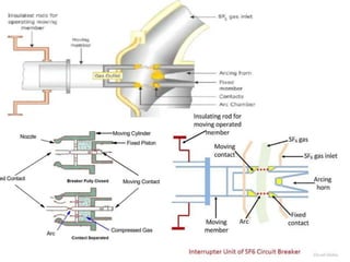
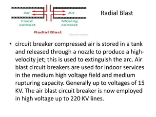
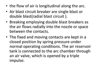
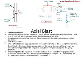
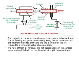
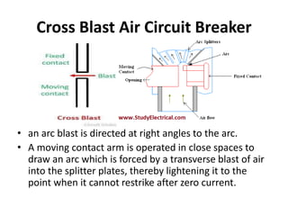

Switchgear is electrical equipment used to control, protect, and isolate electrical systems. It includes components like fuses, switches, relays, and circuit breakers. There are three main types - low voltage, medium voltage, and high voltage. Circuit breakers use various mediums like air, sulfur hexafluoride gas, or oil to detect faults and quickly interrupt current to isolate issues and protect equipment. SF6 gas is commonly used due to its excellent insulating and arc quenching properties. Air blast circuit breakers use compressed air to extinguish arcs by forcing high velocity air jets onto the arc through nozzles.


