IRJET- Modelling, Simulation and Testing of Diesel Engine Water Pump
•
0 likes•56 views

https://www.irjet.net/archives/V6/i6/IRJET-V6I6128.pdf
![International Research Journal of Engineering and Technology (IRJET) e-ISSN: 2395-0056
Volume: 06 Issue: 06 | June 2019 www.irjet.net p-ISSN: 2395-0072
© 2019, IRJET | Impact Factor value: 7.211 | ISO 9001:2008 Certified Journal | Page 572
describe these physical properties. This is Navier-Stokes
Equation and it is the governing equation of CFD. As the
Navier-Stokes Equation is analytical, human canunderstand
it and solve them on a piece of paper. But if we want to solve
this equation by computer, we have to translate it to the
discretized form. The translators are numerical
discretization methods, such as Finite Difference, Finite
Element, Finite Volume methods. Consequently, we also
need to divide our whole problem domain into many small
parts because our discretization is based on them. Then, we
can write programs to solve them.
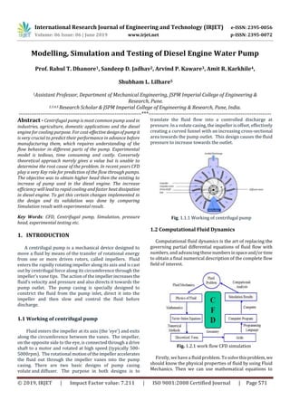
1.2 CFD Analysis Of Centrifugal Pump
CFD simulation makes it possible to visualize the flow
condition inside a centrifugal pump and provide valuable
information about the pump’s hydraulics design. Simulation
results are used to calculate and predict the performance of
a centrifugal pump whichreplacesthelengthyandexpensive
physical experiment of the past. A great deal of work is
saved, in addition to shortening the entire design cycle.
Computational fluid dynamics isbeing progressivelyapplied
in the design of centrifugal pumps. Thus CFD is most
dominant tool for pump designers. The application of CFD
tools is quiet common in industry today. Many tasks can be
solved much faster and cheaper then means of experiments.
With the aid of CFD approach, the complex internal flow
through different component of pump can be studied at the
different operating conditionswhichhelpinimprovement in
the performance at off-design conditions.
Computational fluid dynamics (CFD) is an advanced
computer-based design and analysis technique. A
computational model is designed using CFD. CFD uses
Numerical methods to solve the fundamental nonlinear
differential equations. Computational Fluid Design has
become very popular approach for designing the such
complex geometry. Design can be improved by analyzing
arrangements of multiple geometry using an identical set of
simplification. A better performancecanbeobtainedwiththe
mathematical and computational error and using these
resources in different manners accuracy can be improved
using larger number of elements and due to this techniques
results obtained in a very short time.
2. LITERATURE REVIEW
[1]CFD Analysis of domestic centrifugal pump for
performance enhancement- Satish M Rajmane work to
improve the head of regenerative pump whichisavailablein
the market. The dismantle pump and the geometrical
dimensions were measured using the geometric details the
numerical model was constructed and the CFD analysis was
carried out with ANSYS (Fluent) software thus validate the
numerical model with calculation by analyzing the existing
report recompiled with the analytic solutions.
Boundary conditions used by them are Rotational speed =
2880 rpm, Working fluid = Water, Turbulence model = K-
Omega viscous with turbulence intensity 5%.
They made three modifications to analysis:-
1.Providing additional splitter in Outlet.
2. Increase the no vanes.
3. Inclining the vanes.
He conclude that with each of the modification there is
increase in the head :-
1.By first modification, they found 6 m increase in the
head of the pump.
2. By second modification, they found 7 m increase in the
head of the pump.
3.By third modification, they found 5 m increase in the
head of the pump.
[2]Experimental and CFD Analysis of Centrifugal Pump
Impeller “ A Case Study”-Prof. Kamlesh H. Thakkar analysis
the centrifugal pump usingCFDtechniqueandpredicting the
performance of a mixed flow impellerofcentrifugal pump. In
this paper experimental investigation were conducted on
centrifugal pump with 111 m outlet impeller diameter,
backward curved blades, nominal discharge of 4 liter per
second to assess the impact of various operating condition
like head, discharge, power, and speed on the performance
of pump. Further the impeller is modeled using solid work
software and CFD analysis is carried out using Ansys CFX on
developed model of impeller to predict theperformanceand
verify with the experimental result of pump. After
experiment at various operating condition, the best
operating condition suggested that flow rate 6.25 lps , head
12.49 m, and efficiency of 3.61 % for selected pump.
[3]Md. Abdul Raheem Junaidia , N.B.V Laksmi Kumari ,
Mohd. Abdul Samad , G.M.Sayeed Ahmed-In this research
work the study of fitting the Inner guide vanes at the
entrance of centrifugal fan impeller is to resolve the non-
uniformity of the flow and to get rid of the vortices that are
generated by the existence of Inner distortion. The main
purpose of this work is to evaluate the use of the Inner guide
vanes (IGV) made of sheet metal and fiber reinforced plastic
to improve the fan performance and saving of energy. For
this purpose the ring of blades in radial direction i.e. Radial
cascade, with different exit blade angles of impellers is used.
Comparison with free inner (without IGV)fansisperformed.
Measurement of static head, shaft power and energysavings
at different loads are made for dissimilar cases. The study of
these measurements gives some informationconcerning the
operating range and how energy could be saved in V.A.V.
(variable air volume) system in air conditioning. By using
the above method the overall size of the fan could be
reduced. Hence, after reviewing the available literature,
Inner guide vanes are chosen for the study in the present
research work. Poor efficiency and lack of capacity control
range (which are often found with ageing centrifugal turbo](data:image/gif;base64,R0lGODlhAQABAIAAAAAAAP///yH5BAEAAAAALAAAAAABAAEAAAIBRAA7)
Recommended
Recommended
More Related Content
What's hot
What's hot (19)
Similar to IRJET- Modelling, Simulation and Testing of Diesel Engine Water Pump
Similar to IRJET- Modelling, Simulation and Testing of Diesel Engine Water Pump (20)
More from IRJET Journal
More from IRJET Journal (20)
Recently uploaded
Recently uploaded (20)
IRJET- Modelling, Simulation and Testing of Diesel Engine Water Pump
- 1. International Research Journal of Engineering and Technology (IRJET) e-ISSN: 2395-0056 Volume: 06 Issue: 06 | June 2019 www.irjet.net p-ISSN: 2395-0072 © 2019, IRJET | Impact Factor value: 7.211 | ISO 9001:2008 Certified Journal | Page 571 Modelling, Simulation and Testing of Diesel Engine Water Pump Prof. Rahul T. Dhanore1, Sandeep D. Jadhav2, Arvind P. Kaware3, Amit R. Karkhile4, Shubham L. Lilhare5 1Assistant Professor, Department of Mechanical Engineering, JSPM Imperial College of Engineering & Research, Pune. 2,3,4,5 Research Scholar & JSPM Imperial College of Engineering & Research, Pune, India. ---------------------------------------------------------------------***--------------------------------------------------------------------- Abstract - Centrifugal pump is most common pump used in industries, agriculture, domestic applications and the diesel engine for cooling purpose. For cost-effectivedesignofpumpit is very crucial to predict their performance in advance before manufacturing them, which requires understanding of the flow behavior in different parts of the pump. Experimental model is tedious, time consuming and costly. Conversely theoretical approach merely gives a value but is unable to determine the root cause of the problem. In recent years CFD play a very Key role for prediction of the flow through pumps. The objective was to obtain higher head then the existing to increase of pump used in the diesel engine. The increase efficiency will lead to rapid cooling and faster heatdissipation in diesel engine. To get this certain changes implemented in the design and its validation was done by comparing Simulation result with experimental result. Key Words: CFD, Centrifugal pump, Simulation, pressure head, experimental testing etc. 1. INTRODUCTION A centrifugal pump is a mechanical device designed to move a fluid by means of the transfer of rotational energy from one or more driven rotors, called impellers. Fluid enters the rapidly rotating impeller along its axis and is cast out by centrifugal force along its circumference through the impeller’s vane tips. The action of the impellerincreasesthe fluid’s velocity and pressure and also directs it towards the pump outlet. The pump casing is specially designed to constrict the fluid from the pump inlet, direct it into the impeller and then slow and control the fluid before discharge. 1.1 Working of centrifugal pump Fluid enters the impeller at its axis (the ‘eye’) and exits along the circumference between the vanes. The impeller, on the opposite side to the eye, is connected through a drive shaft to a motor and rotated at high speed (typically 500- 5000rpm). The rotational motionoftheimpelleraccelerates the fluid out through the impeller vanes into the pump casing. There are two basic designs of pump casing volute and diffuser. The purpose in both designs is to translate the fluid flow into a controlled discharge at pressure. In a volute casing, the impeller is offset, effectively creating a curved funnel with an increasing cross-sectional area towards the pump outlet. This design causes the fluid pressure to increase towards the outlet. Fig. 1.1.1 Working of centrifugal pump 1.2 Computational Fluid Dynamics Computational fluid dynamics is the art of replacing the governing partial differential equations of fluid flow with numbers, and advancing thesenumbersinspaceand/ortime to obtain a final numerical description of the complete flow field of interest. Fig. 1.2.1 work flow CFD simulation Firstly, we have a fluid problem. To solvethisproblem,we should know the physical properties of fluid by using Fluid Mechanics. Then we can use mathematical equations to
- 2. International Research Journal of Engineering and Technology (IRJET) e-ISSN: 2395-0056 Volume: 06 Issue: 06 | June 2019 www.irjet.net p-ISSN: 2395-0072 © 2019, IRJET | Impact Factor value: 7.211 | ISO 9001:2008 Certified Journal | Page 572 describe these physical properties. This is Navier-Stokes Equation and it is the governing equation of CFD. As the Navier-Stokes Equation is analytical, human canunderstand it and solve them on a piece of paper. But if we want to solve this equation by computer, we have to translate it to the discretized form. The translators are numerical discretization methods, such as Finite Difference, Finite Element, Finite Volume methods. Consequently, we also need to divide our whole problem domain into many small parts because our discretization is based on them. Then, we can write programs to solve them. 1.2 CFD Analysis Of Centrifugal Pump CFD simulation makes it possible to visualize the flow condition inside a centrifugal pump and provide valuable information about the pump’s hydraulics design. Simulation results are used to calculate and predict the performance of a centrifugal pump whichreplacesthelengthyandexpensive physical experiment of the past. A great deal of work is saved, in addition to shortening the entire design cycle. Computational fluid dynamics isbeing progressivelyapplied in the design of centrifugal pumps. Thus CFD is most dominant tool for pump designers. The application of CFD tools is quiet common in industry today. Many tasks can be solved much faster and cheaper then means of experiments. With the aid of CFD approach, the complex internal flow through different component of pump can be studied at the different operating conditionswhichhelpinimprovement in the performance at off-design conditions. Computational fluid dynamics (CFD) is an advanced computer-based design and analysis technique. A computational model is designed using CFD. CFD uses Numerical methods to solve the fundamental nonlinear differential equations. Computational Fluid Design has become very popular approach for designing the such complex geometry. Design can be improved by analyzing arrangements of multiple geometry using an identical set of simplification. A better performancecanbeobtainedwiththe mathematical and computational error and using these resources in different manners accuracy can be improved using larger number of elements and due to this techniques results obtained in a very short time. 2. LITERATURE REVIEW [1]CFD Analysis of domestic centrifugal pump for performance enhancement- Satish M Rajmane work to improve the head of regenerative pump whichisavailablein the market. The dismantle pump and the geometrical dimensions were measured using the geometric details the numerical model was constructed and the CFD analysis was carried out with ANSYS (Fluent) software thus validate the numerical model with calculation by analyzing the existing report recompiled with the analytic solutions. Boundary conditions used by them are Rotational speed = 2880 rpm, Working fluid = Water, Turbulence model = K- Omega viscous with turbulence intensity 5%. They made three modifications to analysis:- 1.Providing additional splitter in Outlet. 2. Increase the no vanes. 3. Inclining the vanes. He conclude that with each of the modification there is increase in the head :- 1.By first modification, they found 6 m increase in the head of the pump. 2. By second modification, they found 7 m increase in the head of the pump. 3.By third modification, they found 5 m increase in the head of the pump. [2]Experimental and CFD Analysis of Centrifugal Pump Impeller “ A Case Study”-Prof. Kamlesh H. Thakkar analysis the centrifugal pump usingCFDtechniqueandpredicting the performance of a mixed flow impellerofcentrifugal pump. In this paper experimental investigation were conducted on centrifugal pump with 111 m outlet impeller diameter, backward curved blades, nominal discharge of 4 liter per second to assess the impact of various operating condition like head, discharge, power, and speed on the performance of pump. Further the impeller is modeled using solid work software and CFD analysis is carried out using Ansys CFX on developed model of impeller to predict theperformanceand verify with the experimental result of pump. After experiment at various operating condition, the best operating condition suggested that flow rate 6.25 lps , head 12.49 m, and efficiency of 3.61 % for selected pump. [3]Md. Abdul Raheem Junaidia , N.B.V Laksmi Kumari , Mohd. Abdul Samad , G.M.Sayeed Ahmed-In this research work the study of fitting the Inner guide vanes at the entrance of centrifugal fan impeller is to resolve the non- uniformity of the flow and to get rid of the vortices that are generated by the existence of Inner distortion. The main purpose of this work is to evaluate the use of the Inner guide vanes (IGV) made of sheet metal and fiber reinforced plastic to improve the fan performance and saving of energy. For this purpose the ring of blades in radial direction i.e. Radial cascade, with different exit blade angles of impellers is used. Comparison with free inner (without IGV)fansisperformed. Measurement of static head, shaft power and energysavings at different loads are made for dissimilar cases. The study of these measurements gives some informationconcerning the operating range and how energy could be saved in V.A.V. (variable air volume) system in air conditioning. By using the above method the overall size of the fan could be reduced. Hence, after reviewing the available literature, Inner guide vanes are chosen for the study in the present research work. Poor efficiency and lack of capacity control range (which are often found with ageing centrifugal turbo
- 3. International Research Journal of Engineering and Technology (IRJET) e-ISSN: 2395-0056 Volume: 06 Issue: 06 | June 2019 www.irjet.net p-ISSN: 2395-0072 © 2019, IRJET | Impact Factor value: 7.211 | ISO 9001:2008 Certified Journal | Page 573 machines like centrifugal compressor,centrifugal pump, and centrifugal fan) are observed when performance tested in various applications. For this reason, improvement in the stable operating range and reduction in part load power consumptions, particularly in off-design conditions was required. This was achieved byupgradingtheaerodynamics and fitting Inner guide vane control to the machines in this work. [4]M.Lorussoa,T. Capursoa , M. Torresia , B. Fortunatoa, F.Fornarellia,S.M.Camporealea,R.Monterisob-Thispaper provides the reader with guidelines for the definition of coarse but effective meshes on reduced computational domains in order to accurately evaluate the drop curvesand the NPSH3% of centrifugal pumps by means of CFD. The procedure has been validated against experimental data, carried out on single stages ofmulti-stagecentrifugal pumps, and numerical data obtained by a mono-dimensional model. Thanks to the proposed procedure,withoutanydetrimentto the accuracy, a significant computational cost reduction has been experienced with respect to simulations performed on complete stages. 3. AIM & OBJECTIVE To determine the flow around the impeller. To determine the charachterstic of discharge v/s head. To determine the pressure around the volute of the casing. To determine the maximum pressure drop region. To achieve constant V×R Region. 4. MODELLING OF DIESEL ENGINE WATER PUMP COMPONENTS For carrying out 3D CFD simulation of diesel engine water pump the modelling of its parts is required which is done by using the Creo Parametric Version 2.0. Creo Parametric developed by PTC in year 2012isoneofthemost widely used modelling software in various design Firms. Following are the components of diesel engine water pump modelled by Creo Parametric 2.0 are : 4.1 Water Pump Assembly The impeller is mounted on a shaft coupled to driving unit which may be an electric motor or IC Engine. The impeller used is of semi-open type having Radial vanes .The impeller modelled consists of 7 radial vanes. The impeller is used in water pump of diesel engine to increase pressure of the fluid. Fig. 4.1 Isometric view of assembly of pump 4.2 Water Core/ Domain Fig. 4.2 Isometric view of Water core/Domain The above figure shows the solid geometry of the water core present in the volute casing of the centrifugal pump. This water core domain is use for simulation purpose by using the software STAR CCM+. 5. CFD SIMULATION OF CENTRIFUGAL PUMP 5.1 Process of CFD Analysis CFD Simulation of centrifugal pump is carried in three main stages: 1. Pre-processing 2. Solving 3. Post-processing
- 4. International Research Journal of Engineering and Technology (IRJET) e-ISSN: 2395-0056 Volume: 06 Issue: 06 | June 2019 www.irjet.net p-ISSN: 2395-0072 © 2019, IRJET | Impact Factor value: 7.211 | ISO 9001:2008 Certified Journal | Page 574 5.2 Pre Processing Fig.5.2 Water core with Impeller 5.3 Working Parameters Working Parameter Consists of Mesh Modelling, Physics Modelling and defining Boundary Conditions :- 5.3.1 Mesh Modelling – Polyhedral Mesh Volume level Mesh 5.3.2 Physics Modelling - a. K-Epsilon Turbulence. b. Fluid Used – Mixture of water & ethylene glycol with 50% conc. each. 5.3.3 Properties of fluid used - a. Fluid mixture Specific heat – 3.558 KJ/ kg-K. b. Fluid mixture Viscosity – 0.4152 Pascal-sec. c. Fluid mixture Density -1051 kg/m3. 5.3.4 Boundary Conditions - a. Impeller RPM -3000 b. Flowrate LPM at Inlet- 40-70 c. Pressure Outlet (Guage) - 0 Pa. 5.4 Solving Solving of the flow equations requires less time as flow equations are solved iteratively in grid cells. The solution speed is increased by using multicore computer clustersfor calculation purpose. The accurate solutions of the partial differential equations are obtained by converging the results. 5.5 Post-processing Post-processing is the final step in CFD analysis. The various graphs are plotted in this stages. It is used to visualize the results which are obtained from the solver. 5.5.1 Velocity Distribution of Centrifugal pump Impeller (3000 RPM) Fig. 5.5.1 Front View of Velocity Distribution of Centrifugal pump Impeller Figureshows the overall velocity distribution of the impeller when the speed of rotation was set at 3000 RPM. From the observation of above figure the impeller has max. velocity of 22.361 m/s and min. velocity of 0.31691 m/s. 5.5.2 Velocity Distribution in Centrifugal pump Casing Fig. 5.5.2 Front View of Velocity Distribution in Centrifugal pump Casing Figure shows the overall velocity distribution in the pump casing when the speed of rotation wassetat3000RPM.From the observation of above figure the maximum velocity in casing is 21.103 m/s and min. velocity is 0.0094459 m/s. 5.5.3 Pressure Distribution of Centrifugal pump Impeller (3000 RPM) Figure shows the Overall Pressure distribution of the impeller when the speed of rotation was set at 3000 RPM. From the observation of figure the impeller has a max. pressure of 2.4638 bar and min. pressure of 0.051591 bar.
- 5. International Research Journal of Engineering and Technology (IRJET) e-ISSN: 2395-0056 Volume: 06 Issue: 06 | June 2019 www.irjet.net p-ISSN: 2395-0072 © 2019, IRJET | Impact Factor value: 7.211 | ISO 9001:2008 Certified Journal | Page 575 Fig. 5.5.3 Back side View of Pressure Distribution of Centrifugal pump Impeller 5.5.4 Pressure DistributioninCentrifugal pump casing Fig. 5.5.4 Front side View of Pressure Distribution of Centrifugal pump Impeller Figure shows the Overall Pressure distribution in the casing when the speed of rotation wassetat3000RPM.From the observation of figure the impeller has a max. pressure of 2.2000 bar and min. pressure of 0.030584 bar. 5.5.5 Pressure Distribution Evaluation Table indicate the value of head (bar) obtained by varying flow rate (lpm) for the impeller. When the flow rate was 40 lpm, head obtained was 0.7436 bar. And when flow rate increases to 70 lpm the head decreases to 0.58 bar. Therefore we conclude that as the flow rate increases the head obtained decreases gradually. Table 5.5.5 Pressure and the Flow rate properties Flow rate (LPM) CFD Head (bar) 40 0.7436 50 0.7154 60 0.62 70 0.58 Head v/s Flow rate of Impeller Fig. 5.5.5 Plot of head v/s flow rate From the graph we conclude that as the flow rate increases the head decreases gradually. 6. EXPERIMENTAL TESTING OF CENTRIFUGAL PUMP 6.1 Experimental Setup Experimental Setup of Centrifugal Pump consists of Water Pump, Impeller, motor, water storage tank, belt, Pressure sensor. Prime mover motor is connected to the pump by using the belt drive to rotate the impeller. Water storage tank is used to store the water and supply the inlet water as well as collect water from the pump. Inlet and outlet flow rate is measure by using the electro-magnetic flow meter. Inlet and outlet pressure is measured by using the pressure sensor. 6.2 Experimental Procedure Initially the sump tank was filledwithwater.Thewater in the sump tank should be oil free. Motor is connected to pump by using the belt drive. All the outlets were closed and inspection was done to find out if any leakages exist and if so corrections were done to avoid leakages. Then the outlet of pump was opened to remove air bubbles from connecting pipe. Water is then supplied to pump inlet from sump storage by using connecting pipe which has a flow measuring instrument and a pressure sensor. Now the Pump started running.
- 6. International Research Journal of Engineering and Technology (IRJET) e-ISSN: 2395-0056 Volume: 06 Issue: 06 | June 2019 www.irjet.net p-ISSN: 2395-0072 © 2019, IRJET | Impact Factor value: 7.211 | ISO 9001:2008 Certified Journal | Page 576 The water flows through pump towards the cooling arrangement of engine. After that outlet pressure is measured at the outlet of engine by using pressure sensor at the discharge pipe. The water is again recollected into the sump tank and this cycle continues. Image-Experimental Setup 6.3 Experimental Observation By keeping the RPM 3000 We have observe the value of pressure head (bar) by changing the flow rate (LPM). Flow rate (LPM) Experimental Head (bar) 40 0.732 50 0.6912 60 0.63 70 0.5923 TABLE 2 Experimental Observations Head v/s Flow rate of Impeller From the graph we conclude that as the flow rate increases the head decreases gradually. 7. RESULT AND DISCUSSION The impeller geometry was constructed in the CREO Parametric 2.0 and the flow simulationwascarriedoutusing the STAR CCM+. To initialize andrunthesimulation,a hybrid initialization was used to obtain the results. After the analysis was carried out, the results were obtained from the software once the simulation has converged. The simulation iterations were set in 1000 times and all of the simulation results were converged within the range. For the flow simulation, various rotating speeds were selected to be the variable factors in this project. The aim is to come out with an impeller design whichhasa graduallyincreasingpressure distribution in order to be chosen as the most efficient impeller. This study focuses on the pressure distribution of the centrifugal pump impeller by varying the rotation speed at 3000 rpm. The results of the simulations were obtained from the CFD software and compared with the experimental results .The input and output pressures were calculated in order to obtain the pressure head. Graph- Head V/S Flow rate The above plot shows variation of the head w.r.t to flow rate for CFD and Experimental testing. From observation of the curves in the above plot the curves are approximately same with minimum error between CFD and Experimental testing to obtain the desired head. Graph - Error plot
- 7. International Research Journal of Engineering and Technology (IRJET) e-ISSN: 2395-0056 Volume: 06 Issue: 06 | June 2019 www.irjet.net p-ISSN: 2395-0072 © 2019, IRJET | Impact Factor value: 7.211 | ISO 9001:2008 Certified Journal | Page 577 Above plot indicates the error obtained during comparison of the simulation results and the actual experimental testing carried out for the centrifugal pump in diesel engine water pump. 8. CONCLUSIONS Experimental testing wascarriedoutatvarious flow rate conditions and when the obtain results were compared with the results obtained from simulation were approximately same. This comparison validates the accuracy of CFD and experimental approaches. Thus we obtained that the higher head 0.74 bar at the flow rate 40 Lpm. This can be selected for further analysisto improve the performance of pump. References [1] R.Barrio,J. Fernandez b , E. Blancoa , J. Parrondoa Estimation of radial load in centrifugal pumps using computational fluid dynamics. [2] Md. Abdul Raheem Junaidia , N.B.VLaksmi Kumari,Mohd Abdul Samadc, G.M. Sayeed Ahmed CFD Simulation to Enhance the Efficiency of Centrifugal PumpbyApplication of Inner Guide Vanes. [3] M. Lorussoa, T. Capursoa , M. Torresia , B. Fortunatoa , F. Fornarellia , S.M.Camporealea,R.MonterisobEfficientCFD evaluation of the NPSH for centrifugal pumps. [4] Erik Dick, Jan Vierendeels, Sven Serbruyns And John Vande Voorde Performance Prediction Of Centrifugal Pumps With Cfd-tools. BIOGRAPHIES Mr. Rahul T. Dhanore Asst. Professor Department of Mechanical Engineering JSPM’S ICOER, Pune Mr. Shubham L. Lilhare Final Year Student Bachelor of Engineering JSPM’S ICOER, Pune Mr. Sandeep D. Jadhav Final Year Student Bachelor of Engineering JSPM’S ICOER, Pune Mr. Arvind P. Kaware Final Year Student Bachelor of Engineering JSPM’S ICOER, Pune Mr. Amit R. Karkhile Final Year Student Bachelor of Engineering JSPM’S ICOER, Pune