Download to read offline
![International Research Journal of Engineering and Technology (IRJET) e-ISSN: 2395-0056
Volume: 10 Issue: 11 | Nov 2023 www.irjet.net p-ISSN: 2395-0072
© 2023, IRJET | Impact Factor value: 8.226 | ISO 9001:2008 Certified Journal | Page 2
To compare predicted results with actual results
For the successful performance of the pump, hydrauliccomponentsplayanimportant role.Itgivesthe bestperformance
by ratio of outflow to inflow of any pump. The impeller is the most important rotating part of a pump; it imparts energy
to the fluid. The type of impeller design is based on the specific speed of the pump. Refer to Figure 1.1
Figure 1.1-Specific speed and Shape of impeller.
There are a variety of design procedures and methods of calculation. The methods that we have used for the design of
the proto-pump impeller are.
A] As per the guidelines given in the JIS B 8327-2002 standard: Model to Proto scale ratio
B] As per the guidelines given in the Val S Lobanoff pump book
2 Impeller Design As Per- JIS B 8327-2002 standard guidelines:
This standard specifies the method of predicting the performance of a proto pump based on the performanceofa model pump
having approximately the same specific speed. This method is followed whenproven hydraulicsareavailableina model pump.
We have a standard performance curve for the model pump at the required duty parameters, and basedonthesameandusing
the model to proto performance prediction formulas given in the standard JIS-B-8327-2002, we canpredicttheperformance
of the proto pump.
Flow/Discharge Of proto pump : Qp=[Dp/Dm]³ x [Np/Nm] x Qm
Head Of Proto pump : Hp=[Dp/Dm]² x [Np/Nm]² x Hm
Power Of Proto pump : Pp =Pm x [Np/Nm]³ x [Dp/Dm]5
NPSHr of Proto pump : NPSHp =[Dp/Dm] ² x [Np/Nm] ² x NPSHm
Where,
H = Total head of pump in meter
Q = Discharge/Flow of pump in m³/s
P = Shaft power of pump in kW
N = Rotational speed in rpm
D = representative dimension of impeller dia. [mm]
m : model pump , p : proto pump](https://image.slidesharecdn.com/irjet-v10i1101-240111080748-640a44c6/75/Centrifugal-Pump-Impeller-Design-by-Model-to-Proto-Method-and-Its-Performance-Verification-by-Simulation-and-Experimental-Method-2-2048.jpg)


![International Research Journal of Engineering and Technology (IRJET) e-ISSN: 2395-0056
Volume: 10 Issue: 11 | Nov 2023 www.irjet.net p-ISSN: 2395-0072
© 2023, IRJET | Impact Factor value: 8.226 | ISO 9001:2008 Certified Journal | Page 7
The vibrations are slightly higher because of the temporary foundation and clamping arrangements at the test lab.
Table 1.5 - Comparison for specified and actual test results :
Sr. Parameter Specified Observed Remarks
01 Total Head (m) 36.60 36.96 Satisfactory
02 Flow/Discharge (m³/hr) 7945 7953.5 Satisfactory
03 Pump Efficiency (%) 87% 88.09% Satisfactory
04 Noise 87 dBA 82 dBA Acceptable
05 NPSHr, (m) 5.5 5.3
06 Power,P,kW 910.23 908.78
07 Vibrations at Duty
RMS mm/s
-----------------------------
Direction X /Y/Z
As per
ISO10816 Cat-II
Zone B
6.1
4.7 /2.9 / 7.2 Acceptable
Overall performance is satisfactory and well within acceptable limits of the Gr 2B tolerances mentioned in ISO 9906-2012Rot
Dynamic Pumps-Hydraulic Performance Acceptance Tests International Standard.
6. CONCLUSIONS :
The method of ‘Model to Proto Ratio’ is accurate and the best-suited method for the design of pump hydraulic
components when proven hydraulic at the same specific speed is available.
Due to the design of the double suction impeller, the pump requires a low NPSHr as compared to to pump with a
single suction impeller having the same capacity.
The computational fluid dynamics (CFD) analysis technology used is a very useful tool. not only to know the flow
pattern in hydraulic passages but also to predict the hydraulic performance well before building the actual proto.
In comparison to CFD results, a small variation is observed in the experimental results. It is because of
manufacturing variations during the casting and machining stages.
To be cost-competitive, the subject impeller is cast using the sand casting method. Further Improvement in
performance will be achieved if we go for 3D printing casting.
REFERENCES
1] Val S. Lobanoff and Robert R. Ross, “Centrifugal Pumps Design and Application”, Jaico publishing house, (1995), pp
28-44.
2] A.J.Stepanoff, “Centrifugal and Axial Flow Pumps - Theory, Design and Application”, John Wiley and Sons, (1953).pp
90-108.
3] JIS-B-8327-2002: Japanese Industrial Standard for “Testing methods for performance of pump, using model pump”.
4] HI20.3-2010 : Hydraulic Institute standard for “Rotodynamic (Centrifugal and Vertical) pumpEfficiencyPrediction”.
5] BS EN ISO9906: 2012 : Rotodynamic pumps-HydraulicperformanceacceptanceTests-Grade1,1and(ISO9906:2012)](https://image.slidesharecdn.com/irjet-v10i1101-240111080748-640a44c6/75/Centrifugal-Pump-Impeller-Design-by-Model-to-Proto-Method-and-Its-Performance-Verification-by-Simulation-and-Experimental-Method-7-2048.jpg)

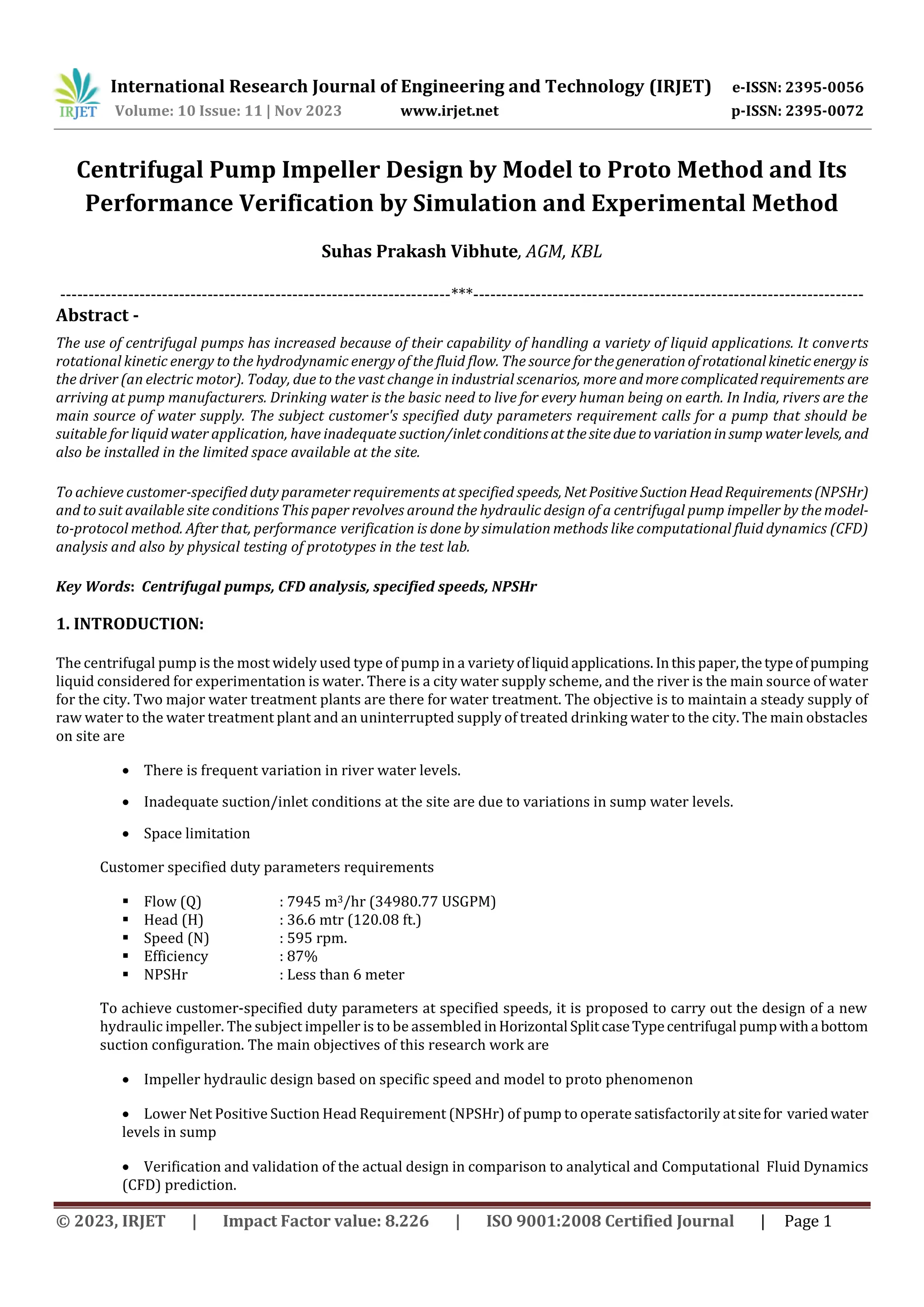
This document discusses the design of a centrifugal pump impeller to meet customer specifications for supplying water to a city. It begins by outlining the project requirements and site constraints. It then describes the impeller design process using two methods: 1) the model-to-proto scale ratio method from standard JIS B 8327-2002 to predict proto pump performance based on a model pump, and 2) guidelines from a pump design book. Computational fluid dynamics analysis is used to verify the impeller design before manufacturing. Experimental testing will then validate the physical performance compared to the design parameters.


