Downloaded 20 times


![Example
Immediate Addressing
MOV R1, #8 ; Reg[R1] 8
ADD R2R2, #3 ; Reg[R2] Reg[R2] + 3
5Budditha Hettige](https://image.slidesharecdn.com/07addressing-170805155812/85/Computer-System-Architecture-Lecture-Note-7-addressing-5-320.jpg)
![Direct Addressing
• Operand is in memory, and is specified by giving
its full address (memory address is hardwired into
instruction)
• Instruction will always access exactly same
memory location, which cannot change
• Can only be used for global variables who
address is known at compile time
• Example Instruction:
– ADD R1, R1(1001) ; Reg[R1] Reg[R1] +Mem[1001]
6Budditha Hettige](https://image.slidesharecdn.com/07addressing-170805155812/85/Computer-System-Architecture-Lecture-Note-7-addressing-6-320.jpg)

![Register Addressing
• Same as direct addressing with the exception that it
specifies a register instead of memory location
• Most common addressing mode on most computers
since register accesses are very fast
• Compilers try to put most commonly accessed
variables in registers
• Cannot be used only in LOAD and STORE instructions
(one operand in is always a memory address)
• Example instruction:
– ADD R3, R4 ; Reg[R3] Reg[R3] + Reg[R4]
8Budditha Hettige](https://image.slidesharecdn.com/07addressing-170805155812/85/Computer-System-Architecture-Lecture-Note-7-addressing-8-320.jpg)
![Register Indirect Addressing
• Operand being specified comes from memory or goes
to memory
• Its address is not hardwired into instruction, but is
contained in a register (pointer)
• Can reference memory without having full memory
address in the instruction
• Different memory words can be used on different
executions of the instruction
• Example instruction:
– ADD R1,R1(R2) ; Reg[R1] Reg[R1] +
Mem[Reg[R2]]
9Budditha Hettige](https://image.slidesharecdn.com/07addressing-170805155812/85/Computer-System-Architecture-Lecture-Note-7-addressing-9-320.jpg)
![Example
• Following generic assembly program calculates the
sum of elements (1024) of an array A of integers of 4
bytes each, and stores result in register R1
– MOV R1, #0 ; sum in R1 (0 initially)
– MOV R2, #A ; Reg[R2] = address of array A
– MOV R3, #A+4096 ; Reg[R3] = address of first word
beyond A
– LOOP: ADD R1, (R2) ; register indirect via R2 to get
operand
– ADD R2, #4 ; increment R2 by one word
– CMP R2, R3 ; is R2 < R3?
– BLT LOOP ; loop if R2 < R3
10Budditha Hettige](https://image.slidesharecdn.com/07addressing-170805155812/85/Computer-System-Architecture-Lecture-Note-7-addressing-10-320.jpg)
![Indexed Addressing
• Memory is addressed by giving a register plus
a constant offset
• Used to access local variables
• Example instruction:
– ADD R3, 100(R2)
; Reg[R3] Reg[R3] + Mem[100+Reg[R2]]
11Budditha Hettige](https://image.slidesharecdn.com/07addressing-170805155812/85/Computer-System-Architecture-Lecture-Note-7-addressing-11-320.jpg)
![Based-Indexed Addressing
• Memory address is computed by adding
up two registers plus an optional offset
• Example instruction:
ADD R3, (R1+R2)
;Reg[R3] Reg[R3] + Mem[Reg[R1] +
Reg[R2]]
12Budditha Hettige](https://image.slidesharecdn.com/07addressing-170805155812/85/Computer-System-Architecture-Lecture-Note-7-addressing-12-320.jpg)
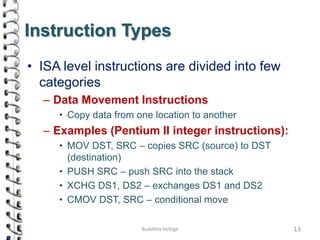

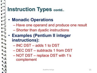


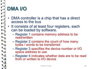


This document discusses various aspects of computer system architecture and instruction types. It describes different addressing modes like immediate, direct, register, register indirect, indexed, and based-indexed addressing. It also explains different types of instructions such as data movement, dyadic operations, monadic operations, comparison/conditional branch, procedure call, loop control, and input/output instructions. Direct memory access (DMA) is described as a method of I/O where a DMA controller facilitates high-speed transfer of data between memory and peripherals without involving the CPU.