This document discusses the basic organization and design of computers. It covers topics such as architecture versus organization, functional units like the arithmetic logic unit and control unit, instruction formats, processor registers, stored program concepts, basic operational concepts like loading and storing data, memory access, and factors that impact performance such as pipelining and instruction set design. The document provides an overview of fundamental computer hardware components and operations.
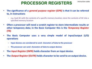
![PROCESSOR REGISTERS
Instruction codes
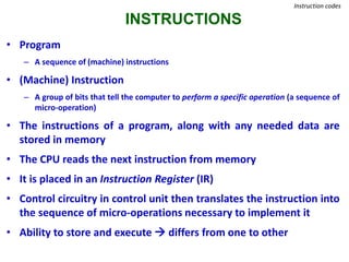
• A processor has many registers to hold instructions, addresses, data, etc….
• The processor has a register, the Program Counter (PC) that holds the
memory address of the next instruction to get
• Control unit stores instruction after reading it from memory is called as
Instruction Register (IR) .
• In a direct or indirect addressing, the processor needs to keep track of what
locations in memory it is addressing: The Address Register (AR) [Same as
MAR] is used for this
• When an operand is found, using either direct or indirect addressing, it is
placed in the Data Register (DR) [same as MDR]. The processor then uses this
value as data for its operation
• The Basic Computer has a Accumulator (AC) for manipulation of data .](https://image.slidesharecdn.com/basicfunctionalunit-190124043726/85/Computer-Organisation-Architecture-chapter-1-9-320.jpg)