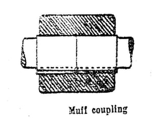
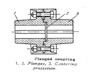
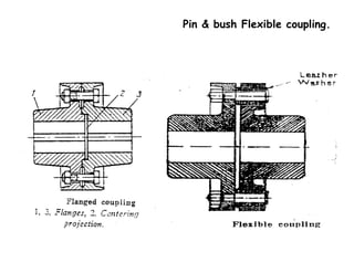
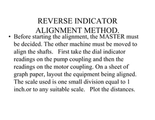
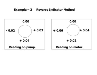
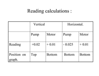
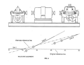
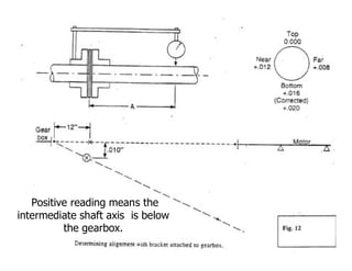
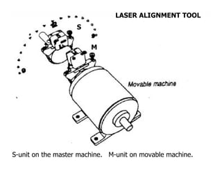
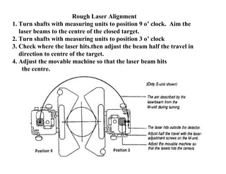
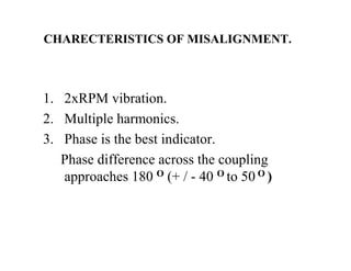
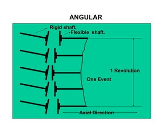
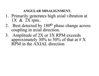
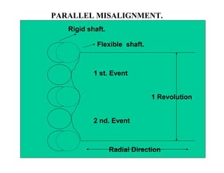
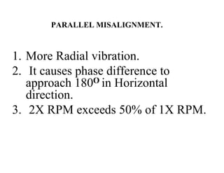
2. COUPLING is the device used to join two shafts
say, the Driver and the Driven to transmit power.
Functions of Shaft Couplings
To provide connection and Dis connection
between the driver & follower.
To provide Alignment facilities.
To allow flexibility between shafts.
To reduce transmission of SHOCK loads.
To introduce protection against overloads.
To alter vibration characteristics of rotating
units.
3. Requirements of a good Shaft Couplings
1. It should be easy to connect and dis-
connect.
2. Should be able to transmit full power.
3. Should hold shaft in alignment.
4. Should be able to reduce the shock
loads.
5. Should have no projecting parts.
6. Should have smooth surfaces.
14. Material for Flexible elements.
• STEEL.
• PLAIN RUBBER.
• SYNTHETIC RUBBER.
• LEATHER.
• TEFLON.
• PLASTIC.
15. a) REMOVAL.
a) Never remove by hammer blow.
b) Use conventional pullers.
c) Hydraulic jack can be used.
d) If needed, removal by heating can
be done, but with great care not to
damage the shaft.
16. b) REFITTING.
a) Clean Shaft surface & Coupling bore.
b) Measure the bore & shaft OD to check tolerance.
c) Do not use a coupling if it has any cracks.
d) Always change coupling in pairs.
e) Check coupling OD for trueness & out of
roundness.
f) If high interference fit is needed, couplings can be
heated in an oil bath up to 120°C.
g) Check Key & Keyway for proper fit.
h) Use pushers for fitting. DO NOT HAMMER.
i) Fit coupling face perpendicular to the shaft axis.
17. PROBLEMS IN COUPLINGS
• Crack on couplings.
• Couplings loose on shaft.
• Holes becoming oval.
• Coupling edge damage.
• Key & Keyway damage.
• Both coupling halves not equal in OD.
18. HYDRAULIC COUPLING
• A hydraulic coupling consists of two identical halves,
one fixed to the driving shaft A and the other to the
driven shaft.B Both these halves are housed in a
common casing, filled with oil.which is used as a
working medium. A is in the form of pump impeller and
B is in the form of a turbine runner.
• When A rotates, oil is forced out through the
periphery of the pump impeller. The oil enters
the turbine runner and makes it to rotate. In
actual practice, the speed of B is less than that of
A by 2 to 4 %
• Efficiency ή = Pb/Pa = Nb/Na
• Slip s = 1 – ή = 1 – Nb/Na
20. Hydraulic Torque Converter
• A hydraulic torque converter is an improved
form of hydraulic coupling. In this, the Torque
( or Speed) of the driven shaft may be increased
o0r decreased. It is achieved by providing a
third member in between the pump impeller
and the turbinr runner, known as guide ring. It
consists of a series of fixed guide vanes, whose
function is to change the direction of oil, which
multiplies the speed of the runner.
21. ALIGNMENT.
Alignment is the adjustment of relative position of
2 coupled machines, so that the centre line of the
axis will be concentric when the machines are
running during NORMAL WORKING
CONDITIONS.
Misalignment may be :-
• PARALLEL.
• ANGULAR.
• COMBINED PARALLEL & ANGULAR.
22.
23. Consequences of misalignment.
• A) Reduction in bearing life.
• B) Coupling degradation.
• C) Shaft fracture.
• D) Vibration.
• E) Other rotating part failures.
25. ALIGNMENT : SOFT FOOT
SOFT FOOT is the condition, when all feet
of the Pump or Motor are not in one plane.
26. ALIGNMENT :
How to Detect SOFT FOOT ?
• Put Machine on base.
• Do not tighten bolts.
• Attempt to pass thin Feeler
Gauge Blade under a Foot.
• If the blade passes, that foot has Soft Foot.
• Check other feet.
27. ALIGNMENT :
How to Rectify SOFT FOOT ?
• Measure Soft foot gap.
• Tighten all hold nuts
• Put Dial Gauge on each foot & loosen the Bolt.
• If foot rises, put Shims.
• Repeat process for each foot.
• Always tighten bolts in one sequence.
28. ALIGNMENT :
SOFT FOOT.
• SOFT FOOT is the condition, when all
feet of the Pump or Motor are not in one
plane or Poor surface contact between
the underside of the Machine or Motor
and the base plate or frame.
29. ALIGNMENT TOLERANCES :
0.013 to 0.0254000 - 6000
0.025 to 0.052000 – 4000
0.05 to 0.101000 – 2000
0.08 to 0.11<1000
TOLERANCE (mm)MACHINE RPM
30. METHODS OF ALIGNMENT :
• Straight Edge, Feeler Gauge & Level.
• Mathematical Method.
• Reverse Indicator Method (graphic)
• Face & Rim Alignment. (graphic)
• Across Flex element. (graphic)
• Laser Beam Method.
40. 500 300
200
ACCURATE ALIGNMENT CALCULATION :
4.5
4.0
Coupling Gap Top= 4.5 mm. Coupling to Front Foot = 500 mm
Coupling Gap Bottom=4.0 mm. Front to Back Foot = 300 mm
Coupling Radius = 200/2= 100 mm. Total distance = 800 mm
41. Alignment calculations
Gap difference = 4.5 – 4 = 0.5 / 2 = 0.25 (A)
a) Distance corrections = 800 / 100 = 8 (B)
So (A) x (B)=0.25 x 8 = 2 mm shim is to be
given under each back foot.
b) Corrections when front feet are to be raised :-
Distance corrections = 500 / 100 = 5 (B)
So (A) x(B) =0.25 x 5 = 1.25 mm shim is to be
given under each front foot.
42. REVERSE INDICATOR
ALIGNMENT METHOD.
• Before starting the alignment, the MASTER must
be decided. The other machine must be moved to
align the shafts. First take the dial indicator
readings on the pump coupling and then the
readings on the motor coupling. On a sheet of
graph paper, layout the equipment being aligned.
The scale used is one small division equal to 1
inch.or to any suitable scale. Plot the distances.
48. Reading calculations :
Pump Motor
Horizontal.
Near + 0.006
Far (-) +0.004 (-)
+0.002 /2 =
Horizontal.
Near - 0.005
Far (-) - 0.015 (+)
+0.010 /2 =
Vertical.
+ 0.005
- 0.000
+ 0.005
Sag (-)- 0.005 (+)
+ 0.010/2 =
Vertical.
- 0.025
- 0.000
- 0.025
Sag (-)-0.005 (+)
- 0.020 / 2 = - 0.010 + 0.005
+ 0.005 + 0.001
49. Pump to motor alignment guide.
- Near side + Near side- on bottom + on bottom
+ Near side - Near side+ on bottom - on bottom
- Near side - Near side- on bottom - on bottom
+ Near side + Near side+ on bottom + on bottom
Reading on motorReading on pumpReading on motorReading on pump
Horizontal (Top view)Vertical (Side view)
Pump shaft Motor shaft
55. P M FF BF
0.125
P M FF BF
0.01 0.0455
Vertical correction
Horizontal correction
0.05
(Scale 1=0.005)
Distance : P M=130 mm; M FF=180 mm; FF BF= 330 mm.
Scale 1= 100 mm
TOP
BOTTOM
FAR
NEAR
56. Conclusion :
Top – Bottom correction :
• The motor shaft : 0.05 shim is to be given
under each front foot and 0.125 shim under
each back foot
Far – Near correction :
• The motor shaft has to be shifted towards
near end. The front feet by 0.01 and the
back feet by 0.0455
57. MULTIUNIT ALIGNMENT
• Plot all three units in a single piece of graph
paper using the reverse indicator method.
Unit 1 is master, there will be two lines for
unit 2 and unit 3. Draw an alternate
reference line close to the actual position of
the three units. Minimal movement is
required to get all units aligned.
64. Rough Laser Alignment
1. Turn shafts with measuring units to position 9 o’ clock. Aim the
laser beams to the centre of the closed target.
2. Turn shafts with measuring units to position 3 o’ clock
3. Check where the laser hits.then adjust the beam half the travel in
direction to centre of the target.
4. Adjust the movable machine so that the laser beam hits
the centre.
65.
66. Alignment and its effect on vibration.
• Misalignment causes vibration.
• There is no 1 to 1 relation with amount of
misalignment and amount of vibration.
• Misalignment can cause failure of not only the
coupling but also Bearings and other moving
parts.
• Highest reaction is on the free or outboard
bearing instead of inboard end.
• Misalignment normally causes both Axial and
Radial vibration.
67. OTHER SOURCES OF HIGH AXIAL VIBRATION.
• Bent shafts.
• Shaft in resonant whirl.
• Resonance of some components in axial direction.
• Worn thrust bearing.
• Worn helical and bevel gears.
• A sleeve bearing motor hunting for its magnetic
centre.
• Couple component of dynamic unbalance.
(So high axial vibration should not be concluded as the
problem of misalignment only)
68. CHARECTERISTICS OF MISALIGNMENT.
1. 2xRPM vibration.
2. Multiple harmonics.
3. Phase is the best indicator.
Phase difference across the coupling
approaches 180 O (+ / - 40 O to 50 O )
70. ANGULAR MISALIGNMENT.
1. Primarily generates high axial vibration at
1X & 2X rpm..
2. Best detected by 180O phase change across
coupling in axial direction.
3. Amplitude of 2X or 3X RPM exceeds
approximately 30% to 50% of that at # X
RPM in the AXIAL direction
72. PARALLEL MISALIGNMENT.
1. More Radial vibration.
2. It causes phase difference to
approach 180O in Horizontal
direction.
3. 2X RPM exceeds 50% of 1X RPM.
73. MISALIGNED BEARING COCKED IN SHAFT..
1. A cocked bearing will normally generate
considerable axial vibration which affects 1X
RPM & 2X RPM.
2. If phase is measured in the axial direction at
each of a 4 points 90O apart from each other
a cocked bearing will be indicated by 180O
phase shift from top to bottomj and side to
side.
74. COUPLING PROBLEMS
1. 2X RPM will often respond to
coupling problems.
2. In these cases both Radial and Axial
direction will show a fairly
noticeable 3X RPM component.
75. Thank you !
Any questions please ?
Presented by :
A. Jayprakash