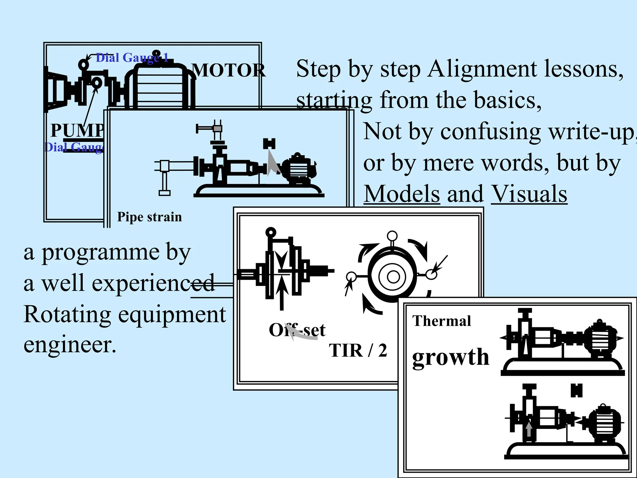
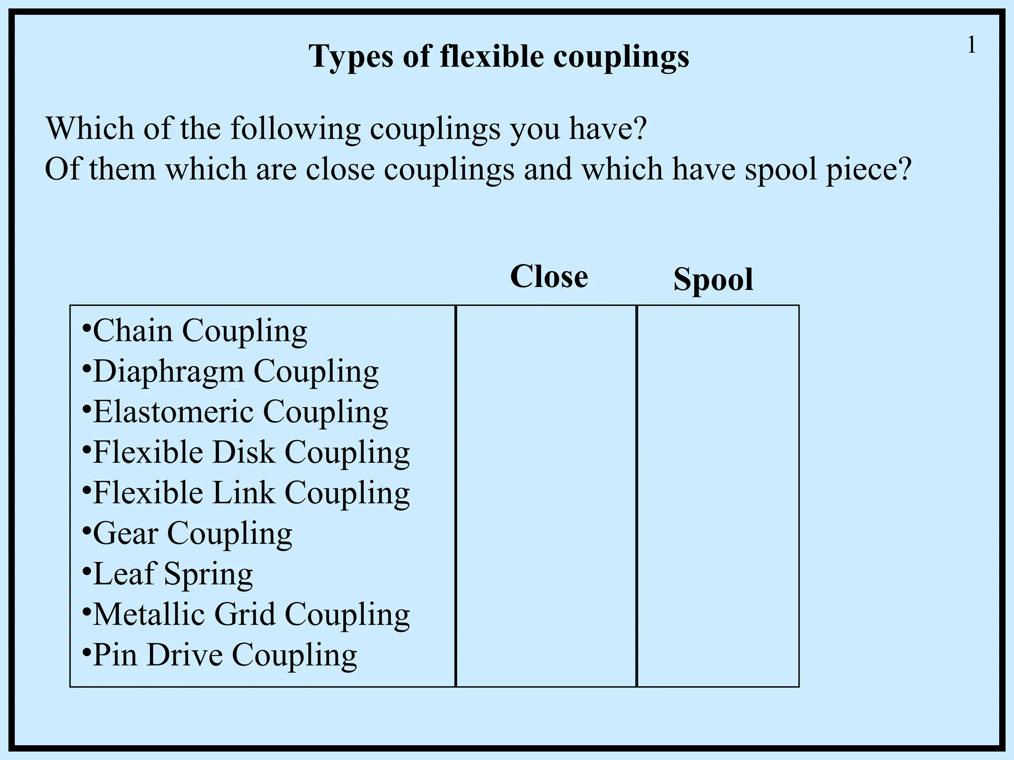
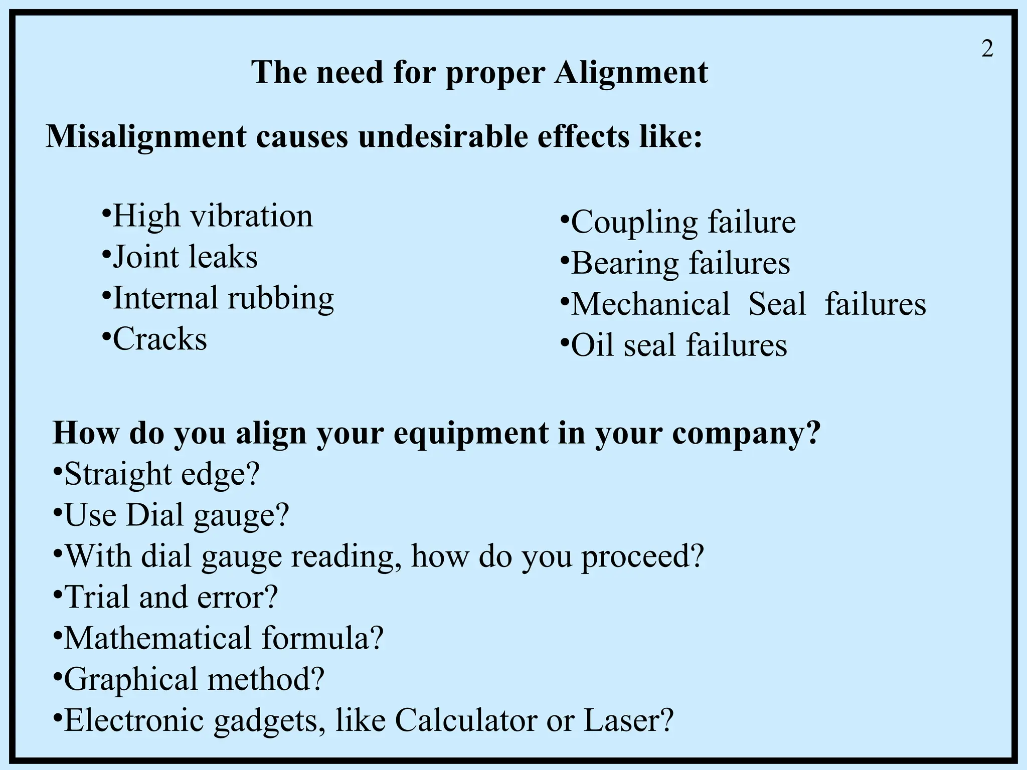
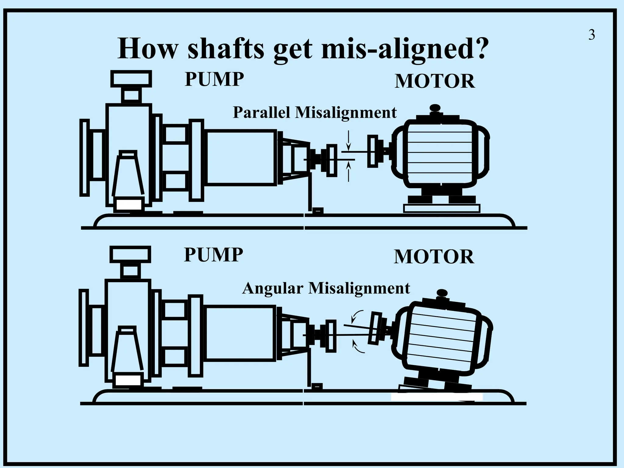
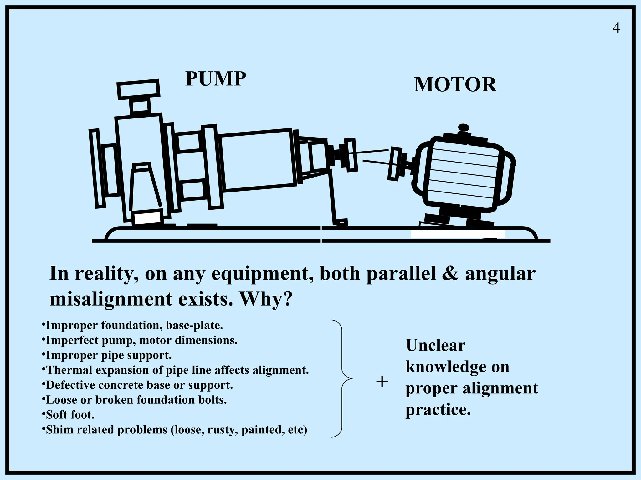
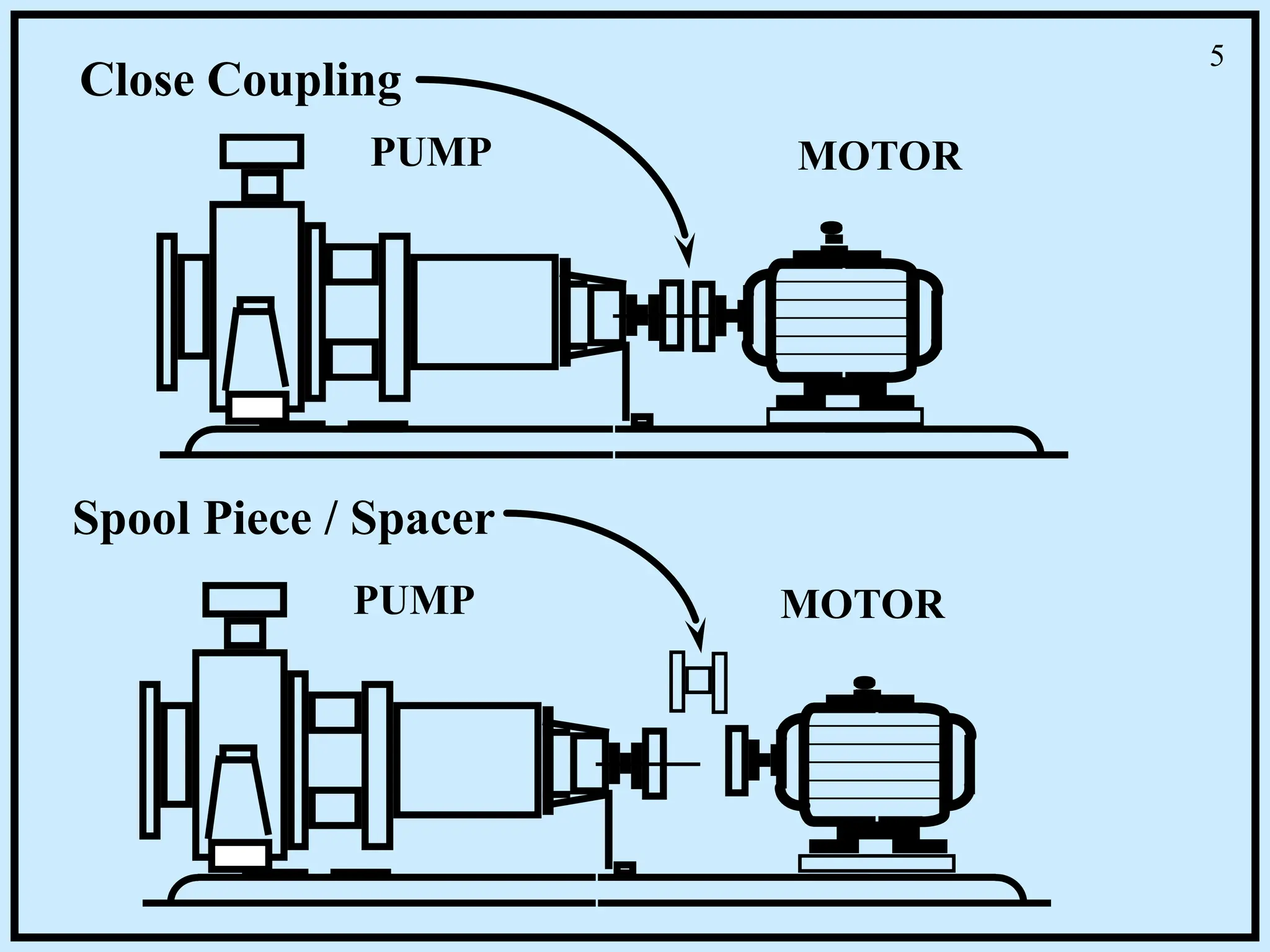
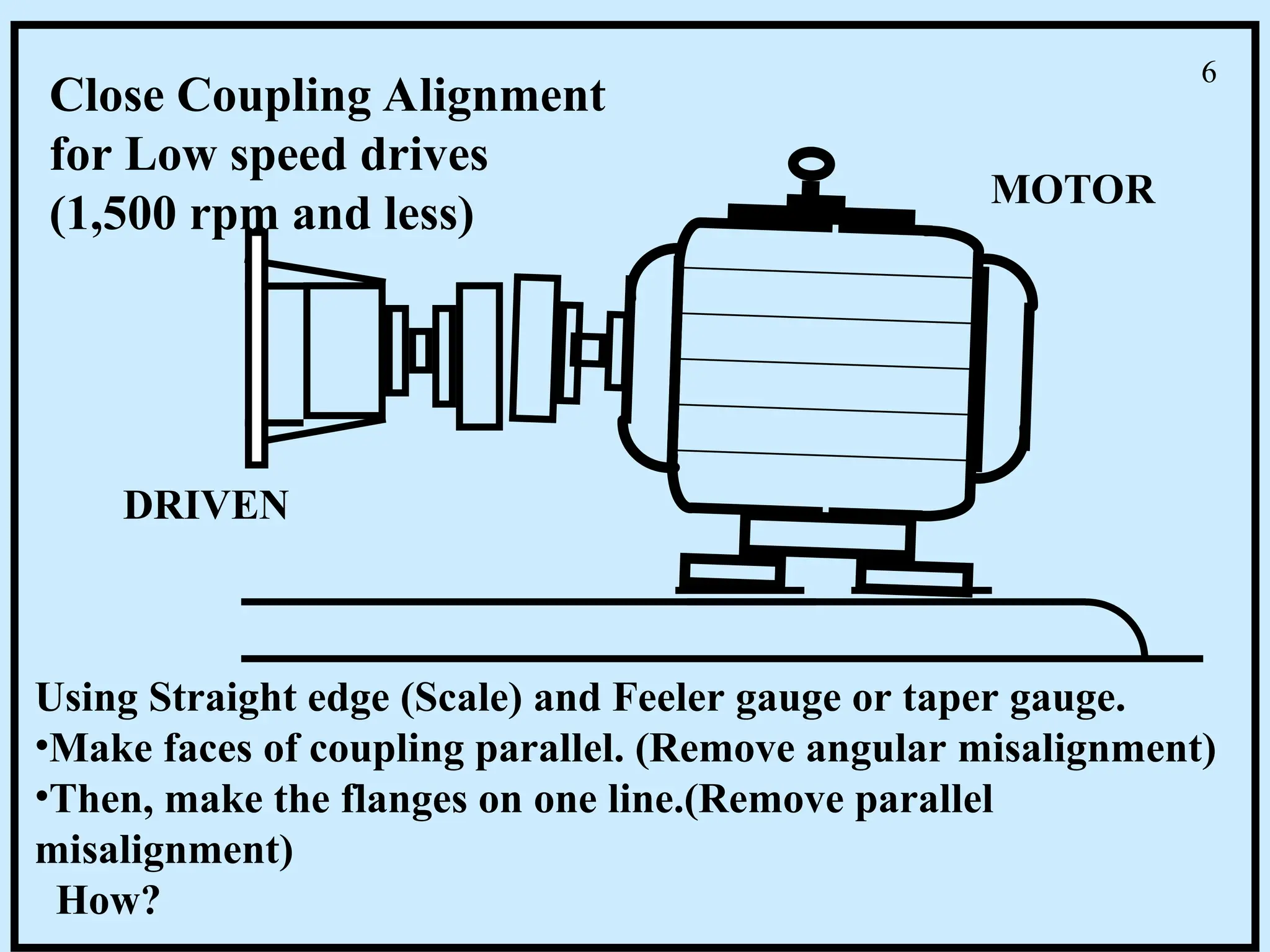
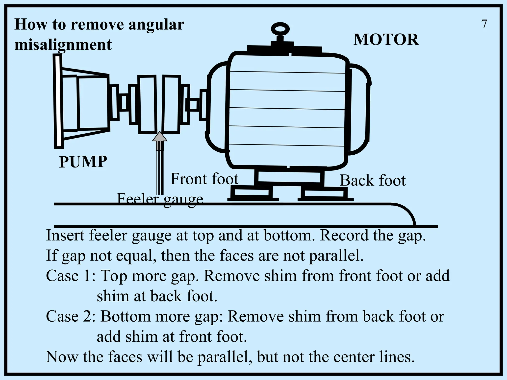
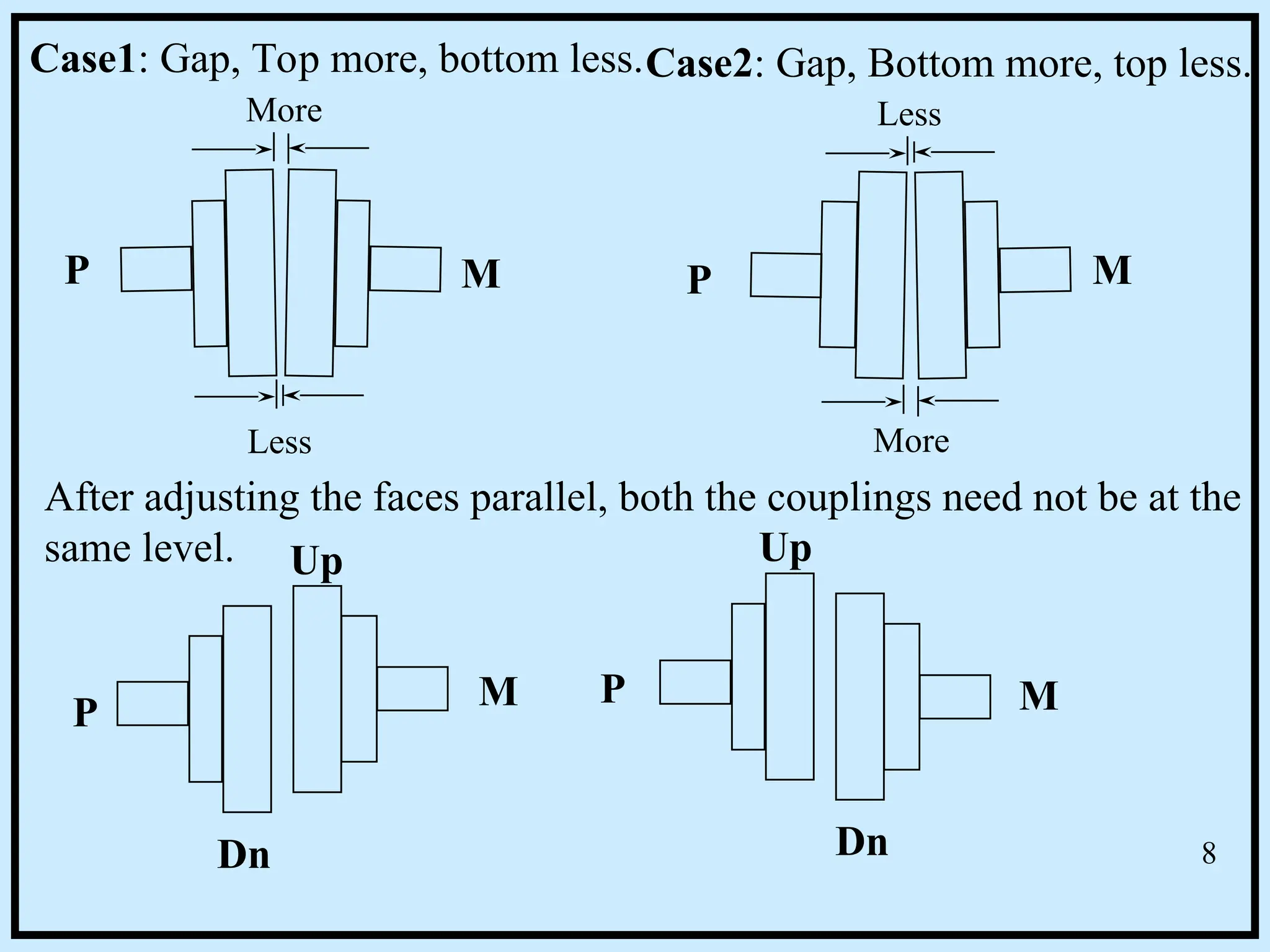
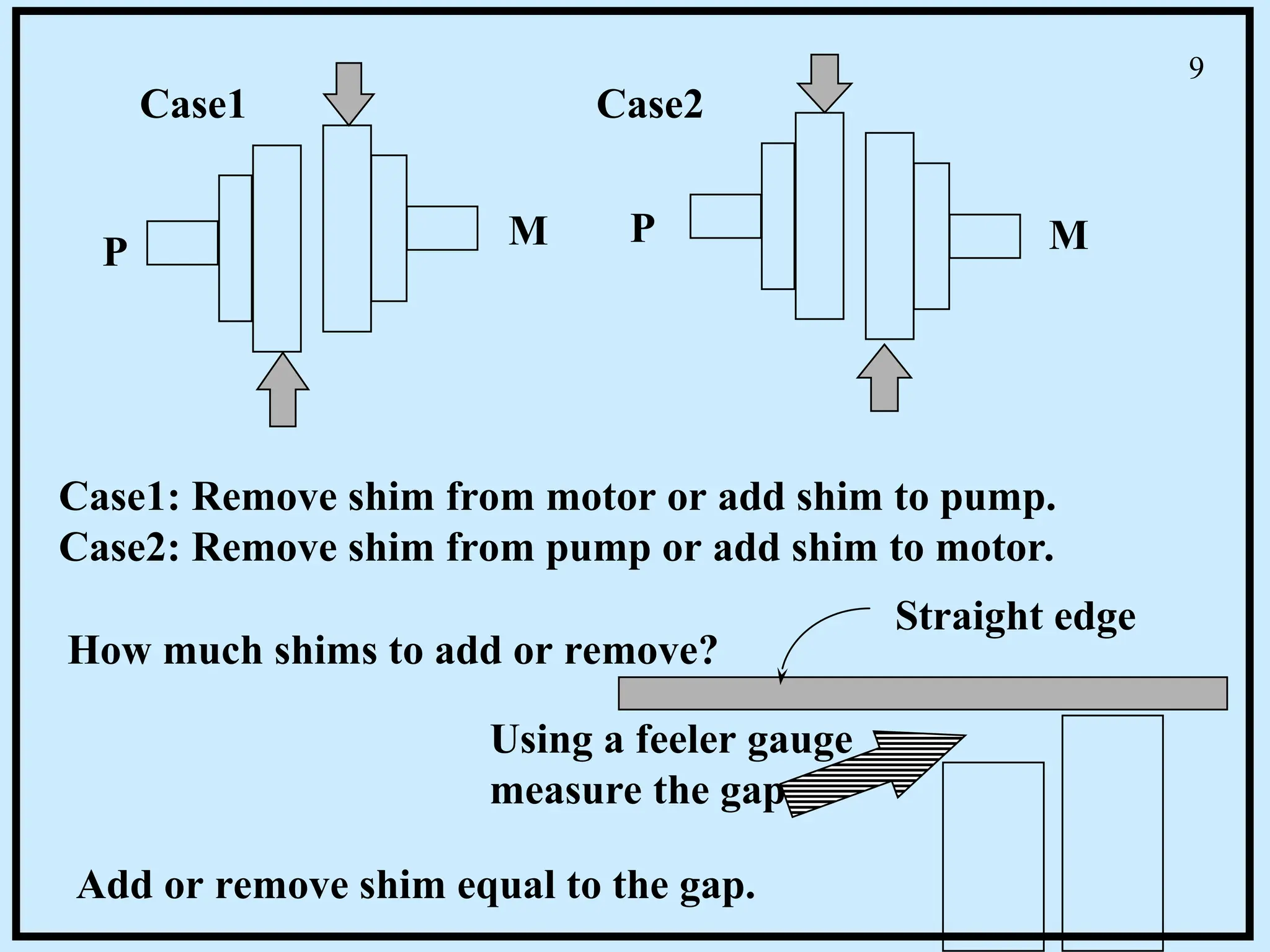
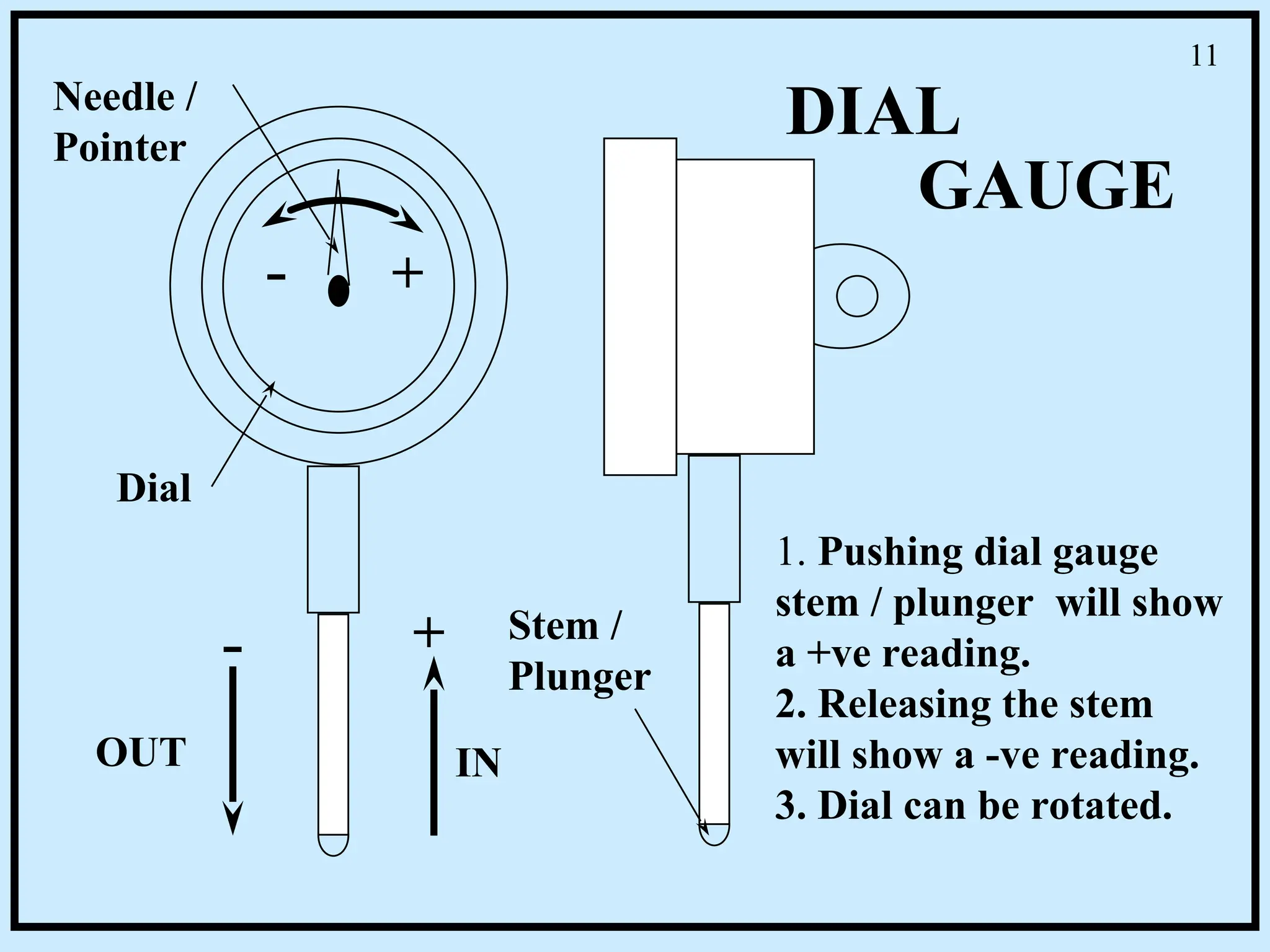
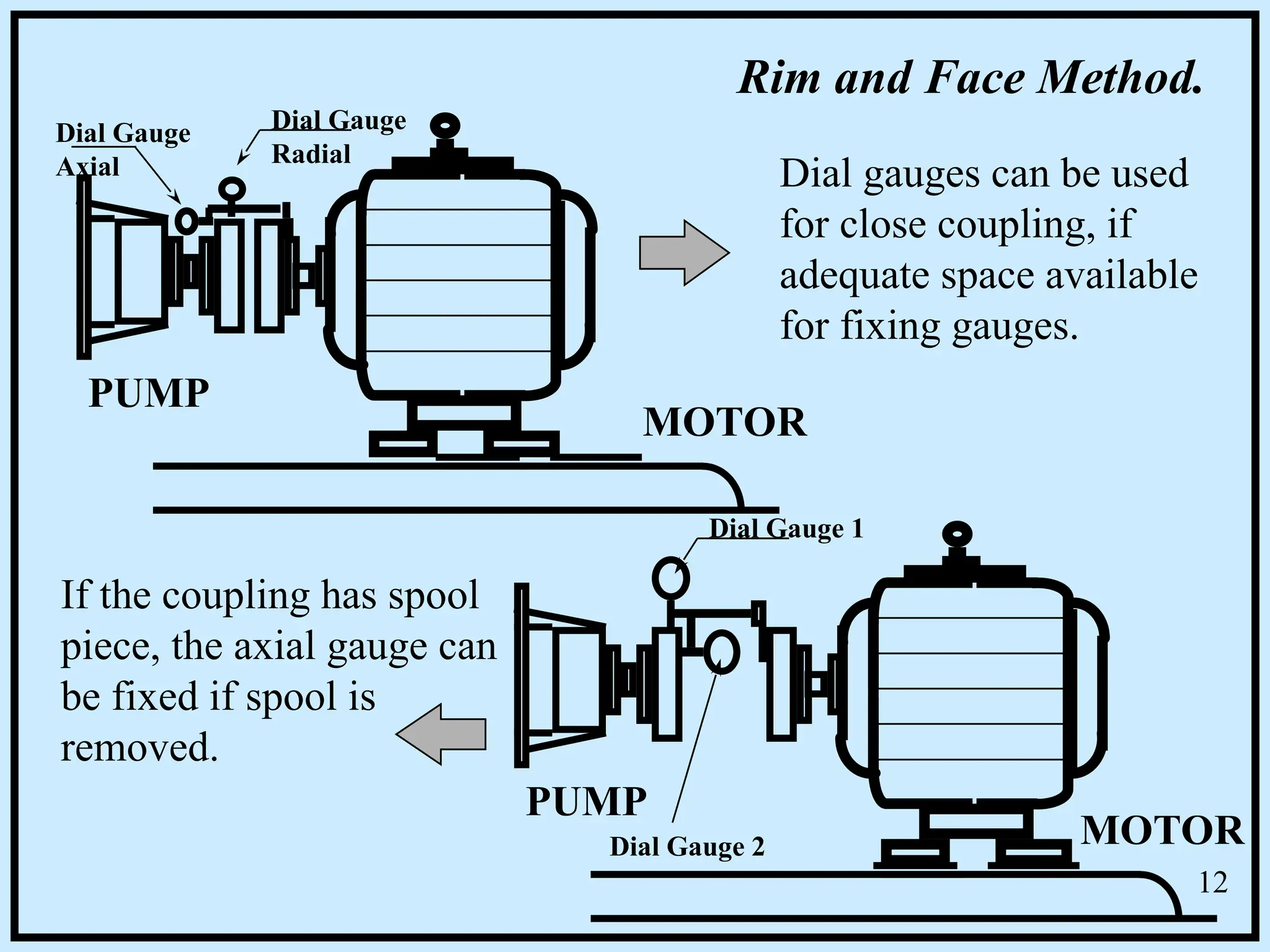
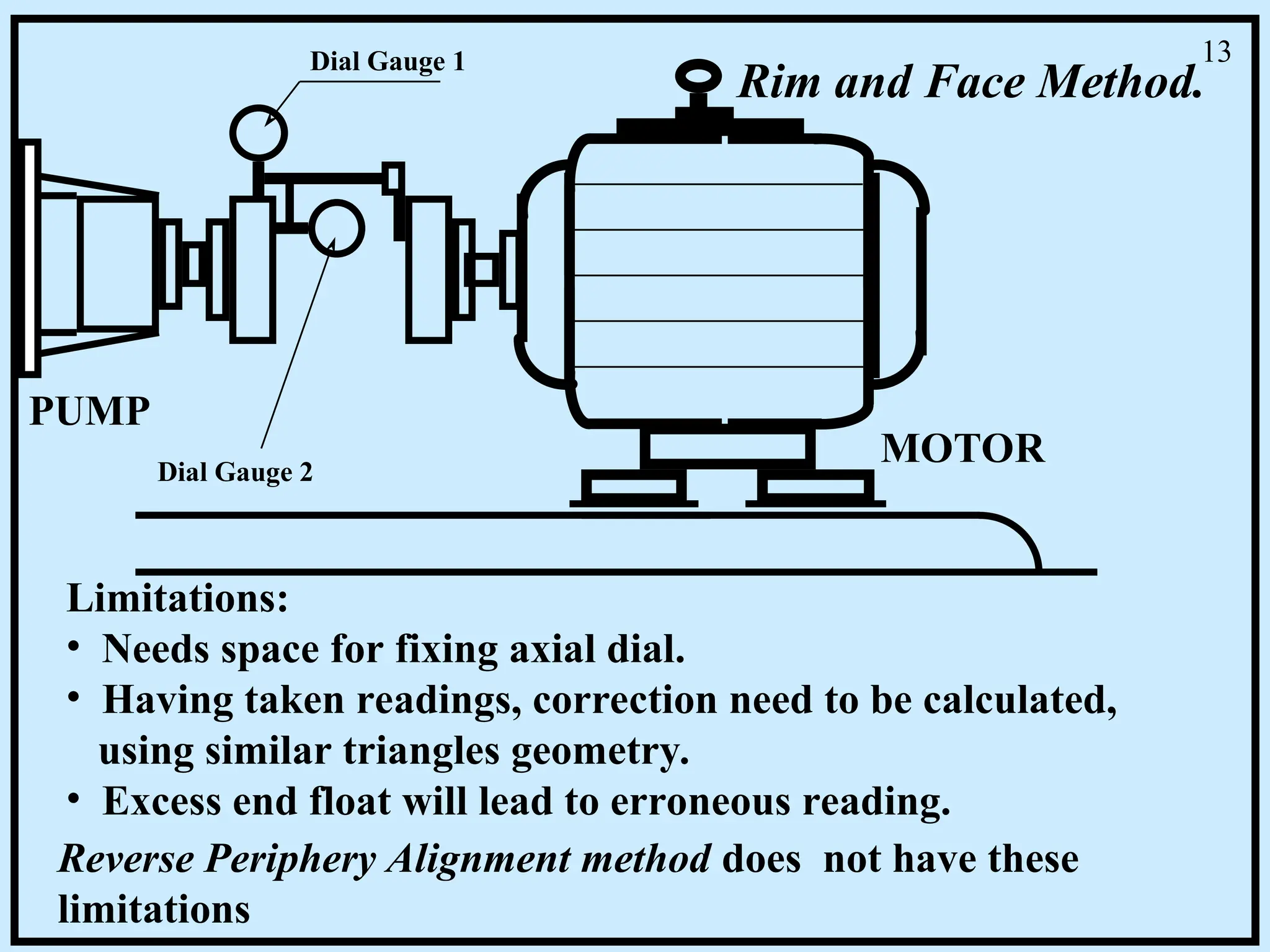
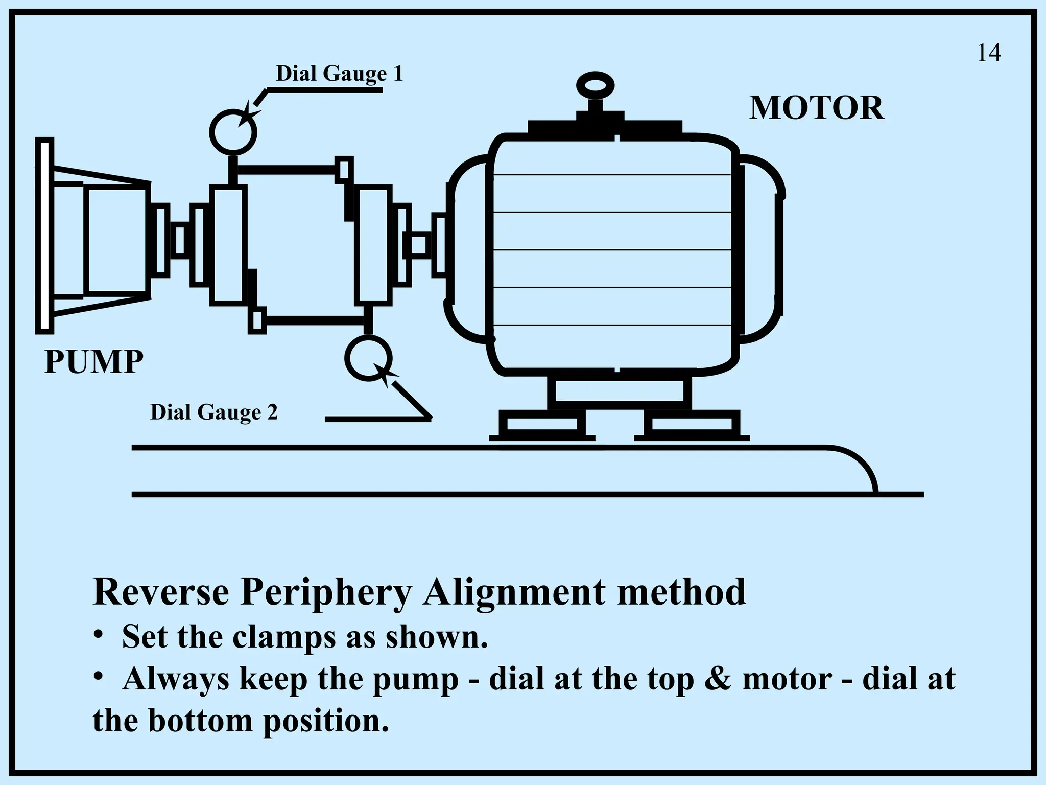
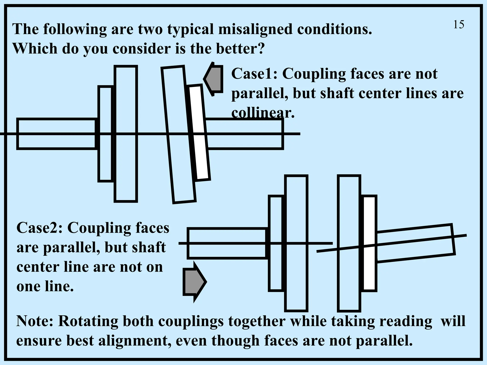
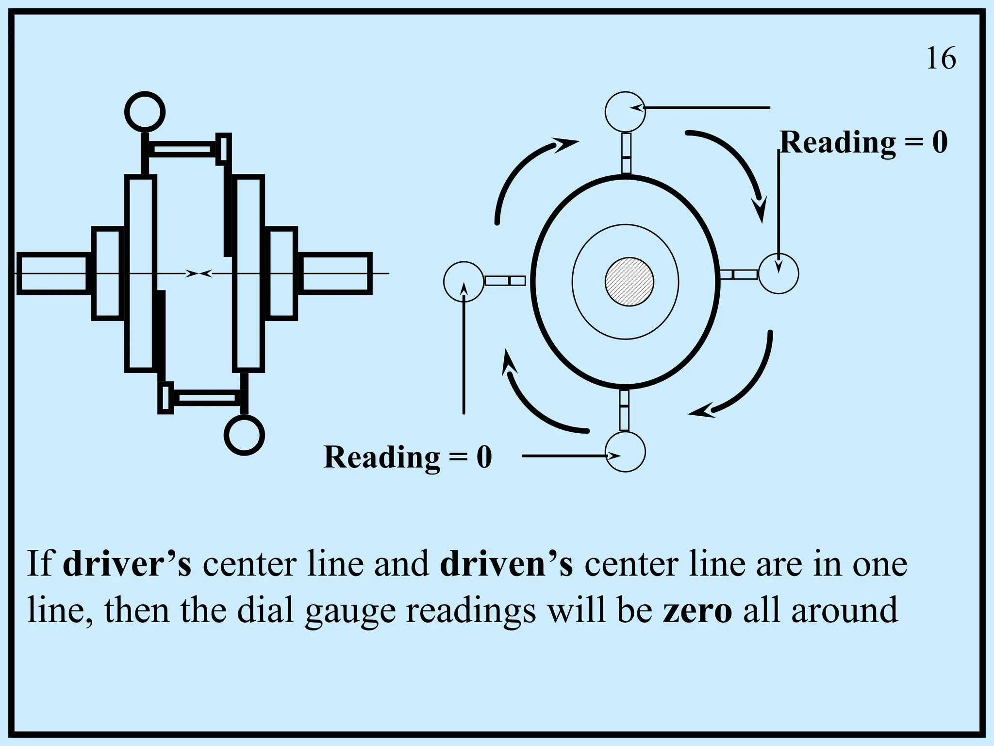
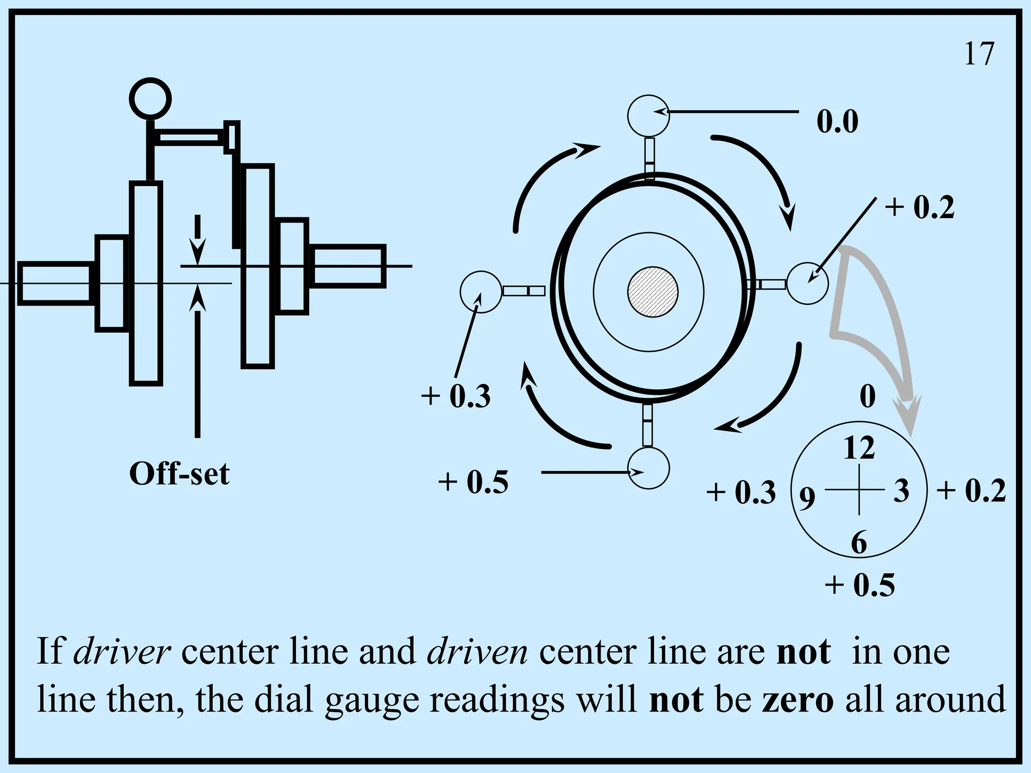
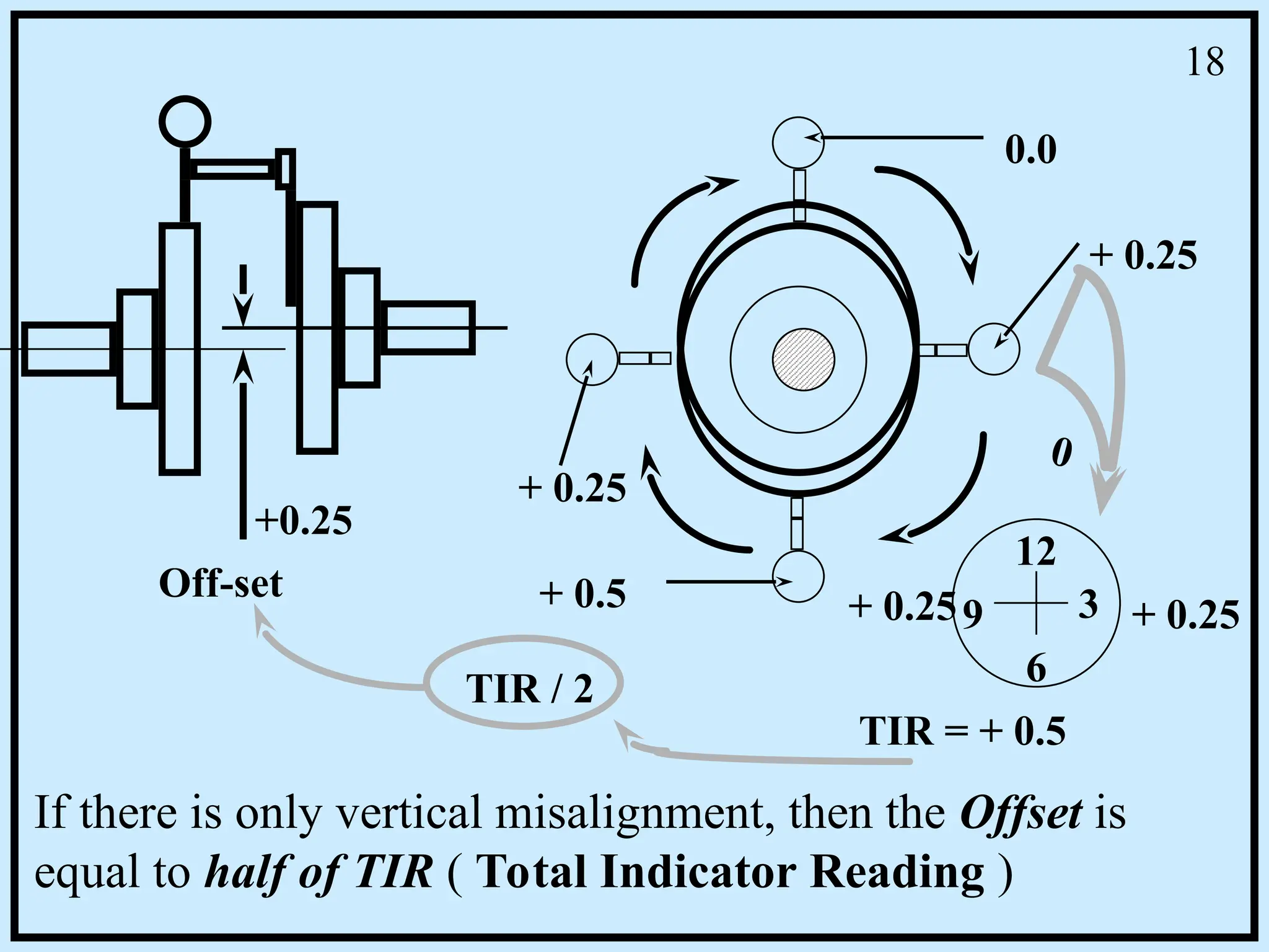
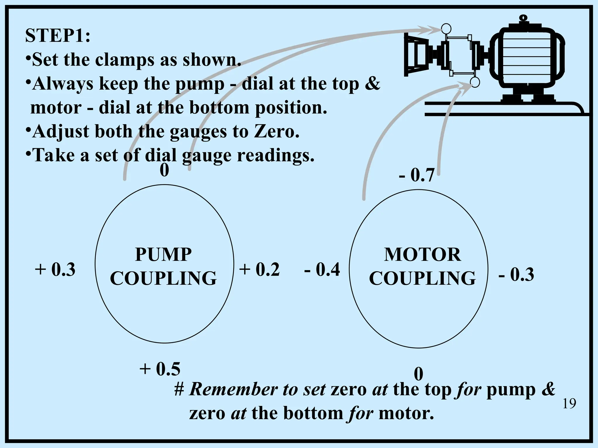
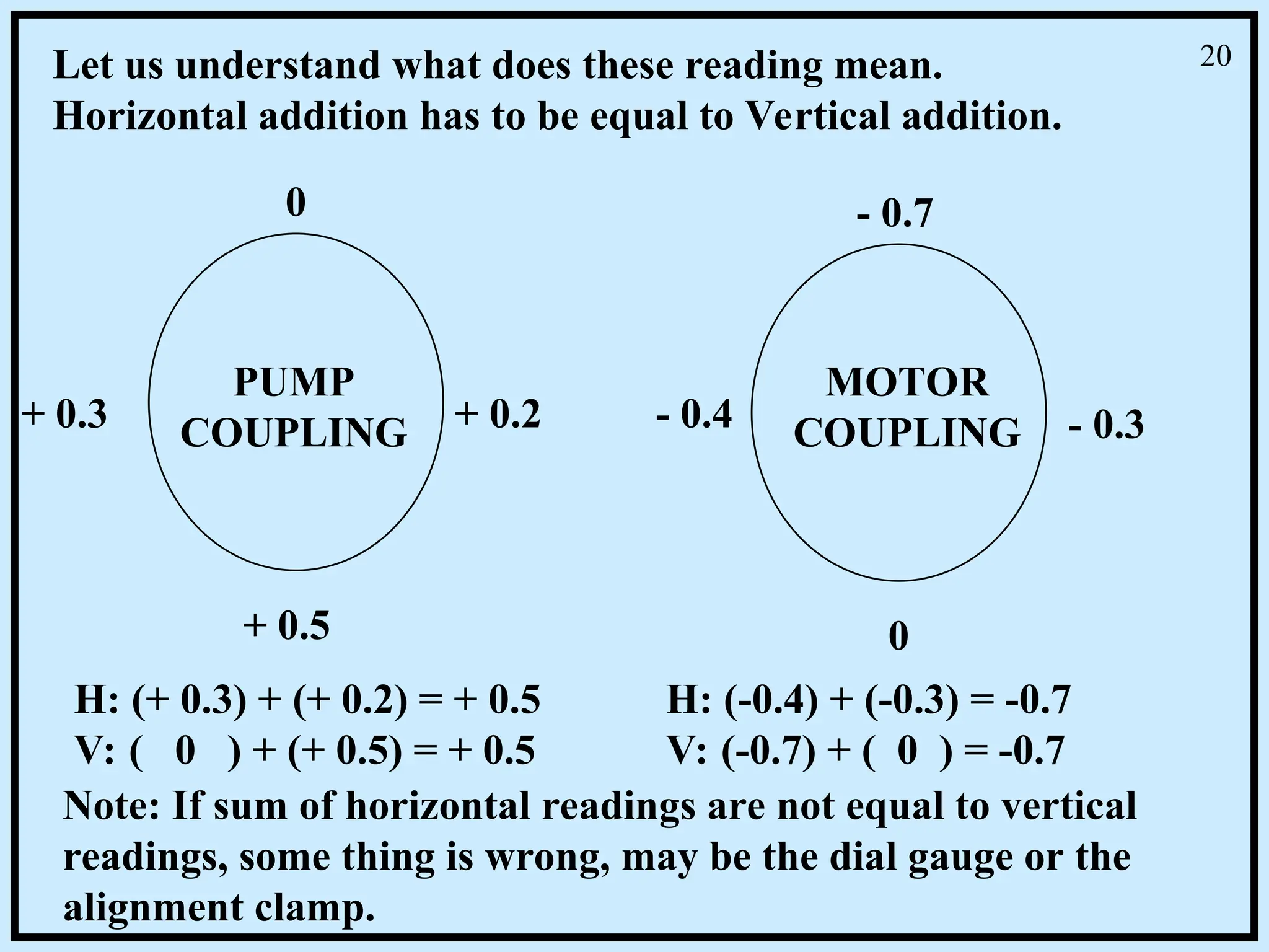
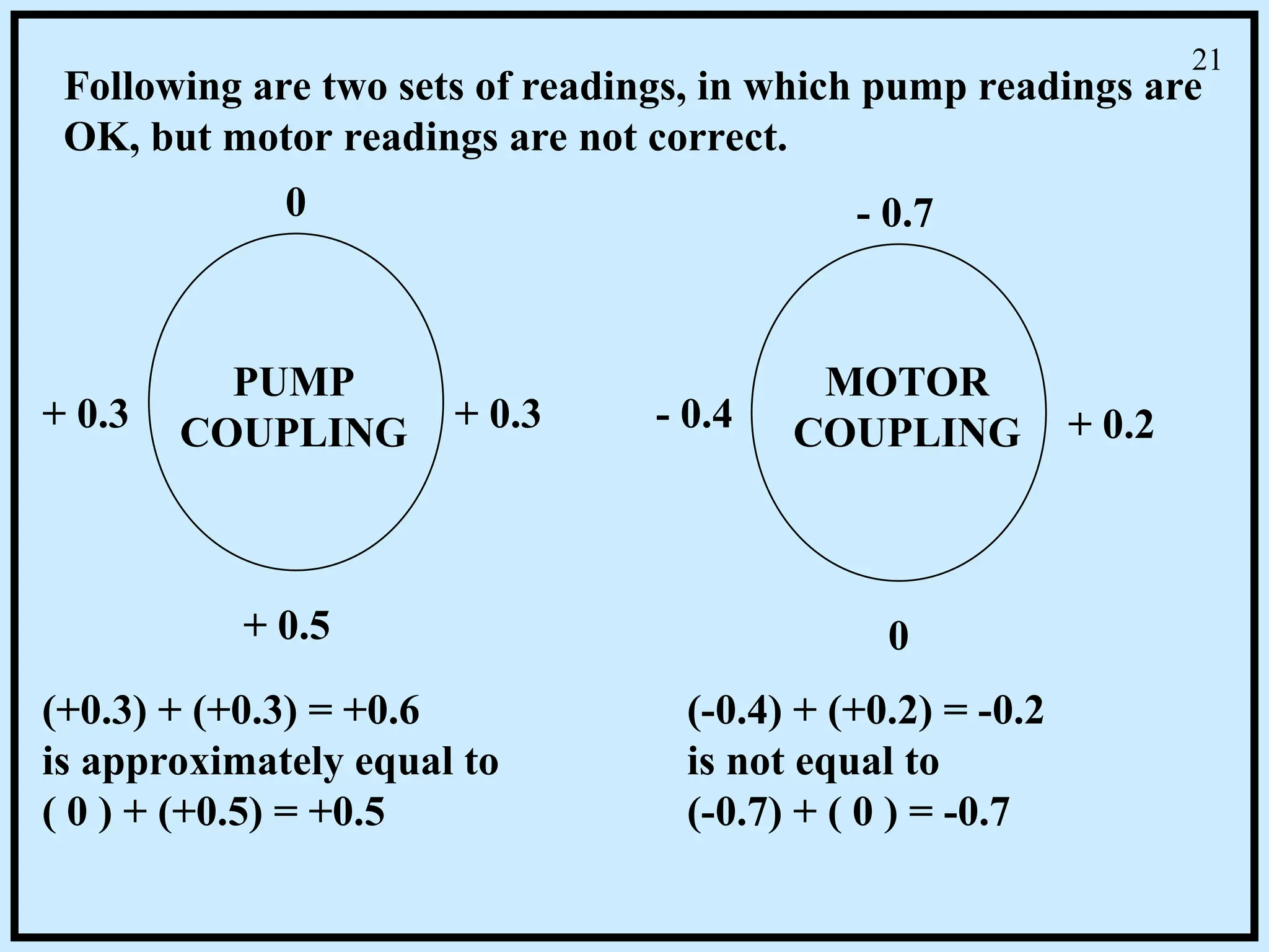
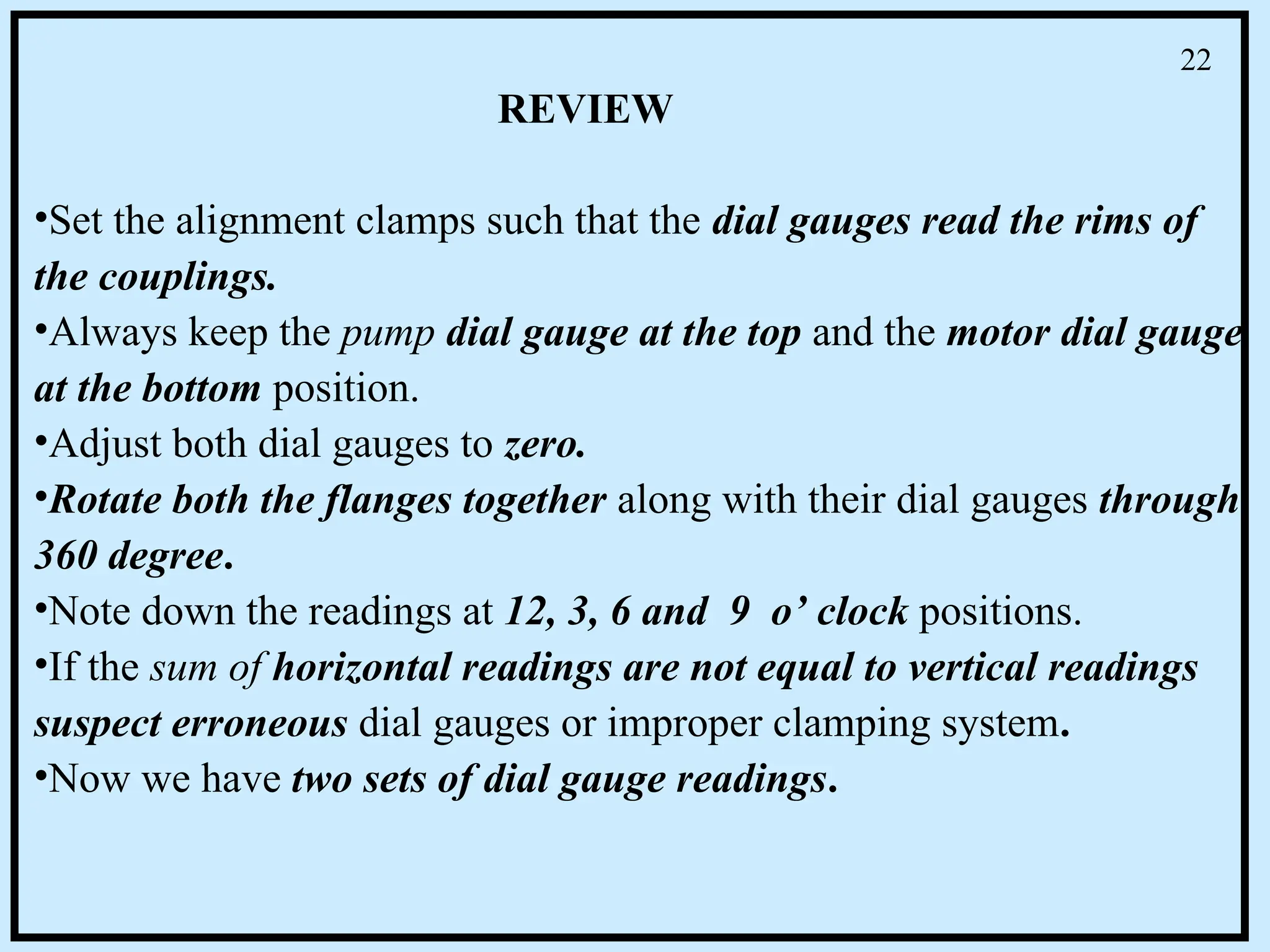
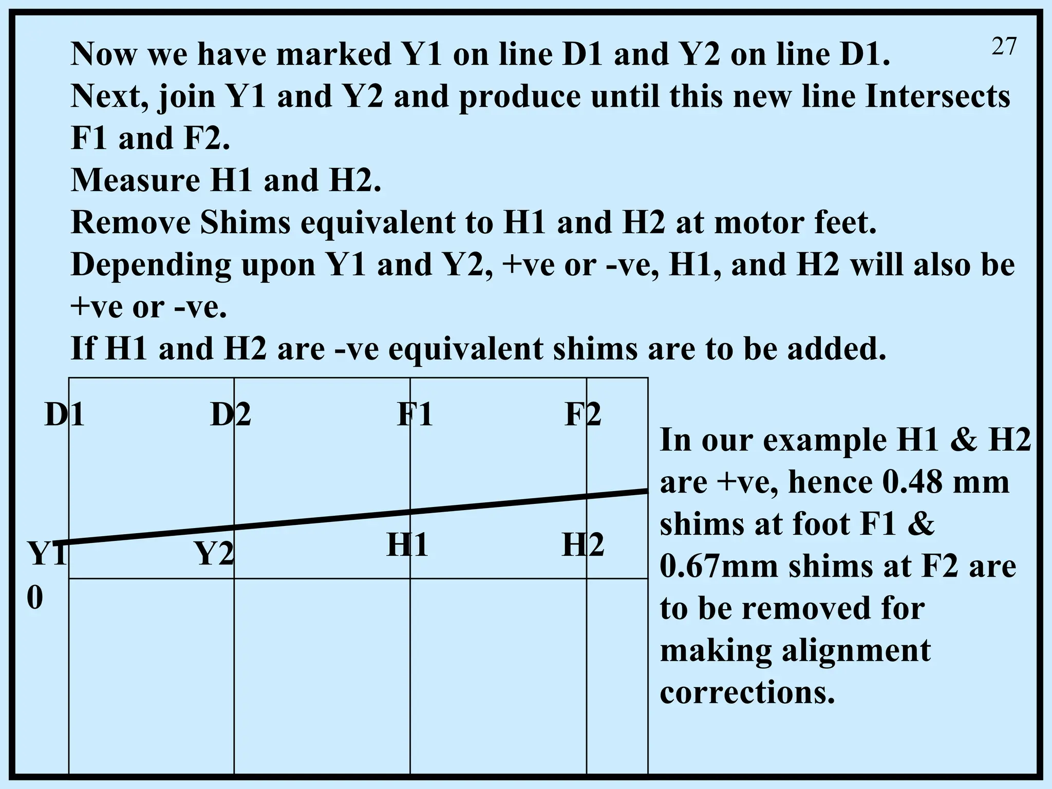
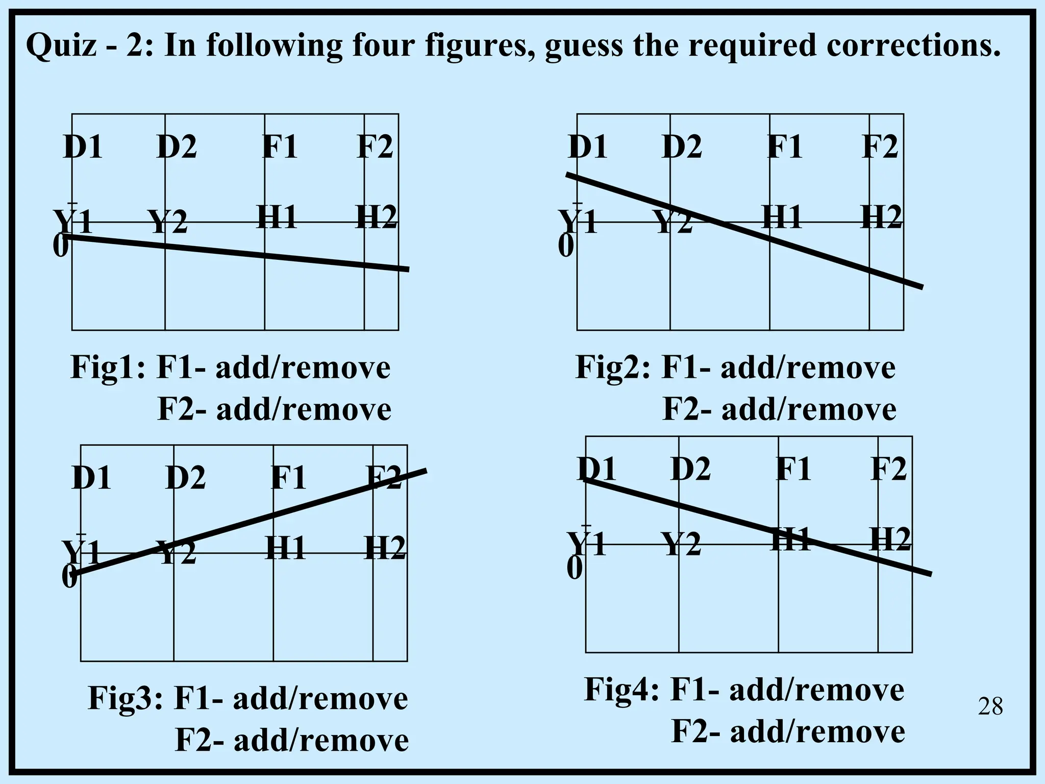
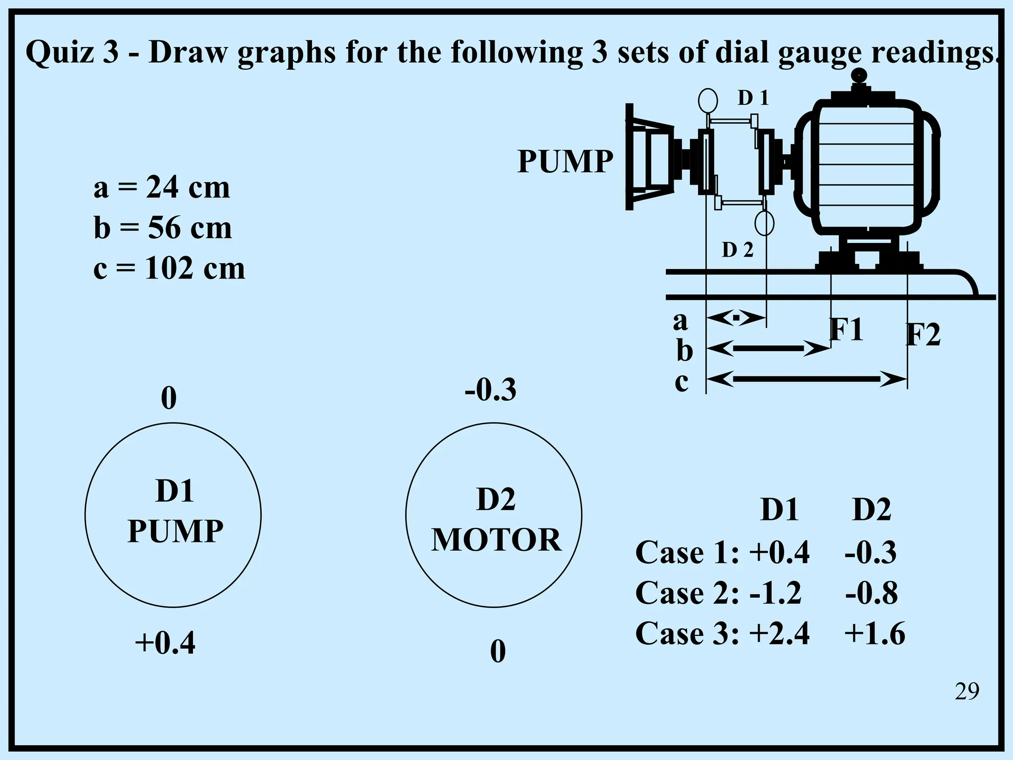
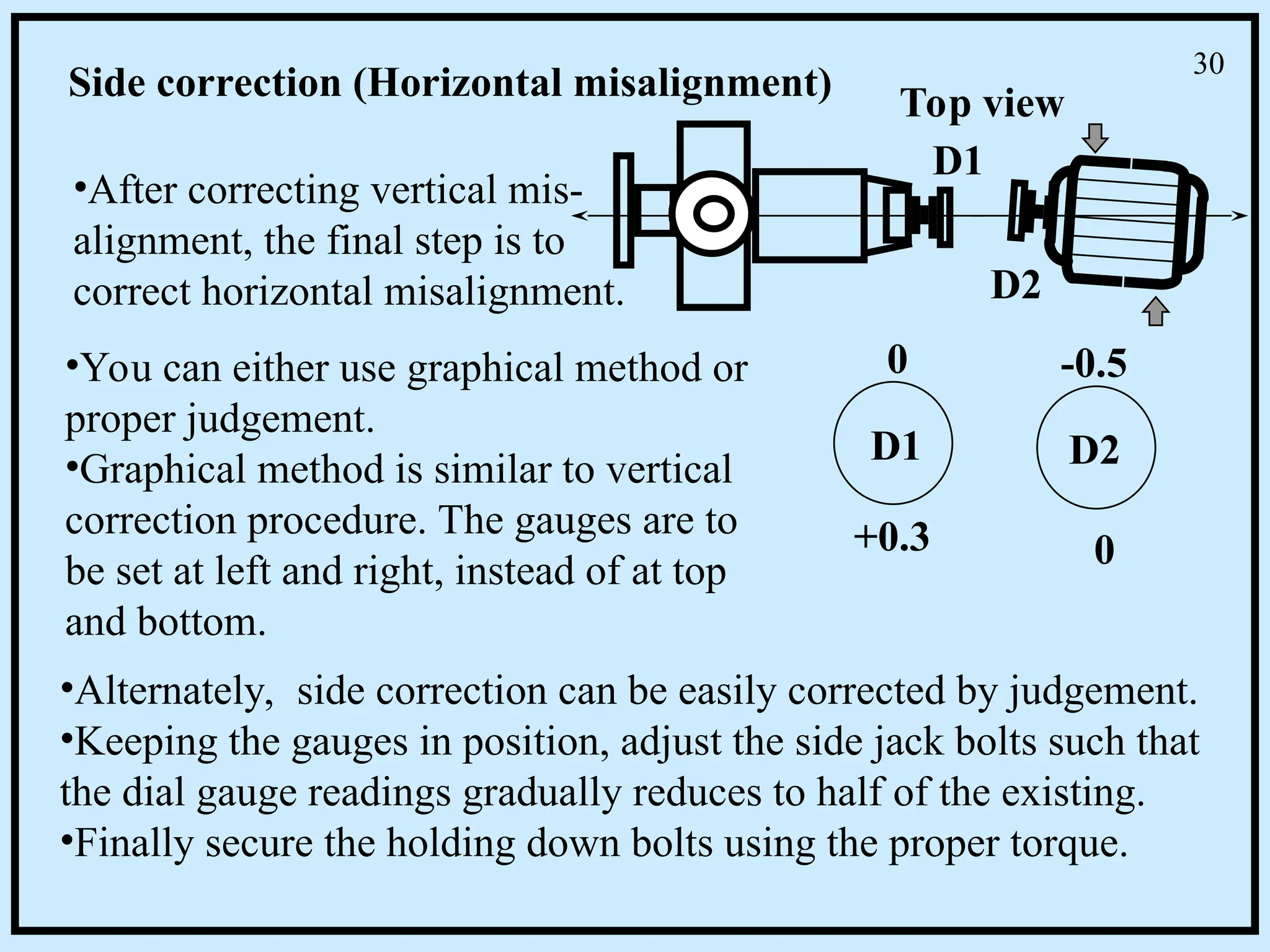
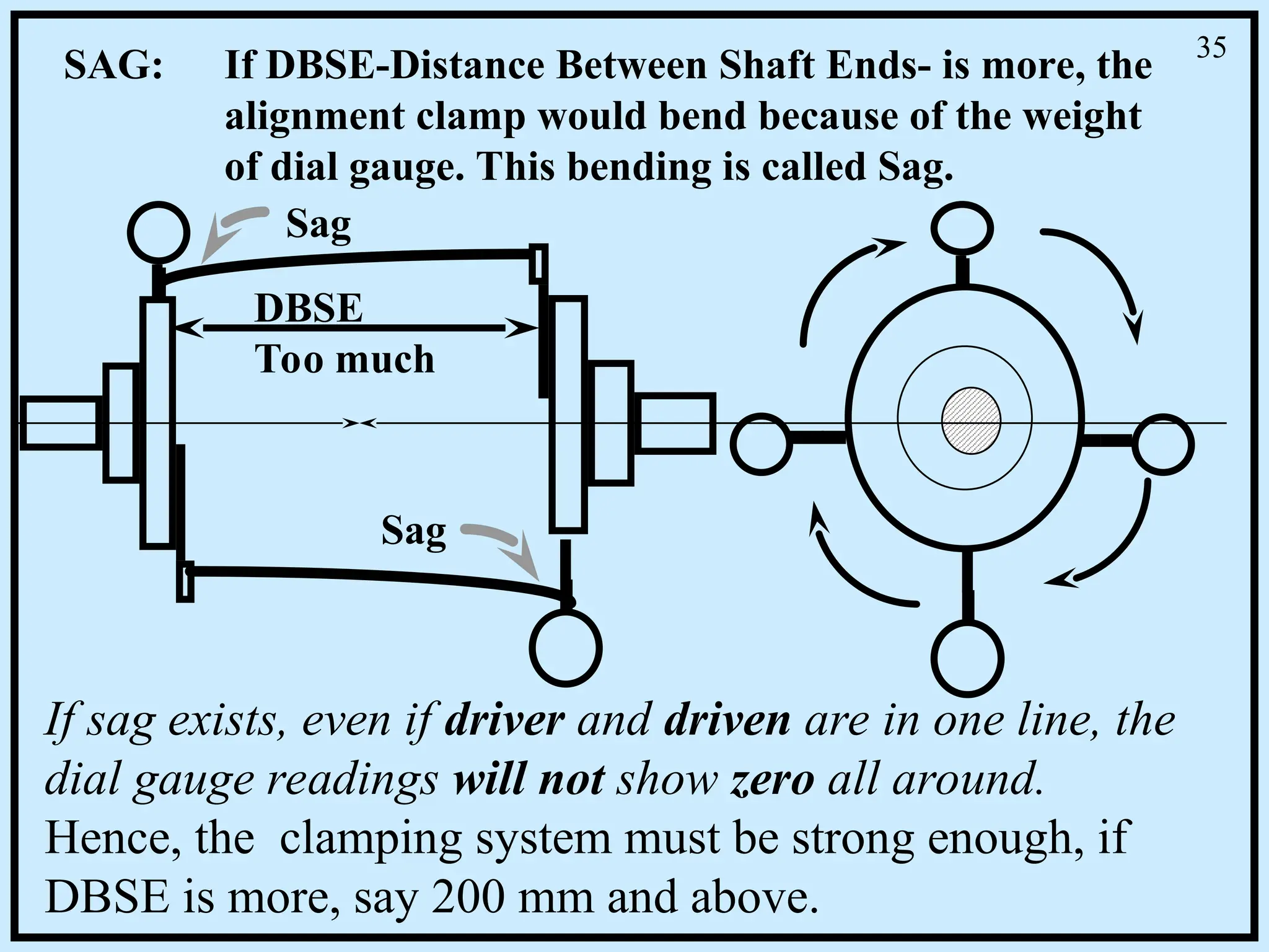
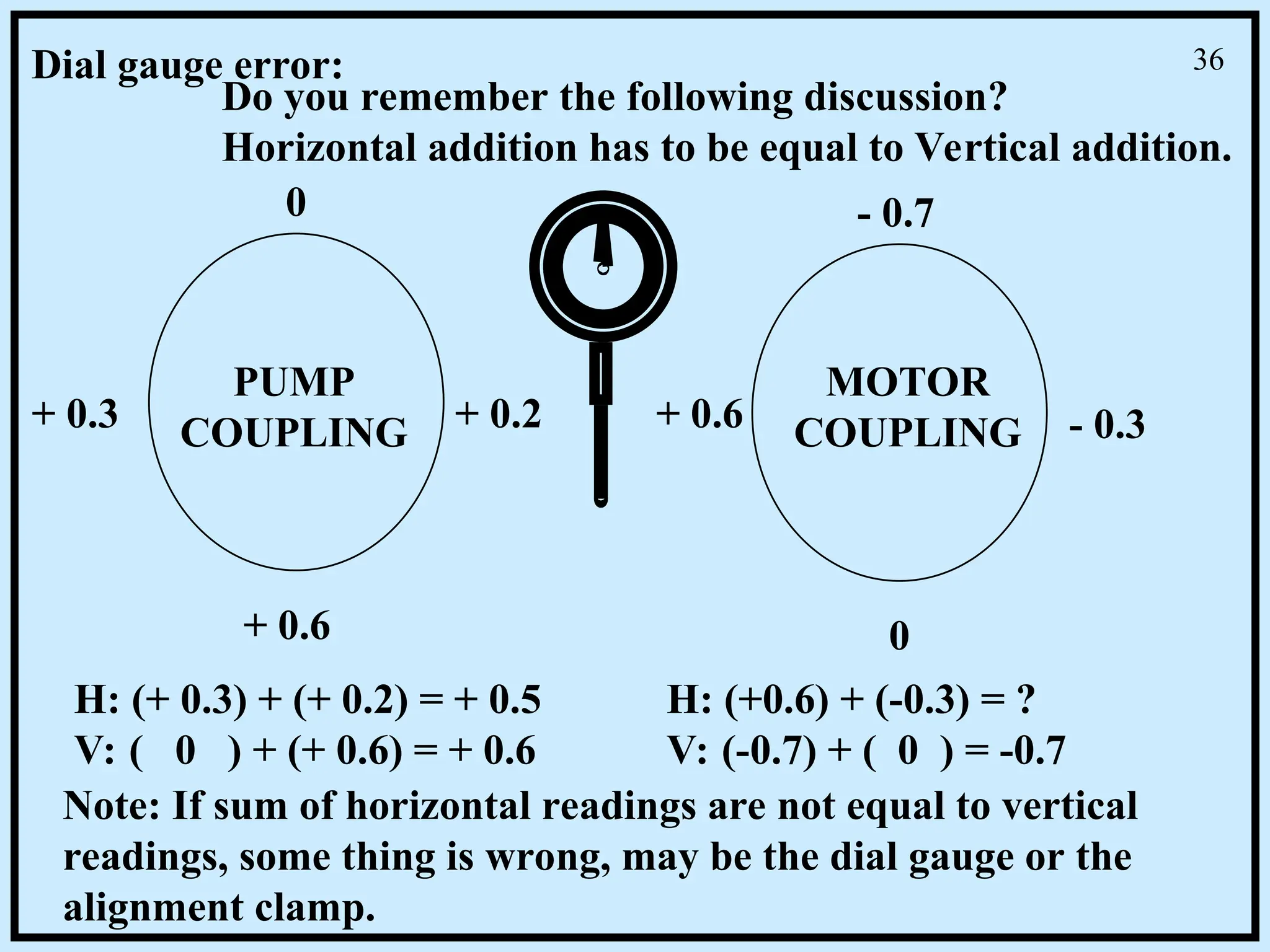
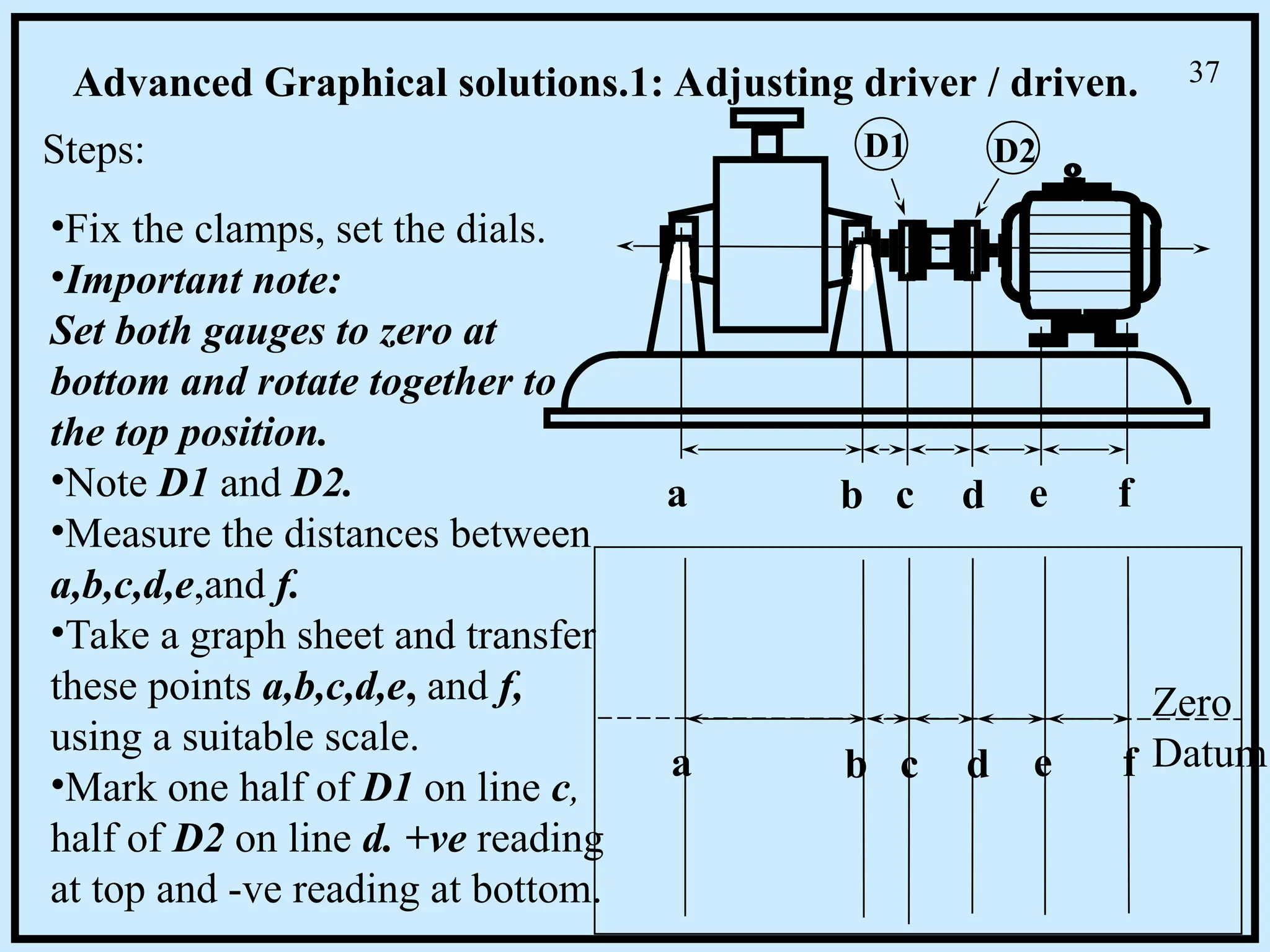
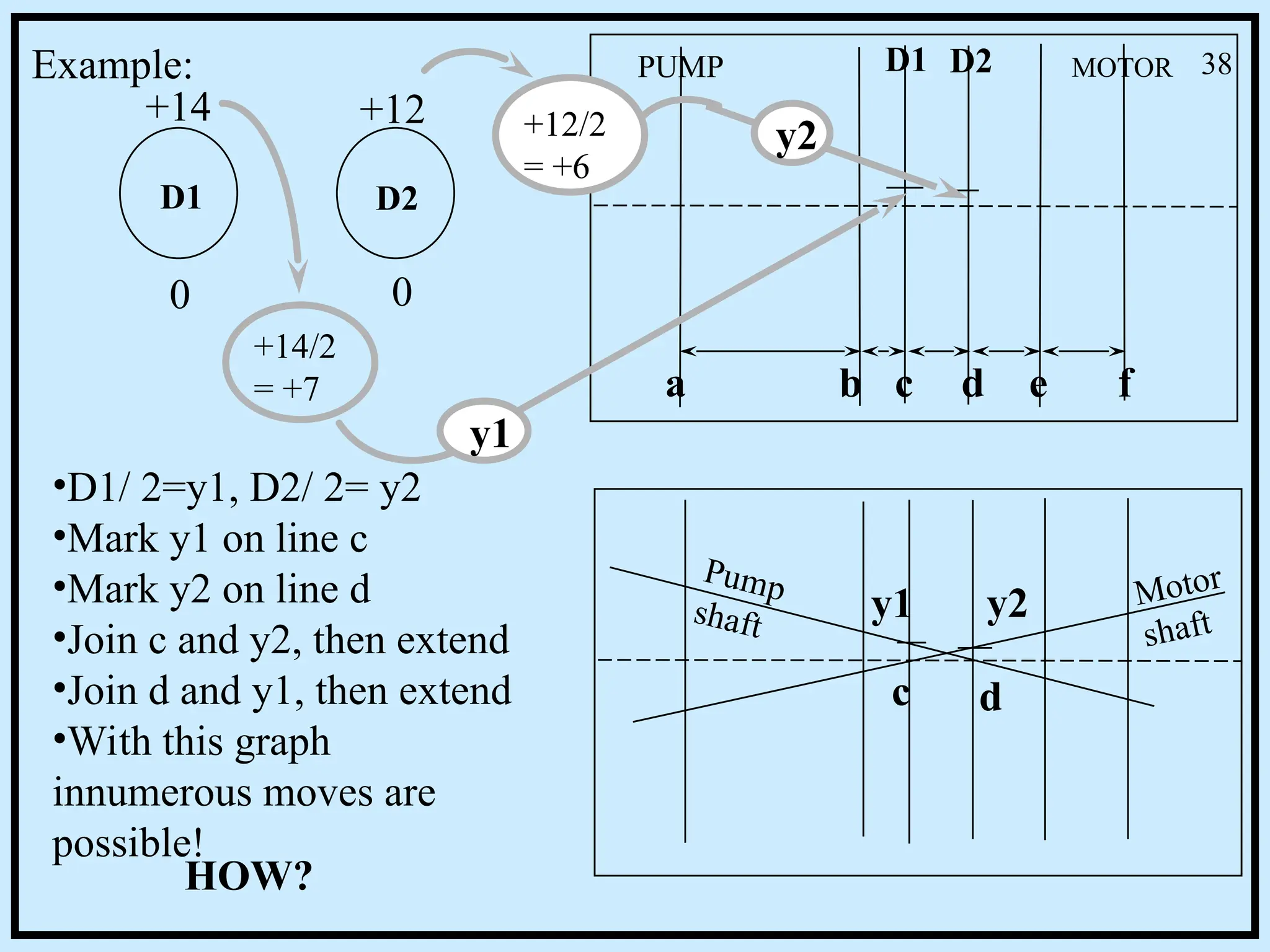
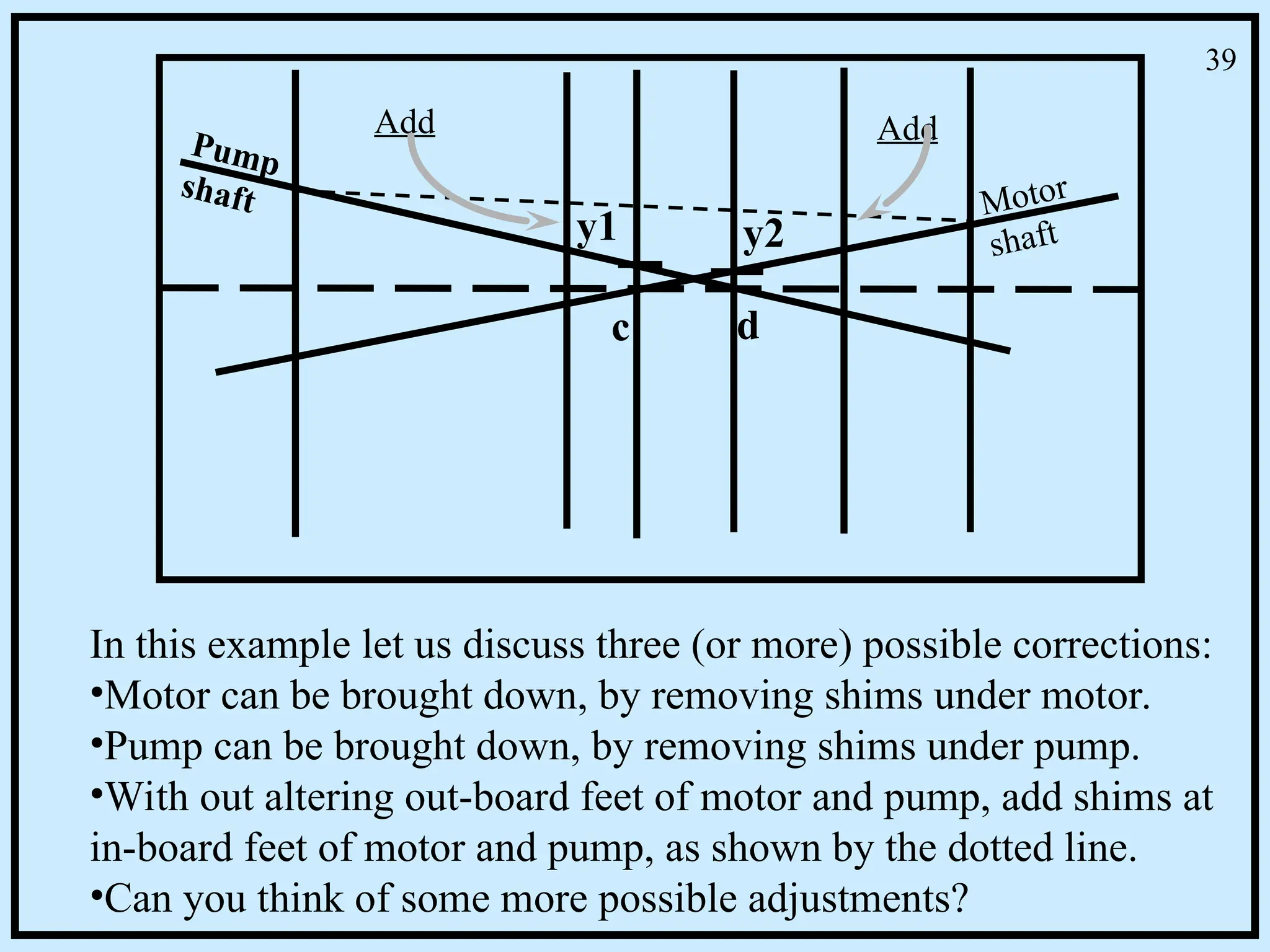
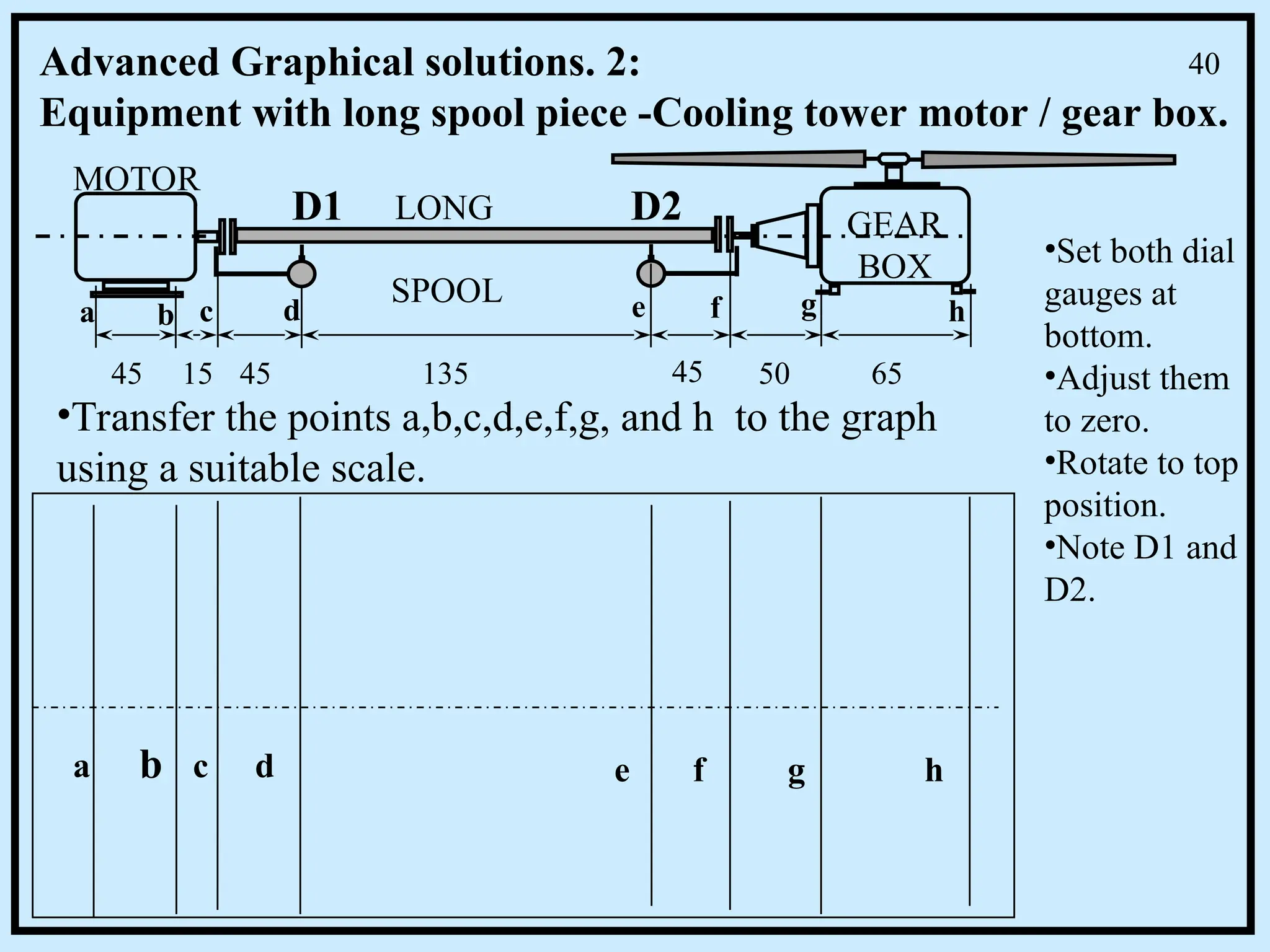
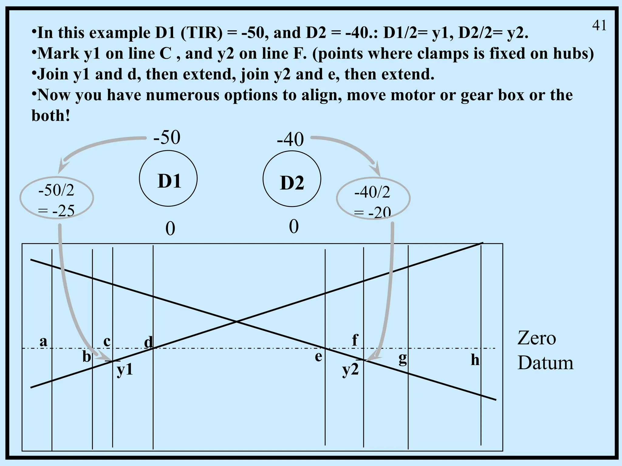
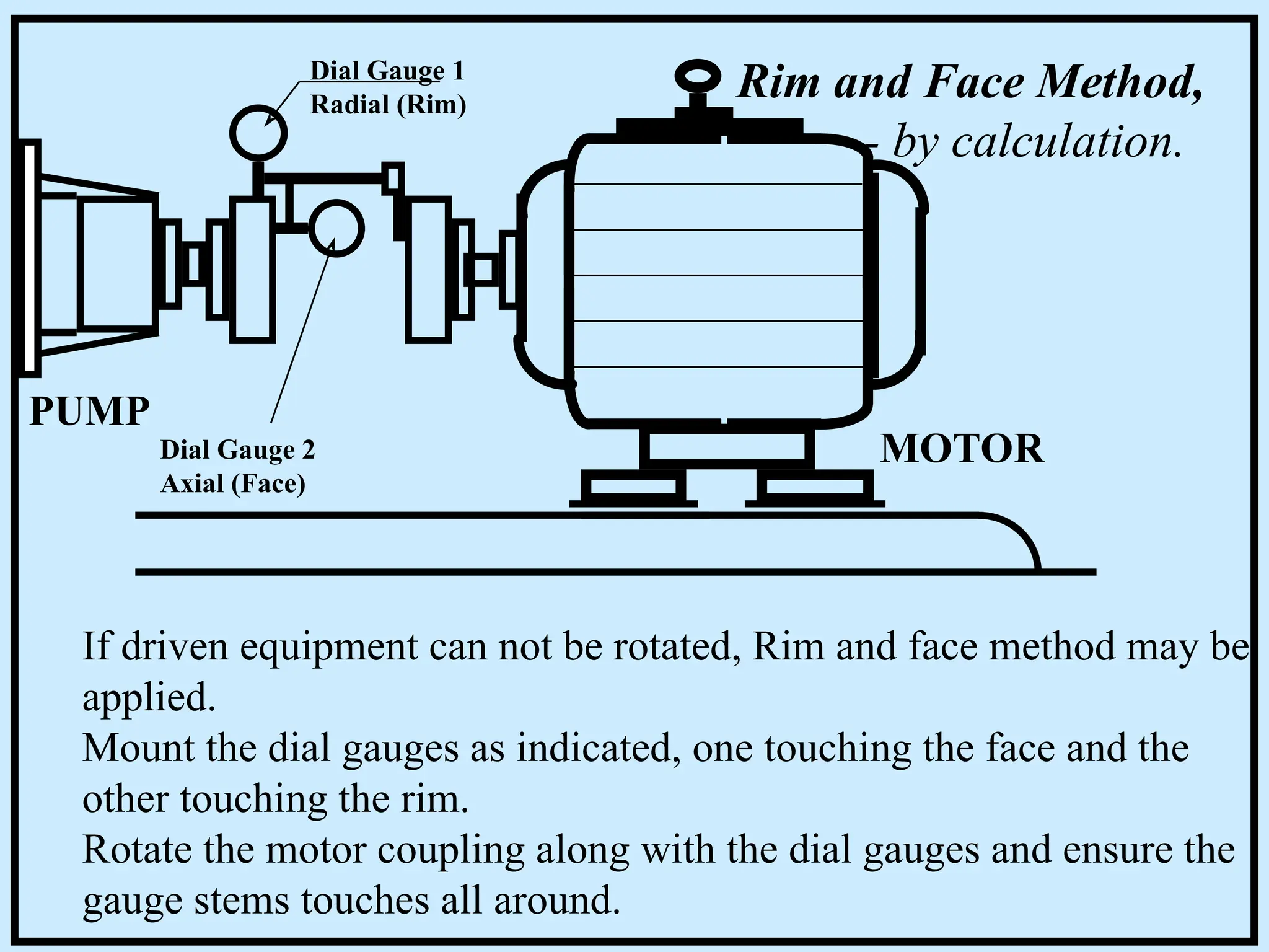
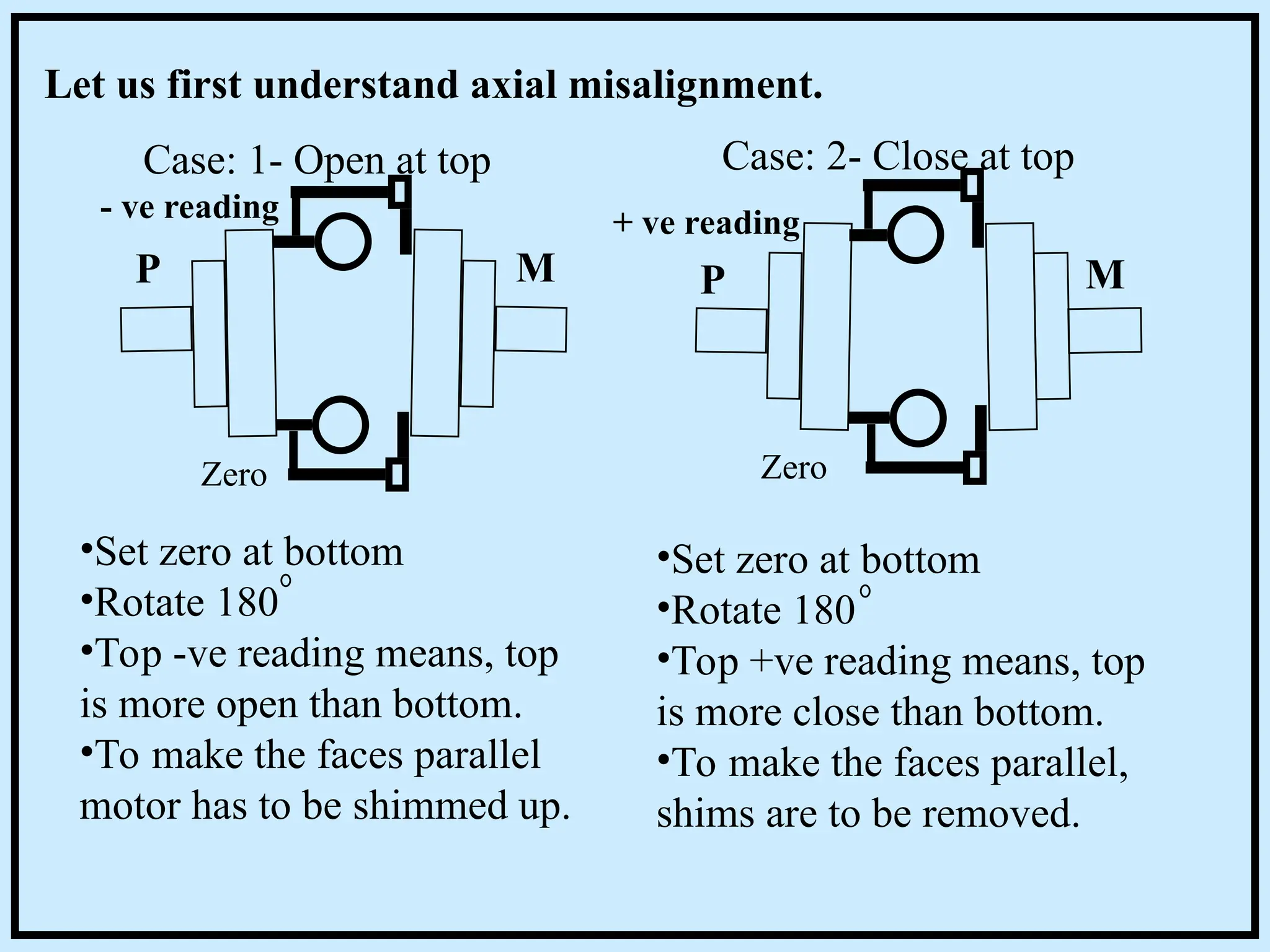
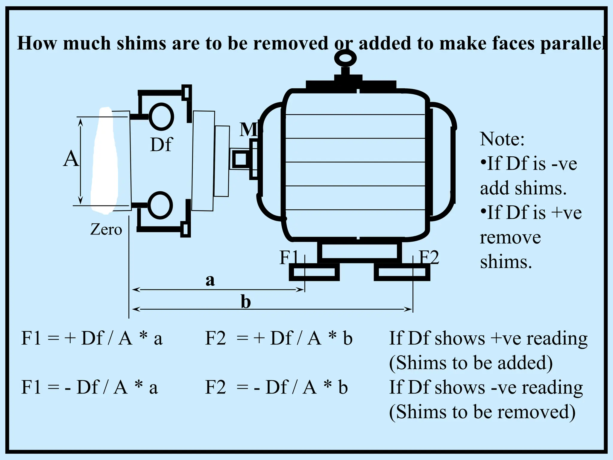
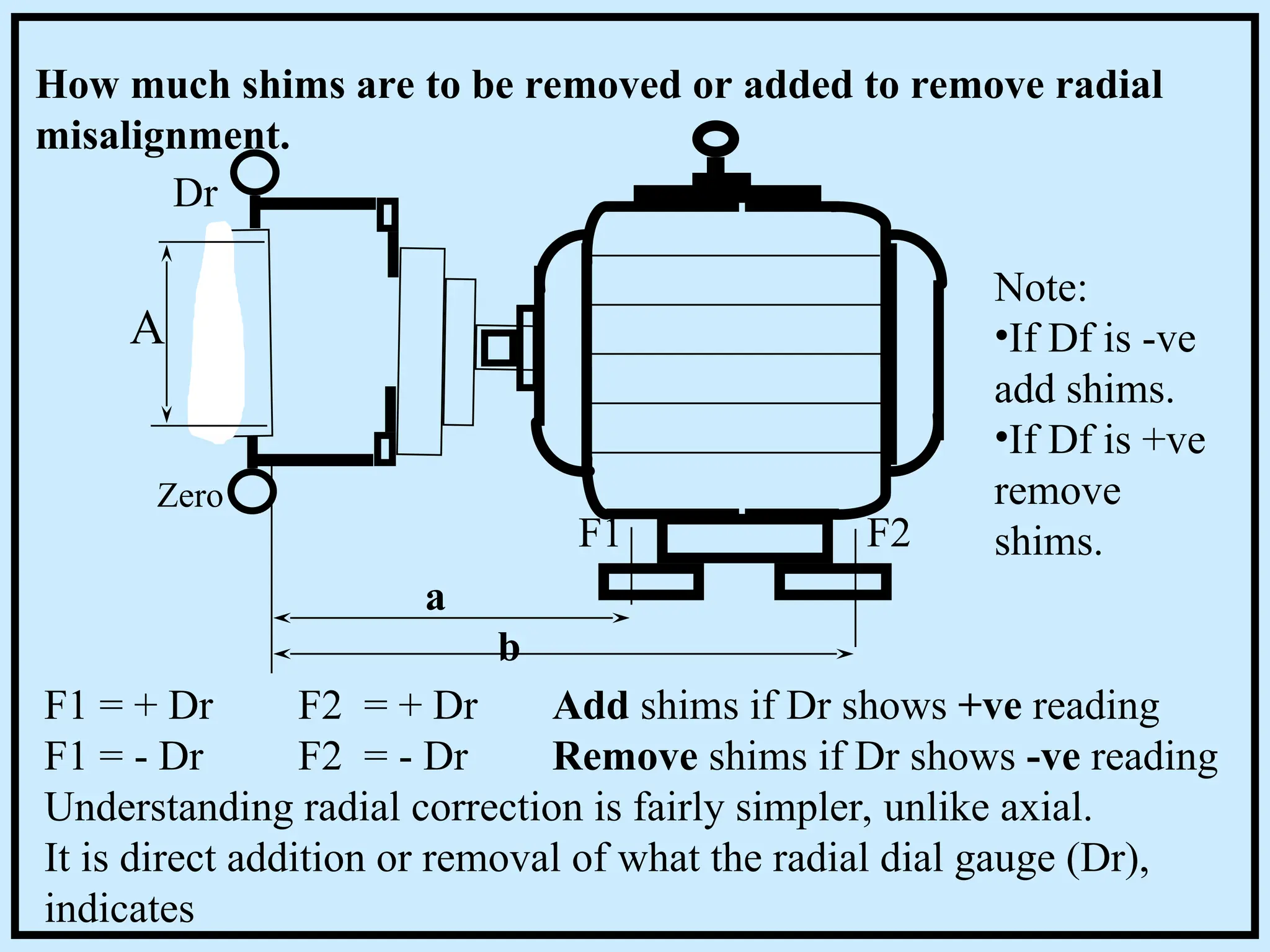
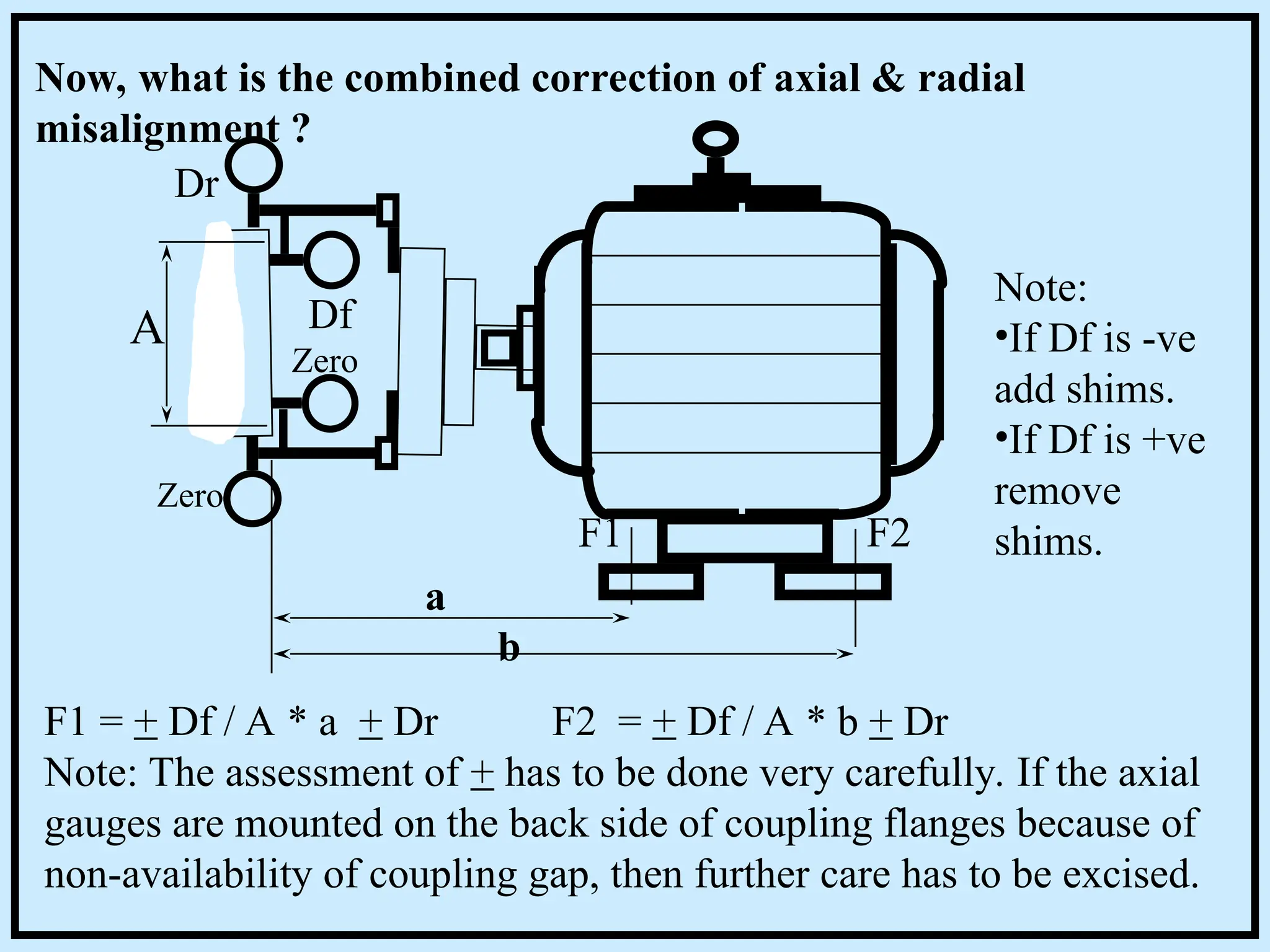
Training Programme on
Alignment
MOTOR
PUMP
Dial Gauge 1
Dial Gauge 2
Pipe strain
Off-set
TIR / 2
Thermal
growth
Step by step Alignment lessons,
starting from the basics,
Not by confusing write-up,
or by mere words, but by
Models and Visuals
a programme by
a well experienced
Rotating equipment
engineer.
Types of flexible couplings
•Chain Coupling
•Diaphragm Coupling
•Elastomeric Coupling
•Flexible Disk Coupling
•Flexible Link Coupling
•Gear Coupling
•Leaf Spring
•Metallic Grid Coupling
•Pin Drive Coupling
Which of the following couplings you have?
Of them which are close couplings and which have spool piece?
Spool
Close
1
The need for proper Alignment
Misalignment causes undesirable effects like:
•High vibration
•Joint leaks
•Internal rubbing
•Cracks
•Coupling failure
•Bearing failures
•Mechanical Seal failures
•Oil seal failures
How do you align your equipment in your company?
•Straight edge?
•Use Dial gauge?
•With dial gauge reading, how do you proceed?
•Trial and error?
•Mathematical formula?
•Graphical method?
•Electronic gadgets, like Calculator or Laser?
2
MOTOR
PUMP
Parallel Misalignment
PUMP MOTOR
Angular Misalignment
How shafts get mis-aligned?
3
MOTOR
PUMP
In reality, on any equipment, both parallel & angular
misalignment exists. Why?
•Improper foundation, base-plate.
•Imperfect pump, motor dimensions.
•Improper pipe support.
•Thermal expansion of pipe line affects alignment.
•Defective concrete base or support.
•Loose or broken foundation bolts.
•Soft foot.
•Shim related problems (loose, rusty, painted, etc)
+
Unclear
knowledge on
proper alignment
practice.
4
MOTOR
PUMP
MOTOR
PUMP
Close Coupling
Spool Piece / Spacer
5
DRIVEN
MOTOR
Close Coupling Alignment
for Low speed drives
(1,500 rpm and less)
Using Straight edge (Scale) and Feeler gauge or taper gauge.
•Make faces of coupling parallel. (Remove angular misalignment)
•Then, make the flanges on one line.(Remove parallel
misalignment)
How?
6
MOTOR
PUMP
How to remove angular
misalignment
Insert feeler gauge at top and at bottom. Record the gap.
If gap not equal, then the faces are not parallel.
Case 1: Top more gap. Remove shim from front foot or add
shim at back foot.
Case 2: Bottom more gap: Remove shim from back foot or
add shim at front foot.
Now the faces will be parallel, but not the center lines.
Front foot Back foot
Feeler gauge
7
Case1: Gap, Top more, bottom less.Case2: Gap, Bottom more, top less.
More
More
Less
Less
After adjusting the faces parallel, both the couplings need not be at the
same level.
M
M
P P
P M P M
Up Up
Dn Dn 8
P M P M
Case1: Remove shim from motor or add shim to pump.
Case2: Remove shim from pump or add shim to motor.
How much shims to add or remove?
Straight edge
Using a feeler gauge
measure the gap
Case1 Case2
Add or remove shim equal to the gap.
9
Review 1 - Straight edge method.
Step 1: Remove angular misalignment.
Step 2: Remove parallel misalignment.
Why so?
How to remove angular misalignment?
How to remove parallel misalignment?
While removing parallel misalignment, on a particular
equipment, you need to remove shims at the back foot of motor,
But there is no shims at that foot. What can be done?
Can dial gauge be used for a better result?
What is dial gauge?
10
+
+
-
-
DIAL
GAUGE
IN
OUT
1. Pushing dial gauge
stem / plunger will show
a +ve reading.
2. Releasing the stem
will show a -ve reading.
3. Dial can be rotated.
Dial
Needle /
Pointer
Stem /
Plunger
11
MOTOR
PUMP
Dial Gauge 1
Dial Gauge 2
Rim and Face Method.
MOTOR
PUMP
Dial Gauge
Radial
Dial Gauge
Axial Dial gauges can be used
for close coupling, if
adequate space available
for fixing gauges.
If the coupling has spool
piece, the axial gauge can
be fixed if spool is
removed.
12
MOTOR
PUMP
Dial Gauge 1
Dial Gauge 2
Limitations:
• Needs space for fixing axial dial.
• Having taken readings, correction need to be calculated,
using similar triangles geometry.
• Excess end float will lead to erroneous reading.
Reverse Periphery Alignment method does not have these
limitations
Rim and Face Method.
13
Reverse Periphery Alignment method
• Set the clamps as shown.
• Always keep the pump - dial at the top & motor - dial at
the bottom position.
MOTOR
PUMP
Dial Gauge 1
Dial Gauge 2
14
The following are two typical misaligned conditions.
Which do you consider is the better?
Case1: Coupling faces are not
parallel, but shaft center lines are
collinear.
Case2: Coupling faces
are parallel, but shaft
center line are not on
one line.
Note: Rotating both couplings together while taking reading will
ensure best alignment, even though faces are not parallel.
15
Reading = 0
Reading = 0
If driver’s center line and driven’s center line are in one
line, then the dial gauge readings will be zero all around
16
If driver center line and driven center line are not in one
line then, the dial gauge readings will not be zero all around
Off-set
+ 0.3
0.0
+ 0.2
+ 0.5 + 0.2
+ 0.5
+ 0.3
0
12
3
6
9
17
If there is only vertical misalignment, then the Offset is
equal to half of TIR ( Total Indicator Reading )
+ 0.25
0.0
+ 0.25
+ 0.5 + 0.25
+ 0.25
Off-set
0
TIR = + 0.5
12
3
6
9
TIR / 2
+0.25
18
0
+ 0.5
+ 0.3
PUMP
COUPLING
0
+ 0.2
MOTOR
COUPLING
- 0.7
- 0.4 - 0.3
STEP1:
•Set the clamps as shown.
•Always keep the pump - dial at the top &
motor - dial at the bottom position.
•Adjust both the gauges to Zero.
•Take a set of dial gauge readings.
# Remember to set zero at the top for pump &
zero at the bottom for motor.
19
+ 0.5
+ 0.3
PUMP
COUPLING
0
+ 0.2
MOTOR
COUPLING
- 0.7
- 0.4 - 0.3
0
Let us understand what does these reading mean.
Horizontal addition has to be equal to Vertical addition.
H: (+ 0.3) + (+ 0.2) = + 0.5
V: ( 0 ) + (+ 0.5) = + 0.5
H: (-0.4) + (-0.3) = -0.7
V: (-0.7) + ( 0 ) = -0.7
Note: If sum of horizontal readings are not equal to vertical
readings, some thing is wrong, may be the dial gauge or the
alignment clamp.
20
Following are two sets of readings, in which pump readings are
OK, but motor readings are not correct.
+ 0.5
+ 0.3
PUMP
COUPLING
0
+ 0.3
MOTOR
COUPLING
- 0.7
- 0.4 + 0.2
0
(+0.3) + (+0.3) = +0.6
is approximately equal to
( 0 ) + (+0.5) = +0.5
(-0.4) + (+0.2) = -0.2
is not equal to
(-0.7) + ( 0 ) = -0.7
21
•Set the alignment clamps such that the dial gauges read the rims of
the couplings.
•Always keep the pump dial gauge at the top and the motor dial gauge
at the bottom position.
•Adjust both dial gauges to zero.
•Rotate both the flanges together along with their dial gauges through
360 degree.
•Note down the readings at 12, 3, 6 and 9 o’ clock positions.
•If the sum of horizontal readings are not equal to vertical readings
suspect erroneous dial gauges or improper clamping system.
•Now we have two sets of dial gauge readings.
REVIEW
22
QUIZ - 1
• In a dial gauge, pressing the plunger will show a -ve reading -
True or False ?
• Releasing the plunger will show a -ve reading - True or False ?
• Are these readings Right or Wrong ?
0
-0.5 -0.7
-1.2 0
+1.0 +0.3
+0.4 0
-1.4 +0.7
-0.8
• Fill in the blanks:
0
-0.6 -0.8
?
0
? +0.7
-2.6 ?
-0.6 +0.4
-0.5
23
PUMP
D 1 D 2
a
b
c
F1 F2
D1: Dial Gauge 1
D2: Dial Gauge 2
F1: Motor Front
foot
F2: Motor Back
foot
Measure the distances: a,b, & c., using a measuring tape.
a= (D1 to D2), b= (D1 to F1), & c = (D1 to F2)
STEP: 2-
24
D 1 D 2
a
b
c
F1 F2
Graph Sheet
Zero Line
Datum
D1 D2 F1 F2
0
STEP:3-
Take a Graph sheet.
• Mark a datum line at 0
• Take suitable scale for ‘a, b, & c and
transfer these distances to the graph.
eg:
a = 24cm
b = 56cm
c =102cm
25
0
+0.7
0
+0.5
Pump
D1
Motor
D2
+0.5/2=+0.25
Offset
D1 D2 F1 F2
0
+0.7/2=+0.35
Offset
Here is a set of readings: D1=+0.5, D2=+0.7.
Divide D1/2 & D2/2
Let D1/2= Y1, D2/2= Y2
Mark this Y1 on line D1
and Y2 on line D2
Why to divide
by 2 !?
Remember
TIR/2 = Offset
26
D1 D2 F1 F2
0
Y1 Y2 H1 H2
Now we have marked Y1 on line D1 and Y2 on line D1.
Next, join Y1 and Y2 and produce until this new line Intersects
F1 and F2.
Measure H1 and H2.
Remove Shims equivalent to H1 and H2 at motor feet.
Depending upon Y1 and Y2, +ve or -ve, H1, and H2 will also be
+ve or -ve.
If H1 and H2 are -ve equivalent shims are to be added.
In our example H1 & H2
are +ve, hence 0.48 mm
shims at foot F1 &
0.67mm shims at F2 are
to be removed for
making alignment
corrections.
27
Quiz - 2: In following four figures, guess the required corrections.
D1 D2 F1 F2
0
Y1 Y2 H1 H2
D1 D2 F1 F2
0
Y1 Y2 H1 H2
D1 D2 F1 F2
0
Y1 Y2 H1 H2
D1 D2 F1 F2
0
Y1 Y2 H1 H2
Fig1: F1- add/remove
F2- add/remove
Fig2: F1- add/remove
F2- add/remove
Fig4: F1- add/remove
F2- add/remove
Fig3: F1- add/remove
F2- add/remove
28
Quiz 3 - Draw graphs for the following 3 sets of dial gauge readings.
PUMP
D 1
D 2
a
b
c
F1 F2
a = 24 cm
b = 56 cm
c = 102 cm
D1
PUMP
D2
MOTOR
0
0
+0.4
-0.3
Case 1: +0.4 -0.3
Case 2: -1.2 -0.8
Case 3: +2.4 +1.6
D1 D2
29
Side correction (Horizontal misalignment)
•After correcting vertical mis-
alignment, the final step is to
correct horizontal misalignment.
0
0
+0.3
-0.5
D1 D2
D1
D2
•You can either use graphical method or
proper judgement.
•Graphical method is similar to vertical
correction procedure. The gauges are to
be set at left and right, instead of at top
and bottom.
•Alternately, side correction can be easily corrected by judgement.
•Keeping the gauges in position, adjust the side jack bolts such that
the dial gauge readings gradually reduces to half of the existing.
•Finally secure the holding down bolts using the proper torque.
Top view
30
Preconditions for alignment:
Having familiarized with alignment method, we
shall now look at some important requirements for
starting alignment.
• Soft foot
• Pipe strain
• Thermal growth
• Sag of alignment clamps
• Dial gauge errors
31
PUMP
D 1 D 2
F1 F2
•Soft foot
Unlike tripod, in
four legged objects
like motor all the legs
may not touch the floor
uniformly.
Some times there could
be a gap under one of
its legs. This particular
leg is called Soft foot
How to identify the existence of Soft foot ?
Keeping the dial gauges in position, loose the motor holding down
bolts one by one. If soft foot exists under a foot, while loosening
you will notice a huge variation in dial gauge reading !
32
Pipe strain
How to identify the existence of Pipe strain ?
Keeping the dial gauges in position, debolt the suction flange,
then the discharge flange. If the dial gauge indicate a huge
variation, then pipe strain exists. Re-adjust the pipe supports
such that the tightening of the flanges will not cause a huge
variation in dial gauge reading.
33
Thermal growth
Alignment is done in
cold condition. Some hot
equipment will grow under
operation.
A quick reading
immediately after shutting
down such equipment will
reveal the existence of
Thermal growth.
For such hot equipment
Thermal growth
compensation has to be
considered.
34
If sag exists, even if driver and driven are in one line, the
dial gauge readings will not show zero all around.
Hence, the clamping system must be strong enough, if
DBSE is more, say 200 mm and above.
DBSE
Too much
Sag
Sag
If DBSE-Distance Between Shaft Ends- is more, the
alignment clamp would bend because of the weight
of dial gauge. This bending is called Sag.
SAG: 35
+ 0.6
+ 0.3
PUMP
COUPLING
0
+ 0.2
MOTOR
COUPLING
- 0.7
+ 0.6 - 0.3
0
Do you remember the following discussion?
Horizontal addition has to be equal to Vertical addition.
H: (+ 0.3) + (+ 0.2) = + 0.5
V: ( 0 ) + (+ 0.6) = + 0.6
H: (+0.6) + (-0.3) = ?
V: (-0.7) + ( 0 ) = -0.7
Note: If sum of horizontal readings are not equal to vertical
readings, some thing is wrong, may be the dial gauge or the
alignment clamp.
Dial gauge error: 36
Advanced Graphical solutions.1: Adjusting driver / driven.
a b c d e f
a b c d e f
D1 D2
Steps:
•Fix the clamps, set the dials.
•Important note:
Set both gauges to zero at
bottom and rotate together to
the top position.
•Note D1 and D2.
•Measure the distances between
a,b,c,d,e,and f.
•Take a graph sheet and transfer
these points a,b,c,d,e, and f,
using a suitable scale.
•Mark one half of D1 on line c,
half of D2 on line d. +ve reading
at top and -ve reading at bottom.
Zero
Datum
37
a b c d e f
D1 D2
Example:
D1 D2
0 0
+14 +12
MOTOR
PUMP
+14/2
= +7
+12/2
= +6
y1
y2
•D1/ 2=y1, D2/ 2= y2
•Mark y1 on line c
•Mark y2 on line d
•Join c and y2, then extend
•Join d and y1, then extend
•With this graph
innumerous moves are
possible!
c d
y1 y2 Motor
shaft
Pump
shaft
HOW?
38
In this example let us discuss three (or more) possible corrections:
•Motor can be brought down, by removing shims under motor.
•Pump can be brought down, by removing shims under pump.
•With out altering out-board feet of motor and pump, add shims at
in-board feet of motor and pump, as shown by the dotted line.
•Can you think of some more possible adjustments?
c d
y1 y2
Motor
shaft
Pump
shaft
Add Add
39
Advanced Graphical solutions. 2:
Equipment with long spool piece -Cooling tower motor / gear box.
45 15 45 135 45 50 65
D1 D2
a b c d e f g h
a b c d e f g h
MOTOR
GEAR
BOX
LONG
SPOOL
•Transfer the points a,b,c,d,e,f,g, and h to the graph
using a suitable scale.
•Set both dial
gauges at
bottom.
•Adjust them
to zero.
•Rotate to top
position.
•Note D1 and
D2.
40
a c d
b e
f
g h
0 0
-50 -40
D1 D2
-50/2
= -25
-40/2
= -20
•In this example D1 (TIR) = -50, and D2 = -40.: D1/2= y1, D2/2= y2.
•Mark y1 on line C , and y2 on line F. (points where clamps is fixed on hubs)
•Join y1 and d, then extend, join y2 and e, then extend.
•Now you have numerous options to align, move motor or gear box or the
both!
y1 y2
Zero
Datum
41
MOTOR
PUMP
Dial Gauge 1
Radial (Rim)
Dial Gauge 2
Axial (Face)
Rim and Face Method,
- by calculation.
If driven equipment can not be rotated, Rim and face method may be
applied.
Mount the dial gauges as indicated, one touching the face and the
other touching the rim.
Rotate the motor coupling along with the dial gauges and ensure the
gauge stems touches all around.
- ve reading
Zero
P M P M
Zero
+ ve reading
Let us first understand axial misalignment.
Case: 1- Open at top Case: 2- Close at top
•Set zero at bottom
•Rotate 180
•Top -ve reading means, top
is more open than bottom.
•To make the faces parallel
motor has to be shimmed up.
•Set zero at bottom
•Rotate 180
•Top +ve reading means, top
is more close than bottom.
•To make the faces parallel,
shims are to be removed.
Zero
M
A
a
b
Df
How much shims are to be removed or added to make faces parallel
Note:
•If Df is -ve
add shims.
•If Df is +ve
remove
shims.
F1 F2
F1 = + Df / A * a F2 = + Df / A * b If Df shows +ve reading
(Shims to be added)
F1 = - Df / A * a F2 = - Df / A * b If Df shows -ve reading
(Shims to be removed)
Zero
A
a
b
Dr
How much shims are to be removed or added to remove radial
misalignment.
Note:
•If Df is -ve
add shims.
•If Df is +ve
remove
shims.
F1 F2
F1 = + Dr F2 = + Dr Add shims if Dr shows +ve reading
F1 = - Dr F2 = - Dr Remove shims if Dr shows -ve reading
Understanding radial correction is fairly simpler, unlike axial.
It is direct addition or removal of what the radial dial gauge (Dr),
indicates
Zero
A
a
b
Dr
Now, what is the combined correction of axial & radial
misalignment ?
Note:
•If Df is -ve
add shims.
•If Df is +ve
remove
shims.
F1 F2
F1 = + Df / A * a + Dr F2 = + Df / A * b + Dr
Note: The assessment of + has to be done very carefully. If the axial
gauges are mounted on the back side of coupling flanges because of
non-availability of coupling gap, then further care has to be excised.
Df
Zero

Final alignment of rotary equipment like pump.ppt

  • 1.
    Training Programme on TrainingProgramme on Alignment
  • 2.
    MOTOR PUMP Dial Gauge 1 DialGauge 2 Pipe strain Off-set TIR / 2 Thermal growth Step by step Alignment lessons, starting from the basics, Not by confusing write-up, or by mere words, but by Models and Visuals a programme by a well experienced Rotating equipment engineer.
  • 3.
    Types of flexiblecouplings •Chain Coupling •Diaphragm Coupling •Elastomeric Coupling •Flexible Disk Coupling •Flexible Link Coupling •Gear Coupling •Leaf Spring •Metallic Grid Coupling •Pin Drive Coupling Which of the following couplings you have? Of them which are close couplings and which have spool piece? Spool Close 1
  • 4.
    The need forproper Alignment Misalignment causes undesirable effects like: •High vibration •Joint leaks •Internal rubbing •Cracks •Coupling failure •Bearing failures •Mechanical Seal failures •Oil seal failures How do you align your equipment in your company? •Straight edge? •Use Dial gauge? •With dial gauge reading, how do you proceed? •Trial and error? •Mathematical formula? •Graphical method? •Electronic gadgets, like Calculator or Laser? 2
  • 5.
    MOTOR PUMP Parallel Misalignment PUMP MOTOR AngularMisalignment How shafts get mis-aligned? 3
  • 6.
    MOTOR PUMP In reality, onany equipment, both parallel & angular misalignment exists. Why? •Improper foundation, base-plate. •Imperfect pump, motor dimensions. •Improper pipe support. •Thermal expansion of pipe line affects alignment. •Defective concrete base or support. •Loose or broken foundation bolts. •Soft foot. •Shim related problems (loose, rusty, painted, etc) + Unclear knowledge on proper alignment practice. 4
  • 7.
  • 8.
    DRIVEN MOTOR Close Coupling Alignment forLow speed drives (1,500 rpm and less) Using Straight edge (Scale) and Feeler gauge or taper gauge. •Make faces of coupling parallel. (Remove angular misalignment) •Then, make the flanges on one line.(Remove parallel misalignment) How? 6
  • 9.
    MOTOR PUMP How to removeangular misalignment Insert feeler gauge at top and at bottom. Record the gap. If gap not equal, then the faces are not parallel. Case 1: Top more gap. Remove shim from front foot or add shim at back foot. Case 2: Bottom more gap: Remove shim from back foot or add shim at front foot. Now the faces will be parallel, but not the center lines. Front foot Back foot Feeler gauge 7
  • 10.
    Case1: Gap, Topmore, bottom less.Case2: Gap, Bottom more, top less. More More Less Less After adjusting the faces parallel, both the couplings need not be at the same level. M M P P P M P M Up Up Dn Dn 8
  • 11.
    P M PM Case1: Remove shim from motor or add shim to pump. Case2: Remove shim from pump or add shim to motor. How much shims to add or remove? Straight edge Using a feeler gauge measure the gap Case1 Case2 Add or remove shim equal to the gap. 9
  • 12.
    Review 1 -Straight edge method. Step 1: Remove angular misalignment. Step 2: Remove parallel misalignment. Why so? How to remove angular misalignment? How to remove parallel misalignment? While removing parallel misalignment, on a particular equipment, you need to remove shims at the back foot of motor, But there is no shims at that foot. What can be done? Can dial gauge be used for a better result? What is dial gauge? 10
  • 13.
    + + - - DIAL GAUGE IN OUT 1. Pushing dialgauge stem / plunger will show a +ve reading. 2. Releasing the stem will show a -ve reading. 3. Dial can be rotated. Dial Needle / Pointer Stem / Plunger 11
  • 14.
    MOTOR PUMP Dial Gauge 1 DialGauge 2 Rim and Face Method. MOTOR PUMP Dial Gauge Radial Dial Gauge Axial Dial gauges can be used for close coupling, if adequate space available for fixing gauges. If the coupling has spool piece, the axial gauge can be fixed if spool is removed. 12
  • 15.
    MOTOR PUMP Dial Gauge 1 DialGauge 2 Limitations: • Needs space for fixing axial dial. • Having taken readings, correction need to be calculated, using similar triangles geometry. • Excess end float will lead to erroneous reading. Reverse Periphery Alignment method does not have these limitations Rim and Face Method. 13
  • 16.
    Reverse Periphery Alignmentmethod • Set the clamps as shown. • Always keep the pump - dial at the top & motor - dial at the bottom position. MOTOR PUMP Dial Gauge 1 Dial Gauge 2 14
  • 17.
    The following aretwo typical misaligned conditions. Which do you consider is the better? Case1: Coupling faces are not parallel, but shaft center lines are collinear. Case2: Coupling faces are parallel, but shaft center line are not on one line. Note: Rotating both couplings together while taking reading will ensure best alignment, even though faces are not parallel. 15
  • 18.
    Reading = 0 Reading= 0 If driver’s center line and driven’s center line are in one line, then the dial gauge readings will be zero all around 16
  • 19.
    If driver centerline and driven center line are not in one line then, the dial gauge readings will not be zero all around Off-set + 0.3 0.0 + 0.2 + 0.5 + 0.2 + 0.5 + 0.3 0 12 3 6 9 17
  • 20.
    If there isonly vertical misalignment, then the Offset is equal to half of TIR ( Total Indicator Reading ) + 0.25 0.0 + 0.25 + 0.5 + 0.25 + 0.25 Off-set 0 TIR = + 0.5 12 3 6 9 TIR / 2 +0.25 18
  • 21.
    0 + 0.5 + 0.3 PUMP COUPLING 0 +0.2 MOTOR COUPLING - 0.7 - 0.4 - 0.3 STEP1: •Set the clamps as shown. •Always keep the pump - dial at the top & motor - dial at the bottom position. •Adjust both the gauges to Zero. •Take a set of dial gauge readings. # Remember to set zero at the top for pump & zero at the bottom for motor. 19
  • 22.
    + 0.5 + 0.3 PUMP COUPLING 0 +0.2 MOTOR COUPLING - 0.7 - 0.4 - 0.3 0 Let us understand what does these reading mean. Horizontal addition has to be equal to Vertical addition. H: (+ 0.3) + (+ 0.2) = + 0.5 V: ( 0 ) + (+ 0.5) = + 0.5 H: (-0.4) + (-0.3) = -0.7 V: (-0.7) + ( 0 ) = -0.7 Note: If sum of horizontal readings are not equal to vertical readings, some thing is wrong, may be the dial gauge or the alignment clamp. 20
  • 23.
    Following are twosets of readings, in which pump readings are OK, but motor readings are not correct. + 0.5 + 0.3 PUMP COUPLING 0 + 0.3 MOTOR COUPLING - 0.7 - 0.4 + 0.2 0 (+0.3) + (+0.3) = +0.6 is approximately equal to ( 0 ) + (+0.5) = +0.5 (-0.4) + (+0.2) = -0.2 is not equal to (-0.7) + ( 0 ) = -0.7 21
  • 24.
    •Set the alignmentclamps such that the dial gauges read the rims of the couplings. •Always keep the pump dial gauge at the top and the motor dial gauge at the bottom position. •Adjust both dial gauges to zero. •Rotate both the flanges together along with their dial gauges through 360 degree. •Note down the readings at 12, 3, 6 and 9 o’ clock positions. •If the sum of horizontal readings are not equal to vertical readings suspect erroneous dial gauges or improper clamping system. •Now we have two sets of dial gauge readings. REVIEW 22
  • 25.
    QUIZ - 1 •In a dial gauge, pressing the plunger will show a -ve reading - True or False ? • Releasing the plunger will show a -ve reading - True or False ? • Are these readings Right or Wrong ? 0 -0.5 -0.7 -1.2 0 +1.0 +0.3 +0.4 0 -1.4 +0.7 -0.8 • Fill in the blanks: 0 -0.6 -0.8 ? 0 ? +0.7 -2.6 ? -0.6 +0.4 -0.5 23
  • 26.
    PUMP D 1 D2 a b c F1 F2 D1: Dial Gauge 1 D2: Dial Gauge 2 F1: Motor Front foot F2: Motor Back foot Measure the distances: a,b, & c., using a measuring tape. a= (D1 to D2), b= (D1 to F1), & c = (D1 to F2) STEP: 2- 24
  • 27.
    D 1 D2 a b c F1 F2 Graph Sheet Zero Line Datum D1 D2 F1 F2 0 STEP:3- Take a Graph sheet. • Mark a datum line at 0 • Take suitable scale for ‘a, b, & c and transfer these distances to the graph. eg: a = 24cm b = 56cm c =102cm 25
  • 28.
    0 +0.7 0 +0.5 Pump D1 Motor D2 +0.5/2=+0.25 Offset D1 D2 F1F2 0 +0.7/2=+0.35 Offset Here is a set of readings: D1=+0.5, D2=+0.7. Divide D1/2 & D2/2 Let D1/2= Y1, D2/2= Y2 Mark this Y1 on line D1 and Y2 on line D2 Why to divide by 2 !? Remember TIR/2 = Offset 26
  • 29.
    D1 D2 F1F2 0 Y1 Y2 H1 H2 Now we have marked Y1 on line D1 and Y2 on line D1. Next, join Y1 and Y2 and produce until this new line Intersects F1 and F2. Measure H1 and H2. Remove Shims equivalent to H1 and H2 at motor feet. Depending upon Y1 and Y2, +ve or -ve, H1, and H2 will also be +ve or -ve. If H1 and H2 are -ve equivalent shims are to be added. In our example H1 & H2 are +ve, hence 0.48 mm shims at foot F1 & 0.67mm shims at F2 are to be removed for making alignment corrections. 27
  • 30.
    Quiz - 2:In following four figures, guess the required corrections. D1 D2 F1 F2 0 Y1 Y2 H1 H2 D1 D2 F1 F2 0 Y1 Y2 H1 H2 D1 D2 F1 F2 0 Y1 Y2 H1 H2 D1 D2 F1 F2 0 Y1 Y2 H1 H2 Fig1: F1- add/remove F2- add/remove Fig2: F1- add/remove F2- add/remove Fig4: F1- add/remove F2- add/remove Fig3: F1- add/remove F2- add/remove 28
  • 31.
    Quiz 3 -Draw graphs for the following 3 sets of dial gauge readings. PUMP D 1 D 2 a b c F1 F2 a = 24 cm b = 56 cm c = 102 cm D1 PUMP D2 MOTOR 0 0 +0.4 -0.3 Case 1: +0.4 -0.3 Case 2: -1.2 -0.8 Case 3: +2.4 +1.6 D1 D2 29
  • 32.
    Side correction (Horizontalmisalignment) •After correcting vertical mis- alignment, the final step is to correct horizontal misalignment. 0 0 +0.3 -0.5 D1 D2 D1 D2 •You can either use graphical method or proper judgement. •Graphical method is similar to vertical correction procedure. The gauges are to be set at left and right, instead of at top and bottom. •Alternately, side correction can be easily corrected by judgement. •Keeping the gauges in position, adjust the side jack bolts such that the dial gauge readings gradually reduces to half of the existing. •Finally secure the holding down bolts using the proper torque. Top view 30
  • 33.
    Preconditions for alignment: Havingfamiliarized with alignment method, we shall now look at some important requirements for starting alignment. • Soft foot • Pipe strain • Thermal growth • Sag of alignment clamps • Dial gauge errors 31
  • 34.
    PUMP D 1 D2 F1 F2 •Soft foot Unlike tripod, in four legged objects like motor all the legs may not touch the floor uniformly. Some times there could be a gap under one of its legs. This particular leg is called Soft foot How to identify the existence of Soft foot ? Keeping the dial gauges in position, loose the motor holding down bolts one by one. If soft foot exists under a foot, while loosening you will notice a huge variation in dial gauge reading ! 32
  • 35.
    Pipe strain How toidentify the existence of Pipe strain ? Keeping the dial gauges in position, debolt the suction flange, then the discharge flange. If the dial gauge indicate a huge variation, then pipe strain exists. Re-adjust the pipe supports such that the tightening of the flanges will not cause a huge variation in dial gauge reading. 33
  • 36.
    Thermal growth Alignment isdone in cold condition. Some hot equipment will grow under operation. A quick reading immediately after shutting down such equipment will reveal the existence of Thermal growth. For such hot equipment Thermal growth compensation has to be considered. 34
  • 37.
    If sag exists,even if driver and driven are in one line, the dial gauge readings will not show zero all around. Hence, the clamping system must be strong enough, if DBSE is more, say 200 mm and above. DBSE Too much Sag Sag If DBSE-Distance Between Shaft Ends- is more, the alignment clamp would bend because of the weight of dial gauge. This bending is called Sag. SAG: 35
  • 38.
    + 0.6 + 0.3 PUMP COUPLING 0 +0.2 MOTOR COUPLING - 0.7 + 0.6 - 0.3 0 Do you remember the following discussion? Horizontal addition has to be equal to Vertical addition. H: (+ 0.3) + (+ 0.2) = + 0.5 V: ( 0 ) + (+ 0.6) = + 0.6 H: (+0.6) + (-0.3) = ? V: (-0.7) + ( 0 ) = -0.7 Note: If sum of horizontal readings are not equal to vertical readings, some thing is wrong, may be the dial gauge or the alignment clamp. Dial gauge error: 36
  • 39.
    Advanced Graphical solutions.1:Adjusting driver / driven. a b c d e f a b c d e f D1 D2 Steps: •Fix the clamps, set the dials. •Important note: Set both gauges to zero at bottom and rotate together to the top position. •Note D1 and D2. •Measure the distances between a,b,c,d,e,and f. •Take a graph sheet and transfer these points a,b,c,d,e, and f, using a suitable scale. •Mark one half of D1 on line c, half of D2 on line d. +ve reading at top and -ve reading at bottom. Zero Datum 37
  • 40.
    a b cd e f D1 D2 Example: D1 D2 0 0 +14 +12 MOTOR PUMP +14/2 = +7 +12/2 = +6 y1 y2 •D1/ 2=y1, D2/ 2= y2 •Mark y1 on line c •Mark y2 on line d •Join c and y2, then extend •Join d and y1, then extend •With this graph innumerous moves are possible! c d y1 y2 Motor shaft Pump shaft HOW? 38
  • 41.
    In this examplelet us discuss three (or more) possible corrections: •Motor can be brought down, by removing shims under motor. •Pump can be brought down, by removing shims under pump. •With out altering out-board feet of motor and pump, add shims at in-board feet of motor and pump, as shown by the dotted line. •Can you think of some more possible adjustments? c d y1 y2 Motor shaft Pump shaft Add Add 39
  • 42.
    Advanced Graphical solutions.2: Equipment with long spool piece -Cooling tower motor / gear box. 45 15 45 135 45 50 65 D1 D2 a b c d e f g h a b c d e f g h MOTOR GEAR BOX LONG SPOOL •Transfer the points a,b,c,d,e,f,g, and h to the graph using a suitable scale. •Set both dial gauges at bottom. •Adjust them to zero. •Rotate to top position. •Note D1 and D2. 40
  • 43.
    a c d be f g h 0 0 -50 -40 D1 D2 -50/2 = -25 -40/2 = -20 •In this example D1 (TIR) = -50, and D2 = -40.: D1/2= y1, D2/2= y2. •Mark y1 on line C , and y2 on line F. (points where clamps is fixed on hubs) •Join y1 and d, then extend, join y2 and e, then extend. •Now you have numerous options to align, move motor or gear box or the both! y1 y2 Zero Datum 41
  • 44.
    MOTOR PUMP Dial Gauge 1 Radial(Rim) Dial Gauge 2 Axial (Face) Rim and Face Method, - by calculation. If driven equipment can not be rotated, Rim and face method may be applied. Mount the dial gauges as indicated, one touching the face and the other touching the rim. Rotate the motor coupling along with the dial gauges and ensure the gauge stems touches all around.
  • 45.
    - ve reading Zero PM P M Zero + ve reading Let us first understand axial misalignment. Case: 1- Open at top Case: 2- Close at top •Set zero at bottom •Rotate 180 •Top -ve reading means, top is more open than bottom. •To make the faces parallel motor has to be shimmed up. •Set zero at bottom •Rotate 180 •Top +ve reading means, top is more close than bottom. •To make the faces parallel, shims are to be removed.
  • 46.
    Zero M A a b Df How much shimsare to be removed or added to make faces parallel Note: •If Df is -ve add shims. •If Df is +ve remove shims. F1 F2 F1 = + Df / A * a F2 = + Df / A * b If Df shows +ve reading (Shims to be added) F1 = - Df / A * a F2 = - Df / A * b If Df shows -ve reading (Shims to be removed)
  • 47.
    Zero A a b Dr How much shimsare to be removed or added to remove radial misalignment. Note: •If Df is -ve add shims. •If Df is +ve remove shims. F1 F2 F1 = + Dr F2 = + Dr Add shims if Dr shows +ve reading F1 = - Dr F2 = - Dr Remove shims if Dr shows -ve reading Understanding radial correction is fairly simpler, unlike axial. It is direct addition or removal of what the radial dial gauge (Dr), indicates
  • 48.
    Zero A a b Dr Now, what isthe combined correction of axial & radial misalignment ? Note: •If Df is -ve add shims. •If Df is +ve remove shims. F1 F2 F1 = + Df / A * a + Dr F2 = + Df / A * b + Dr Note: The assessment of + has to be done very carefully. If the axial gauges are mounted on the back side of coupling flanges because of non-availability of coupling gap, then further care has to be excised. Df Zero