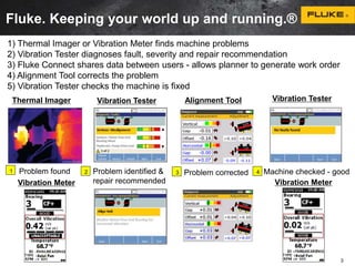
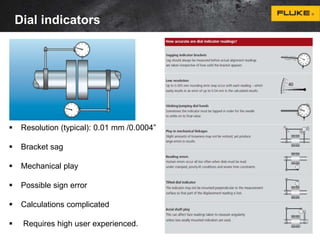
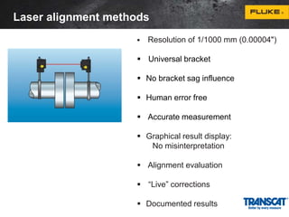
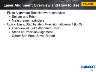
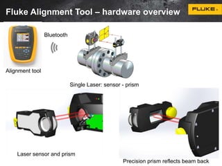
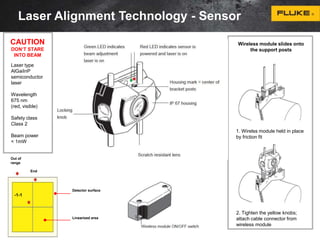
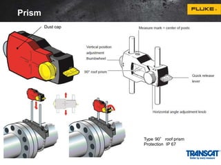
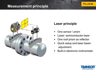
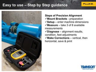
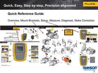
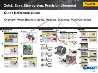
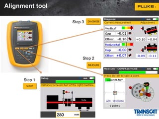
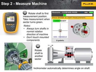
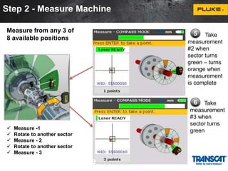
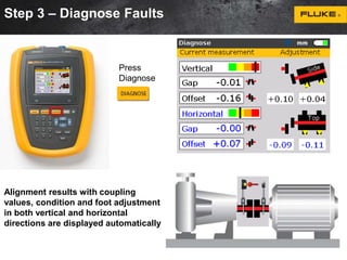
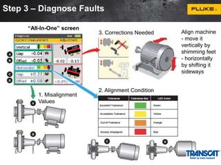
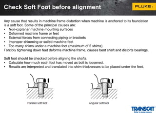
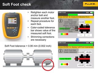
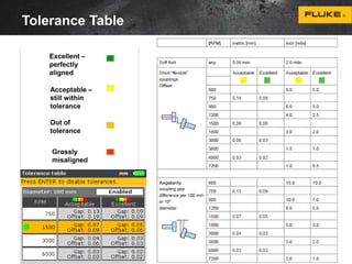
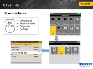
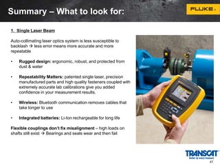
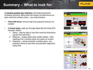
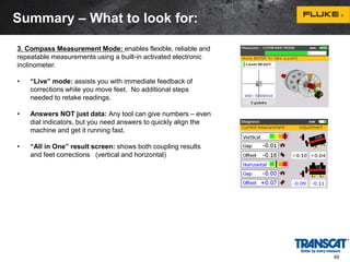
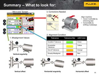
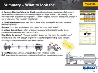
The document discusses precision laser shaft alignment using the Fluke 830 Laser Alignment tool. It provides an overview of the benefits of precision alignment, describes laser alignment principles and the Fluke tool. The Fluke tool allows for quick, easy, and precise alignment in 3 steps: setup, measurement, and diagnosis/correction. It provides intuitive guidance and diagnostic information to correctly align shafts and maximize machine reliability and uptime.
Vibration analysis can provide very useful information about the status of the equipment and the nature and severity of the problem.
It is possible to use these information to plan all maintenance activities and minimize machine downtime.
Misalignment is probably the most common cause of machinery malfunction. A poorly aligned machine can cost a factory 20% to 30% in machine down time, replacement parts, inventory, and energy consumption. The payback from aligning machinery to extend the operating life and optimize process conditions is very large. At first glance it seems that aligning two mating shafts should be a simple process. In the real world, however, there are many complicating factors. For example, either one or both shafts may be locked or have limited rotation. One or both shafts may float axially. The machine may have a soft or sprung foot at one or more locations along with a soft and/or warped baseplate. The alignment positions may become bolt bound. Keeping in mind that acceptable final alignment is typically less than 2 mils, maintenance professionals often find it very challenging to attain proper alignments.
The Ultimate Tool for Teaching Shaft Alignment
SpectraQuest’s Shaft Alignment Trainer (SAT) is the most comprehensive device on the market for shaft alignment training. It is designed for studying a wide variety of problems that can arise when two shafts are misaligned. It is a hands-on trainer for maintenance professionals. It provides a unique mechanism for studying soft and sprung foot. It is a realistic simulator with a one inch diameter shaft that fits standard couplings. Its modular design facilitates simulation of multiple element drive trains. The SAT is available in a two train and in a three train configuration. Each SAT incorporates two fully adjustable modular units featuring horizontal jack bolts, calibrated and reference dials, and replaceable feet. The three train SAT adds a fixed module which simulates a non-adjustable machine, but, the shaft can be offset and axially floated.
Are you prepared for OSHA inspections but MSHA inspectors show up too? What are the differences between MSHA and OSHA regulations? How do you comply with both? This presentation provides the differences between the two and prepares you for MSHA inspections. Highlights include:
• Compliance issues for equipment
• Types of PPE required
• Magnitude of the fines for both the crane company and your client
• Impact on future work
• Safety Statistics
• #1 MSHA Citation and other most common citations
Speaker: Stuart Sadler, President, Operator Training & Inspection Services LLC
Estimation of Measurement Uncertainty in Labs: a requirement for ISO 17025 Ac...PECB
Knowledge of the uncertainty of measurement of testing and calibration results is fundamentally important for laboratories, their clients and all institutions using these results for comparative purposes. Uncertainty of measurement is a very important metric of the quality of a result or a testing method.
Main points covered:
• To introduce the basic concepts related to measurement results and measurement uncertainty
• Explain the relevance of these concepts to chemical analysis data
• Introduce mathematical concepts, uncertainty sources and important approaches for estimation of measurement uncertainty
Presenter:
This webinar was presented by Dotun Bolade, who is an Analytical Chemist/Environmental Scientist by training and practice with years of experience in laboratory instrumentation and automation. For him, ISO management systems have become second nature having worked in environments where ISO 9001, 14001, 18001 and 17025 have been fully implemented. He is a Certified PECB ISO/IEC 17025 Lead Assessor.
Link of the recorded session published on YouTube: https://youtu.be/AOpFou7_FVI
Servo Motors Adjust, is a company specialized in the repair and adjustment
of Servo Motor and special high revolution motors.
– We repair and revise motors from robots, Baldor servo motor, Baumuller, Bosch, Control
Techniques, Fanuc, Indramat, Lenze, Yaskawa, Tamagawa, Mitsubishi, Siemens, Elmo etc.
– Our highly specialized technical department covers all areas of industry, tools machines,
automotive, robotics, stamping and press, food and glass industry, printing and packaging,
textile, Paper Mills, etc..
– Our 24-hours messenger service allows us to quickly and efficiently receive and deliver
products.
– For special products, we have at customerʼs disposal motors and drives exchange, assigned
to reduce the inactivity period.
– When we receive a motor for itʼs repair, we include all details and test data in our
computerised system in order to have a historical technical data sheet.
Predictive Maintenance Best Practices Presented by Fluke.pptxTranscat
Join us for this webinar about predictive maintenance best practices. Implementing proactive testing will help reduce downtime and minimize lost revenue. We will be discussing the best maintenance practices, the most important trends, the leading technologies to start a predictive maintenance program with and how much predictive maintenance can save you.
Managing Instrument Calibration and Maintenance Presented by Fluke.pptxTranscat
Join us for this solutions-based webinar on managing instrument calibration and maintenance. In this session, we will demonstrate this process workflow of using DPCs and CMS as a paperless instrument calibration solution. Critical process instruments in process plants often require calibration in place where they are installed in the plants. This requires special purpose portable calibration tools to take to the field to perform the task. These special purpose tools are often referred to as Documenting Process Calibrators or DPCs. DPCs also interface with Calibration Management Software (CMS) to help manage both calibration procedures and calibration results. Included in the session will be a PPT introduction and overview and a live demonstration.
Fluke Product Manager of Process Calibration Tools, Jim Shields and Fluke Process Tools Technical Support Engineer, Bob Crepps are co-presenting on this engaging topic:
Jim Shields is the Product Manager for the Process Calibration group for the Fluke Corporation. Jim has been active in the ISA and education and has actively supported and developed instrumentation curriculum. Jim has delivered instrumentation instructor training for the last 15 years to the USA Electrical trades for the USA International Brotherhood of Electrical Worked at the National Training Institute annual training event. Jim has worked in the field of calibration and metrology, field and bench for over 45 years.
Bob Crepps provides engineering level technical support and product training, worldwide. Bob has over 30 years’ experience providing technical support and training for Barcoding systems, Fiber Channel applications, and for the last 10 years - Process Calibration tools.
For more product information, please visit www.transcat.com
Tools and Techniques for Commissioning and Maintaining PV SystemsTranscat
This course will review the tests to perform, the science behind why they are necessary, and the appropriate tools to conduct them, including digital multimeters, clamp meters, thermal imaging, insulation resistance, I-V curve tracers, irradiance meters, power quality, and solar asset management software.
Use of a Druck Pressure Calibrator as a Trouble Shooting Tool Presented by DruckTranscat
This one-hour live, solutions-based webinar is to learn about best practices for using a pressure calibrator as a troubleshooting tool. This webinar is being presented by Stephen Sajben, Pressure Product Specialist from Druck. This is a must-see webinar for instrument technicians to find an ideal solution for your test and calibration applications.
Electrical Measurement Safety and Best Practices Webinar Presented by FlukeTranscat
Live one-hour, solutions-based webinar that will benefit anyone who works with live electrical equipment, whether you’re installing, testing, maintaining, monitoring, or troubleshooting. We will cover dangers, safe work practices (including PPE, test tool standards, and ratings), best practices, and good tips for keeping safety top of mind.
Solar Market Opportunities & Solutions - Presented by FlukeTranscat
Solutions-based webinar geared towards electric vehicle charging station and PV system installers and O&M providers. Learn about common pain points and how to solve them using Fluke’s clean energy tools.
Pinpoint the leading causes of downtime with LinkIQ Cable and Network TesterTranscat
The network is down and you’ll likely have to take it apart, only to find out that the source of the problem is a cabling issue. Since 40% of downtime is caused by issues such as bad connectors, broken cables, and excessive cable length, this new tester is a simple way to quickly identify the source of network downtime and quickly get your systems up and running.
How to Maintain Your Temperature Calibration Equipment WebinarTranscat
In this informative webinar with Fluke Calibration you will learn tips for keeping your calibration baths and temperature calibrators operating at their peak.
You’ve invested a lot of money in your temperature calibration lab. Preventative maintenance is critical to keeping your calibration baths and temperature calibrators running at their best. A few minutes spent now in maintaining your equipment can also save you costly repairs and downtime later.
Identifying Energy Waste in your Plant/Facility Webinar with FlukeTranscat
This informative webinar with Fluke that will highlight the right test tools to use and how they will help you identify areas of energy waste in your plant or facility.
Principals of Low Resistance Testing Webinar with MeggerTranscat
During this webinar you will learn the following:
• What is considered a Low Resistance Test?
• When to measure Low Resistance
• Why measure Low Resistance?
• Benefits of Low Resistance Testing
• DLRO2 - Features and Key Characteristics
Leak Detection & Predictive/Preventative Maintenance Solutions Presented by FLIRTranscat
During this webinar you will learn the following:
• An introduction to leak detection
• Best practices for predictive and preventative maintenance
• Gas leak detection solutions
• Air leak detection solutions
• Partial discharge detection solutions
Elevated Body Temperature Measurement with IR Thermometers and TI Cameras Web...Transcat
During this webinar you will learn the following:
• An introduction to Non-Contact EBT screening and technologies that exist for it
• Summary of guidance from the FDA on Non-Contact EBT screening
• Best practices for Non-Contact EBT screening
• What to look out for when purchasing Non-Contact EBT screening solutions
• What Fluke is doing to support Non-Contact EBT Measurements
Field Pressure Calibration Tips Webinar with Fluke CalibrationTranscat
Please join Transcat and John Lopez from Fluke Calibration. We will discuss the best practices for field pressure calibration as well as the following:
---Pneumatic standards vs Hydraulic standards
---Device cleanliness and contamination
---Stability concerns
Temperature Screening Solutions and Returning to Work Safely Webinar with Ame...Transcat
Please join Chris Leonard - Global Lead - VIRALERT, from AMETEK Land.
In this webinar, Chris will answer key questions about temperature screening and what can be done to safely reopen businesses during the pandemic.
From fundamental principles of non-contact, infrared temperature measurements through to specific, individual cases, we will share over 70 years of expertise in designing instrumentation to measure temperature accurately with you.
Using a Portable Bath to Improve Calibration of Sanitary RTD's and Transmitte...Transcat
Travis Porter from Fluke Calibration will describe how Portable Calibration Baths can improve the calibration throughput and accuracy of sanitary temperature sensors and transmitters.
Elevated Skin Temperature Screening Solutions – How to Get Back to Work Safel...Transcat
Join presenter Russell Hall from FLIR to learn about elevated skin temperature screening. This webinar will discuss the following:
-A History of EST (Elevated Skin Temperature) Solutions
-How to get the best measurements
-Best correlation to core body temperature
-Variance with core body temperatures
-FLIR's EST screening mode
-FLIR's EST screening solutions
Elevated Skin Temperature Screening - How to Get Back to Work Safely with FLIRTranscat
-A History of EST (Elevated Skin Temperature) Solutions
-How to get the best measurements
-Best correlation to core body temperature
-Variance with core body temperatures
-FLIR's EST screening mode
-FLIR's EST screening solutions
Overhead & Underground Electric Safety Webinar Presented by AmprobeTranscat
Join presenter Marco Rossi from Amprobe to learn more about overhead and underground electric safety. This webinar will offer a comprehensive look at the current safety guidelines, discuss best practices, and teach you the basics of underground tracing techniques and equipment functionality.
Tips for Calibrating Analog Pressure Gauges Webinar Presented by Fluke Calibr...Transcat
This webinar will focus on the theory and application of calibrating analog pressure gauges. Topics include gauge grades, exercising, and considerations for test.
Blind Spots of Low Voltage Testing Webinar Presented by Megger BakerTranscat
Find faults where they begin, not where they end.
When the highest reliability is demanded of your motors, high voltage testing is not just an option - it's a necessity. This webinar will focus on the theory and application of electric motor insulation testing techniques.
Sachpazis:Terzaghi Bearing Capacity Estimation in simple terms with Calculati...Dr.Costas Sachpazis
Terzaghi's soil bearing capacity theory, developed by Karl Terzaghi, is a fundamental principle in geotechnical engineering used to determine the bearing capacity of shallow foundations. This theory provides a method to calculate the ultimate bearing capacity of soil, which is the maximum load per unit area that the soil can support without undergoing shear failure. The Calculation HTML Code included.
Cosmetic shop management system project report.pdfKamal Acharya
Buying new cosmetic products is difficult. It can even be scary for those who have sensitive skin and are prone to skin trouble. The information needed to alleviate this problem is on the back of each product, but it's thought to interpret those ingredient lists unless you have a background in chemistry.
Instead of buying and hoping for the best, we can use data science to help us predict which products may be good fits for us. It includes various function programs to do the above mentioned tasks.
Data file handling has been effectively used in the program.
The automated cosmetic shop management system should deal with the automation of general workflow and administration process of the shop. The main processes of the system focus on customer's request where the system is able to search the most appropriate products and deliver it to the customers. It should help the employees to quickly identify the list of cosmetic product that have reached the minimum quantity and also keep a track of expired date for each cosmetic product. It should help the employees to find the rack number in which the product is placed.It is also Faster and more efficient way.
About
Indigenized remote control interface card suitable for MAFI system CCR equipment. Compatible for IDM8000 CCR. Backplane mounted serial and TCP/Ethernet communication module for CCR remote access. IDM 8000 CCR remote control on serial and TCP protocol.
• Remote control: Parallel or serial interface.
• Compatible with MAFI CCR system.
• Compatible with IDM8000 CCR.
• Compatible with Backplane mount serial communication.
• Compatible with commercial and Defence aviation CCR system.
• Remote control system for accessing CCR and allied system over serial or TCP.
• Indigenized local Support/presence in India.
• Easy in configuration using DIP switches.
Technical Specifications
Indigenized remote control interface card suitable for MAFI system CCR equipment. Compatible for IDM8000 CCR. Backplane mounted serial and TCP/Ethernet communication module for CCR remote access. IDM 8000 CCR remote control on serial and TCP protocol.
Key Features
Indigenized remote control interface card suitable for MAFI system CCR equipment. Compatible for IDM8000 CCR. Backplane mounted serial and TCP/Ethernet communication module for CCR remote access. IDM 8000 CCR remote control on serial and TCP protocol.
• Remote control: Parallel or serial interface
• Compatible with MAFI CCR system
• Copatiable with IDM8000 CCR
• Compatible with Backplane mount serial communication.
• Compatible with commercial and Defence aviation CCR system.
• Remote control system for accessing CCR and allied system over serial or TCP.
• Indigenized local Support/presence in India.
Application
• Remote control: Parallel or serial interface.
• Compatible with MAFI CCR system.
• Compatible with IDM8000 CCR.
• Compatible with Backplane mount serial communication.
• Compatible with commercial and Defence aviation CCR system.
• Remote control system for accessing CCR and allied system over serial or TCP.
• Indigenized local Support/presence in India.
• Easy in configuration using DIP switches.
NO1 Uk best vashikaran specialist in delhi vashikaran baba near me online vas...Amil Baba Dawood bangali
Contact with Dawood Bhai Just call on +92322-6382012 and we'll help you. We'll solve all your problems within 12 to 24 hours and with 101% guarantee and with astrology systematic. If you want to take any personal or professional advice then also you can call us on +92322-6382012 , ONLINE LOVE PROBLEM & Other all types of Daily Life Problem's.Then CALL or WHATSAPP us on +92322-6382012 and Get all these problems solutions here by Amil Baba DAWOOD BANGALI
#vashikaranspecialist #astrologer #palmistry #amliyaat #taweez #manpasandshadi #horoscope #spiritual #lovelife #lovespell #marriagespell#aamilbabainpakistan #amilbabainkarachi #powerfullblackmagicspell #kalajadumantarspecialist #realamilbaba #AmilbabainPakistan #astrologerincanada #astrologerindubai #lovespellsmaster #kalajaduspecialist #lovespellsthatwork #aamilbabainlahore#blackmagicformarriage #aamilbaba #kalajadu #kalailam #taweez #wazifaexpert #jadumantar #vashikaranspecialist #astrologer #palmistry #amliyaat #taweez #manpasandshadi #horoscope #spiritual #lovelife #lovespell #marriagespell#aamilbabainpakistan #amilbabainkarachi #powerfullblackmagicspell #kalajadumantarspecialist #realamilbaba #AmilbabainPakistan #astrologerincanada #astrologerindubai #lovespellsmaster #kalajaduspecialist #lovespellsthatwork #aamilbabainlahore #blackmagicforlove #blackmagicformarriage #aamilbaba #kalajadu #kalailam #taweez #wazifaexpert #jadumantar #vashikaranspecialist #astrologer #palmistry #amliyaat #taweez #manpasandshadi #horoscope #spiritual #lovelife #lovespell #marriagespell#aamilbabainpakistan #amilbabainkarachi #powerfullblackmagicspell #kalajadumantarspecialist #realamilbaba #AmilbabainPakistan #astrologerincanada #astrologerindubai #lovespellsmaster #kalajaduspecialist #lovespellsthatwork #aamilbabainlahore #Amilbabainuk #amilbabainspain #amilbabaindubai #Amilbabainnorway #amilbabainkrachi #amilbabainlahore #amilbabaingujranwalan #amilbabainislamabad
Final project report on grocery store management system..pdfKamal Acharya
In today’s fast-changing business environment, it’s extremely important to be able to respond to client needs in the most effective and timely manner. If your customers wish to see your business online and have instant access to your products or services.
Online Grocery Store is an e-commerce website, which retails various grocery products. This project allows viewing various products available enables registered users to purchase desired products instantly using Paytm, UPI payment processor (Instant Pay) and also can place order by using Cash on Delivery (Pay Later) option. This project provides an easy access to Administrators and Managers to view orders placed using Pay Later and Instant Pay options.
In order to develop an e-commerce website, a number of Technologies must be studied and understood. These include multi-tiered architecture, server and client-side scripting techniques, implementation technologies, programming language (such as PHP, HTML, CSS, JavaScript) and MySQL relational databases. This is a project with the objective to develop a basic website where a consumer is provided with a shopping cart website and also to know about the technologies used to develop such a website.
This document will discuss each of the underlying technologies to create and implement an e- commerce website.
2. 2
Agenda
Benefits – Why is precision alignment needed?
• Asset Uptime / Proactive Maintenance
• Benefits of Precision Shaft Alignment
Alignment Principles and Laser Technology
• What is shaft alignment? Why laser alignment?
Fluke Shaft Alignment Tool Overview – How to Use it
• Fluke Alignment Tool Hardware overview
• Quick, Easy, Step by step, Precision alignment (QRG)
Overview, Mount Brackets, Setup, Measure, Diagnose, Correction
• Other: Soft Foot, Save, Report
What to look for in a Shaft Alignment Tool?
Questions and Answers
3. Fluke. Keeping your world up and running.®
1) Thermal Imager or Vibration Meter finds machine problems
2) Vibration Tester diagnoses fault, severity and repair recommendation
3) Fluke Connect shares data between users - allows planner to generate work order
4) Alignment Tool corrects the problem
5) Vibration Tester checks the machine is fixed
Thermal Imager Alignment Tool
Vibration Tester Vibration Tester
Problem found Problem identified &
1 3 Problem corrected 4
repair recommended
Machine checked - good
3
2
Vibration Meter Vibration Meter
4. Benefits of Proactive Maintenance
• Predictability: give maintenance staff time to schedule required repairs
and acquire parts.
• Safety: take faulty equipment offline before a hazardous condition occurs.
• Revenue: fewer unexpected and serious failures, helping to prevent
production stoppages that cut into the bottom line.
• Increased maintenance intervals: life of equipment can be extended
and maintenance can be scheduled by need.
• Reliability: fewer unexpected or catastrophic failures - problem areas can
be anticipated before failure
• Peace of mind: builds confidence in maintenance schedules, budgeting,
and productivity estimates.
4
5. 5
Asset Uptime begins with shaft alignment
Why precision alignment?
• Reduce your energy consumption
• Fewer failures of seals, couplings and bearings
• Lower temperatures of bearings and coupling
• Lower vibration levels – that result in fewer mechanical faults
• No shaft cracking or failures
• No lose foundation bolts
1. Heat from misalignment
2. Alignment within tolerance
1. The flexible coupling heats up and the
machine develops higher temperatures,
especially at the bearings.
2. The high reaction forces are drastically
reduced after precision alignment and so
are the faults that lead to asset failure and
production losses.
6. Benefits of Precision Alignment
• Up to 50% of
damage to rotating
machinery is
directly related to
misalignment!
• Well aligned
machines reduce
operating costs!
10/22/2014 6
7. Applications/Users/Industries
Typical Applications:
• Precision alignment of
rotating machinery
Industries:
• Chemical/Petrochemical
• Oil and Gas
• Power
• Automotive
• Pulp, Paper and Printing
• Food processing
• Marine
• Steel
• Mining
• Machinery manufacturing
• Cement
• Service organizations
Users:
• Mechanical Maintenance
Technicians
• Facilities Engineers
Value Proposition:
• Energy savings
• Prevent Unplanned
Downtime
• Reduce Component
Replacement Costs
• Reduce Repair Time
• Easier to Use
8. What is shaft alignment ?
at the point of power transfer from one shaft to another, the axes of
rotation of both shafts should be colinear when the machine is
running under normal operating conditions
10. Alignment condition
• Alignment condition is always a combination of angularity and offset
• Machine has to be corrected in both vertical and horizontal planes
• 4 values are required to fully describe the alignment condition:
1. Vertical angularity (or gap per diameter)
2. Vertical offset
3. Horizontal angularity (or gap per diameter)
4. Horizontal offset
• Offset refers to distance between shaft rotation axes at coupling center
11. Coupling tolerance
An often quoted comment is “...why bother to align the machine when
it is fitted with a flexible coupling designed to take misalignment?”
It is true that flexible couplings are designed to take misalignment,
typically up to 1-2 mm or more radial offset of the shafts. But the load
imposed on shafts, and thus the bearings and seals increase
dramatically due to the reaction forces created within the coupling
when misaligned.
12. Symptoms of misalignment
Excessive radial and axial vibration.
High casing temperatures at or near the bearings or high discharge oil
temperatures.
Excessive amount of oil leakage at the bearing seals.
Loose foundation bolts, shim packs or dowel pins.
Loose or broken coupling bolts.
Some flexible coupling designs run hot under misalignment conditions. If it
is an elastomeric type, look for rubber powder inside the coupling shroud.
Similar pieces of equipment are vibrating less or seem to have a longer
operating life.
Unusually high number of coupling failures or they wear quickly.
The shafts are breaking (or cracking) at/or close to the inboard bearings or
coupling hubs.
Excessive amounts of grease (or oil) on the inside of the coupling guard.
14. Common alignment methods
Straightedge/Feeler gauge
Resolution 1/10 mm
Dial indicator
Resolution 1/100 mm
Laser-optical alignment
Resolution 1/1000 mm
15. Straightedge and feeler gauges
Limited resolution of the human eye:
0.1 mm /0.004”
Coupling alignment - not shaft alignment
Prone to coupling fitting errors
Trial and error corrections
No documentation
Far too inaccurate for most machines
16. Dial indicators
Resolution (typical): 0.01 mm /0.0004”
Bracket sag
Mechanical play
Possible sign error
Calculations complicated
Requires high user experienced.
17. Laser alignment methods
Resolution of 1/1000 mm (0.00004")
Universal bracket
No bracket sag influence
Human error free
Accurate measurement
Graphical result display:
No misinterpretation
Alignment evaluation
“Live” corrections
Documented results
18. 18
Laser Alignment Overview and How to Use
• Fluke Alignment Tool Hardware overview
Sensor and Prism
Measurement principle
• Quick, Easy, Step by step, Precision alignment (QRG)
Overview of Fluke Alignment Tool
Steps of Precision Alignment
Other: Soft Foot, Save, Report
19. Fluke Alignment Tool – hardware overview
Alignment tool
Bluetooth
Single Laser: sensor - prism
Laser sensor and prism
Precision prism reflects beam back
20. Laser Alignment Technology - Sensor
Wireless module slides onto
the support posts
1. Wirelss module held in place
by friction fit
2. Tighten the yellow knobs;
attach cable connector from
wireless module
CAUTION
DON‘T STARE
INTO BEAM
Out of
range
-1-1
End
Detector surface
Linearized area
Laser type
AlGaiInP
semiconductor
laser
Wavelength
675 nm
(red, visible)
Safety class
Class 2
Beam power
< 1mW
24. Easy to use – Step by Step guidance
Steps of Precision Alignment
Mount Brackets - preparation
Setup – enter machine dimensions
Measure – take 3 of 8 available
measurements
Diagnose – alignment results,
condition, feet adjustments
Make Corrections – vertical, then
horizontal, save & print
25. Quick, Easy, Step by step, Precision alignment
Quick Reference Guide
Overview, Mount Brackets, Setup, Measure, Diagnose, Make Correction
25
26. Quick, Easy, Step by step, Precision alignment
Quick Reference Guide
Overview, Mount Brackets, Setup, Measure, Diagnose, Make Correction
26
28. Mount brackets on shaft in preparation
1
2
1
3
Anchor peg
1. Mount
brackets on
both sides of
the coupling
tightly on shaft
X2
29. Slide wireless module and sensor on posts
1
2
1
3
2. Mount wireless module and sensor on
“Left machine” – usually Stationary
- Mount as low as possible but high enough
for beam to clear coupling flange
After connecting
sensor to wireless
module, switch on
wireless module
LEDs Battery life
3 LEDs 75%–100%
2 LEDs 50%–75%
1 LED 25%–50%
Blinking slowly - under 25%
Blinking fast - critical phase
30. Slide prism on posts
1
2
1
3
3. Mount prism on
“Right machine” the
same height as sensor.
Center the laser dot on
the prism dust cap
31. Step 1 - Setup Machine
Measure
Press Setup
machine dimensions
2 Enter
dimensions
1 Step by step
1. Sensor to prism
2. Sensor to center of coupling
3. Coupling diameter (default is 100 mm / 10”)
4. RPM
5. Center of coupling to front foot (right machine)
6. Front foot to back foot (right machine)
After the last required dimension has been entered,
the measurement screen appears.
32. Step 2 - Measure Machine
1
Press Measure
OR
Press Menu
and select
Compass Mode
2
Horizontal = Compass Mode; Vertical = Clock Mode
Adjust prism –
center reflected
laser beam using
thumbwheel and
adjustment knob
33. Step 2 - Measure Machine
3 Rotate shaft to first
measurement position.
Take measurement when
sector turns green.
Notes:
• Always turn shafts in
normal rotation
direction of machine
• Don’t touch mounted
components
4
Rotate
shaft to
another
sector
Inclinometer automatically determines angle on shaft
34. Step 2 - Measure Machine
Measure -1
Rotate to another sector
Measure - 2
Rotate to another sector
Measure - 3
2 - Measure Machine
5 Take
measurement
#2 when
sector turns
green – turns
orange when
measurement
is complete
6 Take
measurement
#3 when
sector turns
green
Measure from any 3 of
8 available positions
35. Step 3 – Diagnose Faults
Press
Diagnose
Alignment results with coupling
values, condition and foot adjustment
in both vertical and horizontal
directions are displayed automatically
36. Step 3 – Diagnose Faults
1. Misalignment
Values
3. Corrections Needed
2. Alignment Condition
“All-In-One” screen
Align machine
- move it
vertically by
shimming feet
- horizontally
by shifting it
sideways
37. Make vertical corrections
Once alignment condition is found, a correction is recommended:
• Loosen bolts and shim first for vertical correction
• Jack up machine and insert or remove shims of known thicknesses
• Use vertical foot correction values to shim BOTH front and back feet
• Negative feet correction values indicate feet are high and remove shims
• Positive foot correction values suggest addition of shims
• Retighten bolts and Re-measure - Use Horizontal live Mode
38. Make horizontal corrections
Select ‘Move’ icon Rotate shaft to any 45°position
Shim for “Vertical”
Jack for “Horizontal”
Watch color-coded
tolerance bar.
When green or yellow,
tighten feet anchor bolts.
Loosen bolts and move machine
in direction of yellow triangles
Select “Horizontal”
39. Recheck alignment
Recheck alignment Save data Print report to document work
Finally
Switch 830 off, remove components from shafts, and store them in case
Poor repeatability? Possible causes:
• Incorrect or loose bracket mounting; Mounted components move during rotation
• Significant shaft bearing play or coupling backlash
• Soft foot can cause positioning errors that make repeat measurement necessary
• Loose anchor bolts; Uneven shaft rotation; Vibration
• Yellow knobs on sensor loose, or prism not locked
• Sensor is mounted incorrectly or upside down
• Temperature change: machine recently shut down
40. 40
Fluke Alignment Tool – How to Use
Other Steps
Soft Foot – check before alignment
Tolerance Table – know when to stop
Save File
Report – print “as found” and “as left”
41. Check Soft Foot before alignment
Any cause that results in machine frame distortion when machine is anchored to its foundation
is a soft foot. Some of the principal causes are:
• Non-coplanar machine mounting surfaces
• Deformed machine frame or feet
• External forces from connecting piping or brackets
• Improper shimming or soiled machine feet
• Too many shims under a machine foot (maximum of 5 shims)
Forcibly tightening down feet deforms machine frame, causes bent shaft and distorts bearings.
Soft foot should be checked before aligning the shafts.
• Calculate how much each foot has moved as bolt is loosened.
• Results are interpreted and translated into shim thicknesses to be placed under the feet.
42. Soft Foot check
• Retighten each motor
anchor bolt and
measure another foot.
• Repeat procedure for
each foot.
• Color-coded tolerance
bar shows value of the
measured soft foot.
• Shimming corrections
are necessary
Soft Foot tolerance = 0.06 mm (0.002 inch)
43. Tolerance Table
Excellent –
perfectly
aligned
Acceptable –
still within
tolerance
Out of
tolerance
Grossly
misaligned
44. Save File
Save machines
Dimensions
Measurements
Diagnosis
Settings
45. Print Report – Save PDF Report to USB stick
File management
Save PDF to USB drive
Copy PDF to PC to print
Save to PDF on PC for history
3 report types
Also print to printer
- Need printer USB
cable
47. Summary – What to look for:
1. Single Laser Beam
Auto-collimating laser optics system is less susceptible to
backlash less error means more accurate and more
repeatable
• Rugged design: ergonomic, robust, and protected from
dust & water
• Repeatability Matters: patented single laser, precision
manufactured parts and high quality fasteners coupled with
extremely accurate lab calibrations give you added
confidence in your measurement results.
• Wireless: Bluetooth communication removes cables that
take longer to use
• Integrated batteries: Li-Ion rechargeable for long life
Flexible couplings don’t fix misalignment – high loads on
shafts still exist Bearings and seals wear and then fail
47
48. 1
2
3
2. Intuitive guided user interface: eliminates guesswork,
increases accuracy. Many tools are simple, but take time to re-learn
what the numbers mean – you need answers.
• Fluke 830 focus: remove high-end programs that are not
needed
• 3 simple steps: walk you through steps (like the Fluke 810
Vibration Tester)
1. Setup – step by step to input the machine dimensions
(saved from last time)
2. Measure – sweep starts when shafts rotated – take
readings from 3 sectors when turn green on screen.
3. Diagnose – actual correction numbers given: use
precision shims to save time and precision alignment
every time
48
Summary – What to look for:
49. 3. Compass Measurement Mode: enables flexible, reliable and
repeatable measurements using a built-in activated electronic
inclinometer.
• “Live” mode: assists you with immediate feedback of
corrections while you move feet. No additional steps
needed to retake readings.
• Answers NOT just data: Any tool can give numbers – even
dial indicators, but you need answers to quickly align the
machine and get it running fast.
• “All in One” result screen: shows both coupling results
and feet corrections (vertical and horizontal)
49
Summary – What to look for:
50. 1. Misalignment Values
Vertical angularity
3. Corrections Needed
2. Alignment Condition
Tolerance Tolerance Bar LED Color
Excellent Tolerance Green
Acceptable
Tolerance
Yellow
Out-of-Tolerance Orange
Grossly Misaligned Red
Vertical offset Horizontal angularity Horizontal offset
A
B
C
D
A
B C D
Align machine:
• move it vertically by
shimming feet
• horizontally by
shifting it sideways
“All-in-one” Screen
50
Summary – What to look for:
51. 4. Dynamic Machine Tolerance Check: provides continuous evaluation of alignment
adjustments to know when machine in acceptable range. 4-level color severity scale
indicates when alignment is acceptable – Green = aligned, Yellow = acceptable, Orange =
out of tolerance, Red = grossly misaligned.
5. Data Protection ensures your data is there when you need it with auto save and
resume capability
Reports: document work done – print report “as found “and “as left”
6. Unique Extend Mode: offers unlimited measurement ranges to handle gross
misalignment scenarios with best accuracy.
How big is the sensor? The real question should be: how big is the misalignment?
•Don’t waste time with a rough alignment or pay for expensive big, bulky sensors
•Virtually increases the sensor area when needed
Clock Mode: align vertical, uncoupled and non-rotatable shafts
Soft foot: check to make sure misalignment not from foundation problem
51
Summary – What to look for:
52. Questions and Answers
Fluke 830 Laser Shaft Alignment Tool:
Alignment of Horizontal and Vertical machines
Alignment of Coupled, Uncoupled and Non-rotatable shafts
Unibeam for quick adjustment of the single laser beam
Automatic user work-flow Setup Measurement Diagnose
Active compass measurement mode – Electronic inclinometer
Automatic evaluation of alignment condition – color scale
Live Move for either Horizontal or Vertical machine corrections
Soft foot check and Static measurement mode
Extendable detector range to handle gross misalignment
Auto save and resume file capability
Save up to 200 measurement files
Save measurement reports at PDF to USB memory stick
Thank you for
your time
Transcat Fluke Sales Specialist, Melissa Hill
(800) 828-1470 Ext. 3446
mhill@transcat.com
Transcat Sales & Service Team
(800) 828-1470
sales@transcat.com
Editor's Notes
Thank you for taking time to for this demo of the Fluke 830 Alignment Tool.
Here are some of the Benefits of Proactive Maintenance:
Improved reliability means reduced maintenance costs, better repair schedules and fewer parts needed
Fewer unexpected production shutdowns means lower loses that cut into the bottom line
Ability to know machine condition means better planning, budgets and higher productivity
Which of these are important to you?
It’s a known fact—all rotating machinery is susceptible to misalignment. If you’re still using rulers and dial indicators to ensure your rotating machinery is properly aligned, you could be losing thousands of dollars per year in replacement bearing costs, hours of unnecessary repair time, and crippling unplanned downtime, not to mention taking years off your machine’s useful life.
11
13
The Unibeam technology is easier, quicker, and more accurate than two lasers.
The laser head is mounted on the left side of the coupling and the prism is mounted on the right.
The beam comes out of the transducer eye across the distance of the coupling, strikes the precision prism and is reflected back to through the transducer eye to the sensor.
Here we see the laser and sensor head.
Mount it on the left side of the coupling with the support posts – blue tooth module sits under sensor.
See the sensor grid on the bottom – the sensor reports the laser beam location on the grid.
The precision reflector is mounted on the right side of the coupling with the support posts.
Adjust the laser beam inside the crosshairs by using the thumbwheels.
Then remove the protective cap.
By measuring the laser beam as the heads rotate with the shaft, the sensor plots the movement.
The calculation is then made by the shape of the ellipse to get misalignment readings for both shaft offset and angularity
Let’s overview some screens that you will see.
This screen is what you will see when in Setup using the machine design wizard.
When selecting an option in a pull down menu, use the Dial to highlight your choice, then press Enter.
These are the screens that you will use to take a measurement on the machine.
Follow the instructions on the screens to walk through the steps.
Use the soft keys at the bottom to select functions.
These are the screens that you will use to take a measurement on the machine.
Follow the instructions on the screens to walk through the steps.
Use the soft keys at the bottom to select functions.
These are the screens that you will use to take a measurement on the machine.
Follow the instructions on the screens to walk through the steps.
Use the soft keys at the bottom to select functions.
This is the screen that you will use to diagnose you machine.
Use the soft keys at the bottom to select functions.
This is the screen that you will use to diagnose you machine.
Use the soft keys at the bottom to select functions.
This is the screen that you will use to diagnose you machine.
Use the soft keys at the bottom to select functions.
This is the screen that you will use to diagnose you machine.
Use the soft keys at the bottom to select functions.
This is the screen that you will use to diagnose you machine.
Use the soft keys at the bottom to select functions.
This is the screen that you will use to diagnose you machine.
Use the soft keys at the bottom to select functions.
Misalignment in rotating machinery wastes money, it’s that simple. The new Fluke 830 Laser Shaft Alignment tool eliminates the difficult calculations and guesswork associated with traditional alignment methods so you can stop wasting money on unnecessary replacement parts, repair time and unplanned downtime.
The Fluke 830 has been designed to simplify shaft alignment with a guided user interface and step-by-step machine set up process. Simply setup, measure and diagnose. The 4-level severity scale compares your machine to industry accepted machine tolerances and then give you specific, actionable repair recommendations that all you to get your machine up and running quickly.