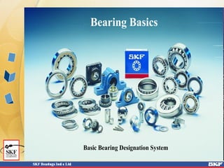
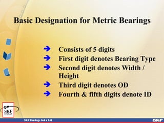
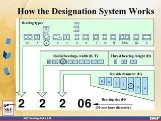
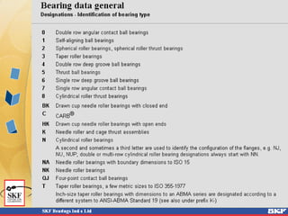
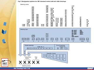
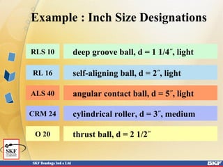
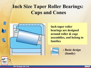
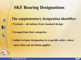
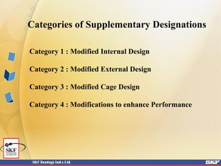
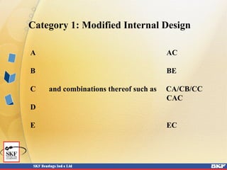
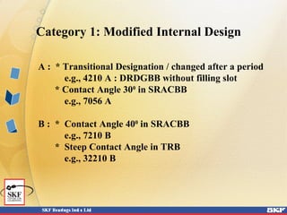
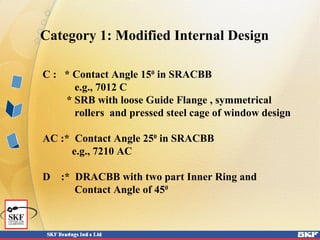
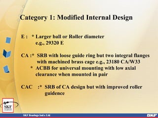
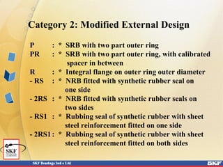
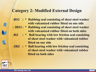
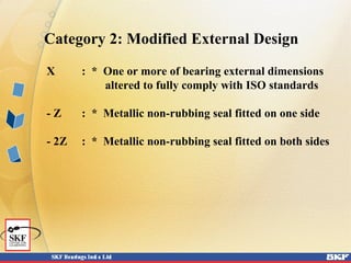
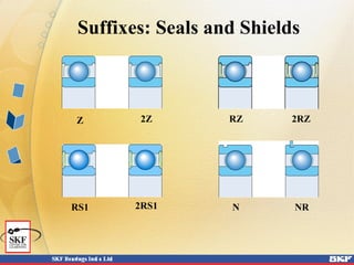
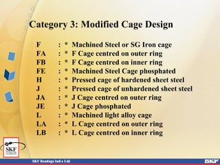
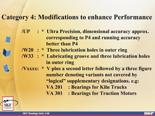
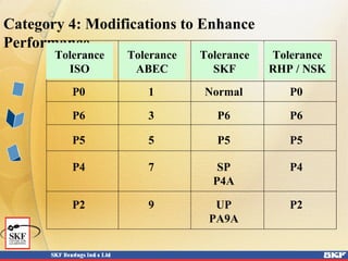
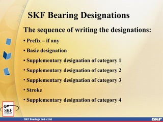
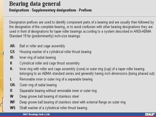
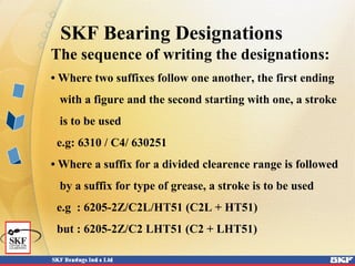
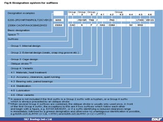
Bearing Basics
Basic Bearing Designation System
SKF Bearing Designations
Bearing Designations are of two types
 Basic Designations
 Supplementary Designations
The basic designation identifies:
• Product type
• Standard design
• Size
The supplementary designation identifies:
• Alternative design (variants)
• Bearing components
• Types of special bearings
SKF Bearing Designations
The Supplementary Designations identify
 Alternative Designs ( Variants )
 Bearing Components
 Type of Special Bearing
Supplementary designation consists of
 Prefixes
 Suffixes
Width and Diameter Variations
ISO Standards
International
Organization for
Standardization
ISOISO
Basic Designation for Metric Bearings
 Consists of 5 digits
 First digit denotes Bearing Type
 Second digit denotes Width /
Height
 Third digit denotes OD
 Fourth & fifth digits denote ID
Diameter Series
Relationship: Diameter and Width
Series
Dimension Series
Diameter Series
Width Series
Dimension Series
3
2
0
0 1 2 3
03
02
00
13
12
10
23
22
20 30
32
33
How the Designation System Works
Bearing types
Radial bearings, width (B, T) Thrust bearing, height (H)
Outside diameter (D)
Bearing size d/5
(30 mm bore diameter)
Bearing Type Designations:
Cylindrical Roller Bearings
NU NJ NUP
N NU + HJ NJ + HJ
Basic Series Designations:
Standard Inch Size Bearings
L L L L
Bearing
type
Bearing
series
Bore
1/8’s
of inch
Standard Inch Size Bearing Types
deep groove ball bearings
angular contact ball bearings
self-aligning ball bearings
cylindrical roller bearings
RLS RMS
ALS AMS
RL RM
CRL CRM
L: light series M: medium series
Example : Inch Size Designations
deep groove ball, d = 1 1/4˝, light
cylindrical roller, d = 3˝, medium
self-aligning ball, d = 2˝, light
angular contact ball, d = 5˝, light
RLS 10
CRM 24
RL 16
ALS 40
thrust ball, d = 2 1/2˝O 20
Inch Size Taper Roller Bearings:
Cups and Cones
Inch taper roller
bearings are designed
around roller & cage
assemblies, and belong to
families
: Basic design
(family)
The supplementary designation identifies:
• Variants – deviations from standard design
• Grouped into four categories
• Added to basic designation in a specific order, where
more than one deviation applies
SKF Bearing Designations
Categories of Supplementary Designations
Category 1 : Modified Internal Design
Category 2 : Modified External Design
Category 3 : Modified Cage Design
Category 4 : Modifications to enhance Performance
Category 1: Modified Internal Design
A AC
B BE
C and combinations thereof such as CA/CB/CC
CAC
D
E EC
Category 1: Modified Internal Design
A : * Transitional Designation / changed after a period
e.g., 4210 A : DRDGBB without filling slot
* Contact Angle 300
in SRACBB
e.g., 7056 A
B : * Contact Angle 400
in SRACBB
e.g., 7210 B
* Steep Contact Angle in TRB
e.g., 32210 B
Category 1: Modified Internal Design
C : * Contact Angle 150
in SRACBB
e.g., 7012 C
* SRB with loose Guide Flange , symmetrical
rollers and pressed steel cage of window design
AC :* Contact Angle 250
in SRACBB
e.g., 7210 AC
D :* DRACBB with two part Inner Ring and
Contact Angle of 450
Category 1: Modified Internal Design
E : * Larger ball or Roller diameter
e.g., 29320 E
CA :* SRB with loose guide ring but two integral flanges
with machined brass cage e.g., 23180 CA/W33
* ACBB for universal mounting with low axial
clearance when mounted in pair
CAC :* SRB of CA design but with improved roller
guidence
Category 1: Modified Internal Design
CB : * ACBB for universal mounting with axial
clearance larger than CA when mounted in pair
CC :* ACBB for universal mounting with axial
clearance larger than CB when mounted in pair
* SRB of C design but with improved roller
guidance
EC : * Single Row CRB with a greater number of
larger rollers than the original design, and
increased axial load carrying capacity in
Flanged executions
e.g., NU 320 EC / NJ 320 EC
Category 1: Modified Internal Design
GA : * ACBB for universal mounting with light
preload when mounted in pair
GB :* ACBB for universal mounting with axial
preload larger than GA when mounted in pair
GC : * ACBB for universal mounting with axial
preload larger than GB when mounted in pair
Category 2: Modified External Design
K : * Tapered Bore ( Taper 1 : 12 )
K 30 : * Tapered Bore ( Taper 1 : 30 )
N : * Snap ring groove on bearing outer diameter
N1 : * One locating slot on outside edge of outer ring
N2 : * Two diametrically opposite locating slots on
outside edge of outer ring
N4 : * N + N2. Locating slots on side opposite to
snap ring groove
N6 : * N + N2. Locating slots on same side as snap
ring groove
NR : * Snap ring groove on bearing outer diameter
along with an appropriate snap ring
Category 2: Modified External Design
Tapered Bore Suffixes
Suffix K
Suffix K30
Taper 1:12
Taper 1:30
Category 2: Modified External Design
P : * SRB with two part outer ring
PR : * SRB with two part outer ring, with calibrated
spacer in between
R : * Integral flange on outer ring outer diameter
- RS : * NRB fitted with synthetic rubber seal on
one side
- 2RS : * NRB fitted with synthetic rubber seals on
two sides
- RS1 : * Rubbing seal of synthetic rubber with sheet
steel reinforcement fitted on one side
- 2RS1: * Rubbing seal of synthetic rubber with sheet
steel reinforcement fitted on both sides
Category 2: Modified External Design
-RS2 : * Rubbing seal consisting of sheet steel washer
with vulcanized rubber fitted on one side
- 2RS1: * Rubbing seal consisting of sheet steel washer
with vulcanized rubber fitted on both sides
-RZ : * Ball bearing with low friction seal consisting
of sheet steel washer with vulcanized rubber
fitted on one side
-2RZ : * Ball bearing with low friction seal consisting
of sheet steel washer with vulcanized rubber
fitted on both sides
Category 2: Modified External Design
X : * One or more of bearing external dimensions
altered to fully comply with ISO standards
- Z : * Metallic non-rubbing seal fitted on one side
- 2Z : * Metallic non-rubbing seal fitted on both sides
Z RZ2Z
N
2RZ
NRRS1 2RS1
Suffixes: Seals and Shields
Category 3: Modified Cage Design
F : * Machined Steel or SG Iron cage
FA : * F Cage centred on outer ring
FB : * F Cage centred on inner ring
FE : * Machined Steel Cage phosphated
H : * Pressed cage of hardened sheet steel
J : * Pressed cage of unhardened sheet steel
JA : * J Cage centred on outer ring
JE : * J Cage phosphated
L : * Machined light alloy cage
LA : * L Cage centred on outer ring
LB : * L Cage centred on inner ring
Category 3: Modified Cage Design
Cage Types
Category 3: Modified Cage Design
M : * Machined Brass cage
MA : * M Cage centred on outer ring
MB : * M Cage centred on inner ring
MP : * M Cage window type
P : * Moulded cage made of glass fibre reinforced
polyamide 6.6
TN : * Moulded cage made of plastic
Y : * Pressed Brass cage
V : * Full complement bearing ( without cage )
Category 4: Modifications to enhance Performance
/CL7A: * Standard SKF quality for Pinion Bearings
/CL7C: * Special SKF quality for Pinion Bearings
/CN : * Normal internal clearance. This usually used
followed by H/M/L/P to denote part or
displaced range e.g.:
CNH : * Upper half of Normal
CNM : * Two middle quarters of Normal
CNL : * Lower half of Normal
CNP : * Upper half of Normal &
Lower half of C3
Category 4: Modifications to enhance Performance
/C1 : * Internal clearance less than C2
/C2 : * Internal clearance less than Normal
/C3 : * Internal clearance more than Normal
/C4 : * Internal clearance more than C3
/C5 : * Internal clearance more than C4
A letter H/M/L/P following the clearance
designation denotes part or displaced range.
/C01 : * Reduced tolerance for running accuracy of I/R
/C02 : * Extra reduced tolerance for running accuracy
of I/R : less than C01
Category 4: Modifications to Enhance
Performance
C1 clearance less than C2
C2 clearance less than Normal
C3 clearance greater than Normal
C4 clearance greater than C3
C5 clearance greater than C4
Radial internal
clearance
Axial internal
clearance
Suffix Range for Internal Clearances
Category 4: Modifications to enhance Performance
/C03 : * Reduced tolerance for running accuracy of O/R
/C04 : * Extra reduced tolerance for running accuracy
of O/R : less than C03
/C05 : * C01 + C03
/C06 : * C02 + C03
/C05 : * C01 + C04
/C06 : * C02 + C04
/C10 : * Reduced tolerance for bore & OD. In case of
tapered bore, refers to only OD.
/C20 : * Bore diameter tolerance less than C10
Category 4: Modifications to enhance Performance
/C30 : * Reduced bore diameter tolerance, towards
standard minimum limit.
/C40 : * OD tolerance less than C10
/C50 : * Reduced OD tolerance, towards standard
minimum limit.
/C60 : * C20 + C50
/C70 : * C20 + C40
/C80 : * Reduced height tolerance for thrust bearings
/C15 : * C10 + C05
/C18 : * C10 + C08
/C78 : * C70 + C08
Category 4: Modifications to enhance Performance
/DB : * Two single row DGBB/ACBB/TRB, paired
for mounting in back-to-back arrangement.
/DF : * Two single row DGBB/ACBB/TRB, paired
for mounting in face-to-face arrangement.
/DT : * Two single row DGBB/ACBB/TRB, paired
for mounting in tandem
/HA : * Case hardened bearing or bearing components.
For closer identification, it is followed by one of
following numbers : 0/1/2/3/4/5/6/7 e.g.,
1 Both rings
2 Outer ring
5 Rolling elements etc.
Category 4: Modifications to enhance Performance
/HT : * Bearing supplied with High Temperature
( upto +1300
C) grease
/LHT : * Bearing supplied with Low as well as High
Temperature ( -40 to +1400
C) grease
/LT : * Bearing supplied with Low Temperature
( upto -500
C) grease
/MT : * Bearing supplied with Medium Temperature
( -30 to +1100
C) grease
Category 4: Modifications to enhance Performance
/P4 : * Dimensional and running accuracy to ISO
tolerance class 4.
/P4A : * Dimensional accuracy to ISO tolerance class 4
and and running accuracy to AFBMA class 9.
/P5 : * Dimensional and running accuracy to ISO
tolerance class 5 ( More accurate than P6).
/P6 : * Dimensional and running accuracy to ISO
tolerance class 6.
/P43 : * P4 + C3
/P52 : * P5 + C2
/P62 : * P6 + C2
/PA9 : * Dimensional and running accuracy to AFBMA
class 9.
Category 4: Modifications to enhance Performance
/SP : * Special Precision, dimensional accuracy approx.
corresponding to P5 and running accuracy
approx. to P4
/S0 : * Bearing ring dimensionally stabilized to optg.
temperatures upto + 1500
C
/S1 : * Bearing ring dimensionally stabilized to optg.
temperatures upto + 2000
C
/S2 : * Bearing ring dimensionally stabilized to optg.
temperatures upto + 2500
C
/S3 : * Bearing ring dimensionally stabilized to optg.
temperatures upto + 3000
C
/S4 : * Bearing ring dimensionally stabilized to optg.
temperatures upto + 3500
C
Category 4: Modifications to enhance Performance
/UP : * Ultra Precision, dimensional accuracy approx.
corresponding to P4 and running accuracy
better than P4
/W20 : * Three lubrication holes in outer ring
/W33 : * Lubricating groove and three lubrication holes
in outer ring
/Vxxxx: * V plus a second letter followed by a three figure
number denoting variants not covered by
“logical” supplementary designations. e.g:
VA 201 : Bearings for Kiln Trucks
VA 301 : Bearings for Traction Motors
Category 4: Modifications to Enhance
Performance
P0 1 Normal P0
P6 3 P6 P6
P5 5 P5 P5
P4 7 SP P4
P4A
P2 9 UP P2
PA9A
Tolerance
ISO
Tolerance
ABEC
Tolerance
SKF
Tolerance
RHP / NSK
SKF Bearing Designations
The sequence of writing the designations:
• Prefix – if any
• Basic designation
• Supplementary designation of category 1
• Supplementary designation of category 2
• Supplementary designation of category 3
• Stroke
• Supplementary designation of category 4
SKF Bearing Designations
The sequence of writing the designations:
• Where two suffixes follow one another, the first ending
with a figure and the second starting with one, a stroke
is to be used
e.g: 6310 / C4/ 630251
• Where a suffix for a divided clearence range is followed
by a suffix for type of grease, a stroke is to be used
e.g : 6205-2Z/C2L/HT51 (C2L + HT51)
but : 6205-2Z/C2 LHT51 (C2 + LHT51)
Letter Year Year Year Year Letter Year Year Year Year
A 1910 1934 1958 1981 N 1922 1946 1970 1993
B 1911 1935 1959 1982 O 1923 1947 1971 1994
C 1912 1936 1960 1983 P 1924 1948 1972 1995
D 1913 1937 1961 1984 R 1925 1949 1973 1996
E 1914 1938 1962 1985 S 1926 1950 1974 1997
F 1915 1939 1963 1986 T 1927 1951 1975 1998
G 1916 1940 1964 1987 U 1928 1952 1976 1999
E 1917 1941 1965 1988 V 1929 1953 – –
J 1918 1942 1966 1989 W 1930 1954 1977 2000
K 1919 1943 1967 1990 X 1931 1955 1978 2001
L 1920 1944 1968 1991 Y 1932 1956 1979 2002
M 1921 1945 1969 1992 Z 1933 1957 1980 2003
Date Codes
The Year Letter to be marked on a bearing or a bearing accessory shall
comprise a single letter in accordance with the table below

1.3 bearing designation system

  • 1.
    Bearing Basics Basic BearingDesignation System
  • 2.
  • 3.
    Bearing Designations areof two types  Basic Designations  Supplementary Designations
  • 4.
    The basic designationidentifies: • Product type • Standard design • Size The supplementary designation identifies: • Alternative design (variants) • Bearing components • Types of special bearings SKF Bearing Designations
  • 5.
    The Supplementary Designationsidentify  Alternative Designs ( Variants )  Bearing Components  Type of Special Bearing Supplementary designation consists of  Prefixes  Suffixes
  • 6.
  • 7.
  • 8.
    Basic Designation forMetric Bearings  Consists of 5 digits  First digit denotes Bearing Type  Second digit denotes Width / Height  Third digit denotes OD  Fourth & fifth digits denote ID
  • 9.
  • 10.
  • 11.
    Dimension Series Diameter Series WidthSeries Dimension Series 3 2 0 0 1 2 3 03 02 00 13 12 10 23 22 20 30 32 33
  • 12.
    How the DesignationSystem Works Bearing types Radial bearings, width (B, T) Thrust bearing, height (H) Outside diameter (D) Bearing size d/5 (30 mm bore diameter)
  • 15.
    Bearing Type Designations: CylindricalRoller Bearings NU NJ NUP N NU + HJ NJ + HJ
  • 16.
    Basic Series Designations: StandardInch Size Bearings L L L L Bearing type Bearing series Bore 1/8’s of inch
  • 17.
    Standard Inch SizeBearing Types deep groove ball bearings angular contact ball bearings self-aligning ball bearings cylindrical roller bearings RLS RMS ALS AMS RL RM CRL CRM L: light series M: medium series
  • 18.
    Example : InchSize Designations deep groove ball, d = 1 1/4˝, light cylindrical roller, d = 3˝, medium self-aligning ball, d = 2˝, light angular contact ball, d = 5˝, light RLS 10 CRM 24 RL 16 ALS 40 thrust ball, d = 2 1/2˝O 20
  • 19.
    Inch Size TaperRoller Bearings: Cups and Cones Inch taper roller bearings are designed around roller & cage assemblies, and belong to families : Basic design (family)
  • 20.
    The supplementary designationidentifies: • Variants – deviations from standard design • Grouped into four categories • Added to basic designation in a specific order, where more than one deviation applies SKF Bearing Designations
  • 21.
    Categories of SupplementaryDesignations Category 1 : Modified Internal Design Category 2 : Modified External Design Category 3 : Modified Cage Design Category 4 : Modifications to enhance Performance
  • 22.
    Category 1: ModifiedInternal Design A AC B BE C and combinations thereof such as CA/CB/CC CAC D E EC
  • 23.
    Category 1: ModifiedInternal Design A : * Transitional Designation / changed after a period e.g., 4210 A : DRDGBB without filling slot * Contact Angle 300 in SRACBB e.g., 7056 A B : * Contact Angle 400 in SRACBB e.g., 7210 B * Steep Contact Angle in TRB e.g., 32210 B
  • 24.
    Category 1: ModifiedInternal Design C : * Contact Angle 150 in SRACBB e.g., 7012 C * SRB with loose Guide Flange , symmetrical rollers and pressed steel cage of window design AC :* Contact Angle 250 in SRACBB e.g., 7210 AC D :* DRACBB with two part Inner Ring and Contact Angle of 450
  • 25.
    Category 1: ModifiedInternal Design E : * Larger ball or Roller diameter e.g., 29320 E CA :* SRB with loose guide ring but two integral flanges with machined brass cage e.g., 23180 CA/W33 * ACBB for universal mounting with low axial clearance when mounted in pair CAC :* SRB of CA design but with improved roller guidence
  • 26.
    Category 1: ModifiedInternal Design CB : * ACBB for universal mounting with axial clearance larger than CA when mounted in pair CC :* ACBB for universal mounting with axial clearance larger than CB when mounted in pair * SRB of C design but with improved roller guidance EC : * Single Row CRB with a greater number of larger rollers than the original design, and increased axial load carrying capacity in Flanged executions e.g., NU 320 EC / NJ 320 EC
  • 27.
    Category 1: ModifiedInternal Design GA : * ACBB for universal mounting with light preload when mounted in pair GB :* ACBB for universal mounting with axial preload larger than GA when mounted in pair GC : * ACBB for universal mounting with axial preload larger than GB when mounted in pair
  • 28.
    Category 2: ModifiedExternal Design K : * Tapered Bore ( Taper 1 : 12 ) K 30 : * Tapered Bore ( Taper 1 : 30 ) N : * Snap ring groove on bearing outer diameter N1 : * One locating slot on outside edge of outer ring N2 : * Two diametrically opposite locating slots on outside edge of outer ring N4 : * N + N2. Locating slots on side opposite to snap ring groove N6 : * N + N2. Locating slots on same side as snap ring groove NR : * Snap ring groove on bearing outer diameter along with an appropriate snap ring
  • 29.
    Category 2: ModifiedExternal Design Tapered Bore Suffixes Suffix K Suffix K30 Taper 1:12 Taper 1:30
  • 30.
    Category 2: ModifiedExternal Design P : * SRB with two part outer ring PR : * SRB with two part outer ring, with calibrated spacer in between R : * Integral flange on outer ring outer diameter - RS : * NRB fitted with synthetic rubber seal on one side - 2RS : * NRB fitted with synthetic rubber seals on two sides - RS1 : * Rubbing seal of synthetic rubber with sheet steel reinforcement fitted on one side - 2RS1: * Rubbing seal of synthetic rubber with sheet steel reinforcement fitted on both sides
  • 31.
    Category 2: ModifiedExternal Design -RS2 : * Rubbing seal consisting of sheet steel washer with vulcanized rubber fitted on one side - 2RS1: * Rubbing seal consisting of sheet steel washer with vulcanized rubber fitted on both sides -RZ : * Ball bearing with low friction seal consisting of sheet steel washer with vulcanized rubber fitted on one side -2RZ : * Ball bearing with low friction seal consisting of sheet steel washer with vulcanized rubber fitted on both sides
  • 32.
    Category 2: ModifiedExternal Design X : * One or more of bearing external dimensions altered to fully comply with ISO standards - Z : * Metallic non-rubbing seal fitted on one side - 2Z : * Metallic non-rubbing seal fitted on both sides
  • 33.
  • 34.
    Category 3: ModifiedCage Design F : * Machined Steel or SG Iron cage FA : * F Cage centred on outer ring FB : * F Cage centred on inner ring FE : * Machined Steel Cage phosphated H : * Pressed cage of hardened sheet steel J : * Pressed cage of unhardened sheet steel JA : * J Cage centred on outer ring JE : * J Cage phosphated L : * Machined light alloy cage LA : * L Cage centred on outer ring LB : * L Cage centred on inner ring
  • 35.
    Category 3: ModifiedCage Design Cage Types
  • 36.
    Category 3: ModifiedCage Design M : * Machined Brass cage MA : * M Cage centred on outer ring MB : * M Cage centred on inner ring MP : * M Cage window type P : * Moulded cage made of glass fibre reinforced polyamide 6.6 TN : * Moulded cage made of plastic Y : * Pressed Brass cage V : * Full complement bearing ( without cage )
  • 37.
    Category 4: Modificationsto enhance Performance /CL7A: * Standard SKF quality for Pinion Bearings /CL7C: * Special SKF quality for Pinion Bearings /CN : * Normal internal clearance. This usually used followed by H/M/L/P to denote part or displaced range e.g.: CNH : * Upper half of Normal CNM : * Two middle quarters of Normal CNL : * Lower half of Normal CNP : * Upper half of Normal & Lower half of C3
  • 38.
    Category 4: Modificationsto enhance Performance /C1 : * Internal clearance less than C2 /C2 : * Internal clearance less than Normal /C3 : * Internal clearance more than Normal /C4 : * Internal clearance more than C3 /C5 : * Internal clearance more than C4 A letter H/M/L/P following the clearance designation denotes part or displaced range. /C01 : * Reduced tolerance for running accuracy of I/R /C02 : * Extra reduced tolerance for running accuracy of I/R : less than C01
  • 39.
    Category 4: Modificationsto Enhance Performance C1 clearance less than C2 C2 clearance less than Normal C3 clearance greater than Normal C4 clearance greater than C3 C5 clearance greater than C4 Radial internal clearance Axial internal clearance Suffix Range for Internal Clearances
  • 40.
    Category 4: Modificationsto enhance Performance /C03 : * Reduced tolerance for running accuracy of O/R /C04 : * Extra reduced tolerance for running accuracy of O/R : less than C03 /C05 : * C01 + C03 /C06 : * C02 + C03 /C05 : * C01 + C04 /C06 : * C02 + C04 /C10 : * Reduced tolerance for bore & OD. In case of tapered bore, refers to only OD. /C20 : * Bore diameter tolerance less than C10
  • 41.
    Category 4: Modificationsto enhance Performance /C30 : * Reduced bore diameter tolerance, towards standard minimum limit. /C40 : * OD tolerance less than C10 /C50 : * Reduced OD tolerance, towards standard minimum limit. /C60 : * C20 + C50 /C70 : * C20 + C40 /C80 : * Reduced height tolerance for thrust bearings /C15 : * C10 + C05 /C18 : * C10 + C08 /C78 : * C70 + C08
  • 42.
    Category 4: Modificationsto enhance Performance /DB : * Two single row DGBB/ACBB/TRB, paired for mounting in back-to-back arrangement. /DF : * Two single row DGBB/ACBB/TRB, paired for mounting in face-to-face arrangement. /DT : * Two single row DGBB/ACBB/TRB, paired for mounting in tandem /HA : * Case hardened bearing or bearing components. For closer identification, it is followed by one of following numbers : 0/1/2/3/4/5/6/7 e.g., 1 Both rings 2 Outer ring 5 Rolling elements etc.
  • 43.
    Category 4: Modificationsto enhance Performance /HT : * Bearing supplied with High Temperature ( upto +1300 C) grease /LHT : * Bearing supplied with Low as well as High Temperature ( -40 to +1400 C) grease /LT : * Bearing supplied with Low Temperature ( upto -500 C) grease /MT : * Bearing supplied with Medium Temperature ( -30 to +1100 C) grease
  • 44.
    Category 4: Modificationsto enhance Performance /P4 : * Dimensional and running accuracy to ISO tolerance class 4. /P4A : * Dimensional accuracy to ISO tolerance class 4 and and running accuracy to AFBMA class 9. /P5 : * Dimensional and running accuracy to ISO tolerance class 5 ( More accurate than P6). /P6 : * Dimensional and running accuracy to ISO tolerance class 6. /P43 : * P4 + C3 /P52 : * P5 + C2 /P62 : * P6 + C2 /PA9 : * Dimensional and running accuracy to AFBMA class 9.
  • 45.
    Category 4: Modificationsto enhance Performance /SP : * Special Precision, dimensional accuracy approx. corresponding to P5 and running accuracy approx. to P4 /S0 : * Bearing ring dimensionally stabilized to optg. temperatures upto + 1500 C /S1 : * Bearing ring dimensionally stabilized to optg. temperatures upto + 2000 C /S2 : * Bearing ring dimensionally stabilized to optg. temperatures upto + 2500 C /S3 : * Bearing ring dimensionally stabilized to optg. temperatures upto + 3000 C /S4 : * Bearing ring dimensionally stabilized to optg. temperatures upto + 3500 C
  • 46.
    Category 4: Modificationsto enhance Performance /UP : * Ultra Precision, dimensional accuracy approx. corresponding to P4 and running accuracy better than P4 /W20 : * Three lubrication holes in outer ring /W33 : * Lubricating groove and three lubrication holes in outer ring /Vxxxx: * V plus a second letter followed by a three figure number denoting variants not covered by “logical” supplementary designations. e.g: VA 201 : Bearings for Kiln Trucks VA 301 : Bearings for Traction Motors
  • 47.
    Category 4: Modificationsto Enhance Performance P0 1 Normal P0 P6 3 P6 P6 P5 5 P5 P5 P4 7 SP P4 P4A P2 9 UP P2 PA9A Tolerance ISO Tolerance ABEC Tolerance SKF Tolerance RHP / NSK
  • 48.
    SKF Bearing Designations Thesequence of writing the designations: • Prefix – if any • Basic designation • Supplementary designation of category 1 • Supplementary designation of category 2 • Supplementary designation of category 3 • Stroke • Supplementary designation of category 4
  • 49.
  • 50.
    SKF Bearing Designations Thesequence of writing the designations: • Where two suffixes follow one another, the first ending with a figure and the second starting with one, a stroke is to be used e.g: 6310 / C4/ 630251 • Where a suffix for a divided clearence range is followed by a suffix for type of grease, a stroke is to be used e.g : 6205-2Z/C2L/HT51 (C2L + HT51) but : 6205-2Z/C2 LHT51 (C2 + LHT51)
  • 52.
    Letter Year YearYear Year Letter Year Year Year Year A 1910 1934 1958 1981 N 1922 1946 1970 1993 B 1911 1935 1959 1982 O 1923 1947 1971 1994 C 1912 1936 1960 1983 P 1924 1948 1972 1995 D 1913 1937 1961 1984 R 1925 1949 1973 1996 E 1914 1938 1962 1985 S 1926 1950 1974 1997 F 1915 1939 1963 1986 T 1927 1951 1975 1998 G 1916 1940 1964 1987 U 1928 1952 1976 1999 E 1917 1941 1965 1988 V 1929 1953 – – J 1918 1942 1966 1989 W 1930 1954 1977 2000 K 1919 1943 1967 1990 X 1931 1955 1978 2001 L 1920 1944 1968 1991 Y 1932 1956 1979 2002 M 1921 1945 1969 1992 Z 1933 1957 1980 2003 Date Codes The Year Letter to be marked on a bearing or a bearing accessory shall comprise a single letter in accordance with the table below