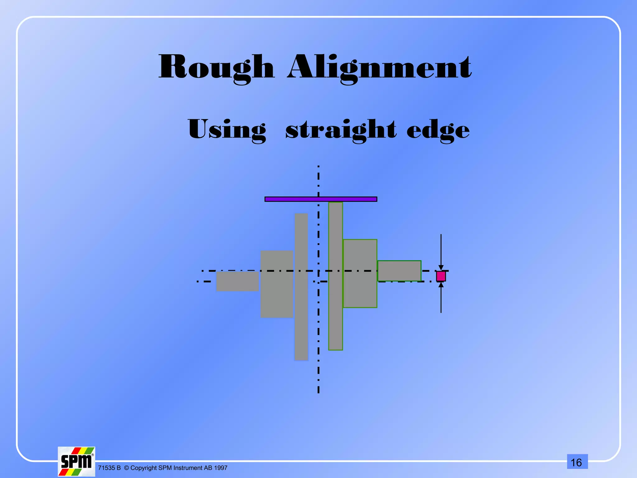
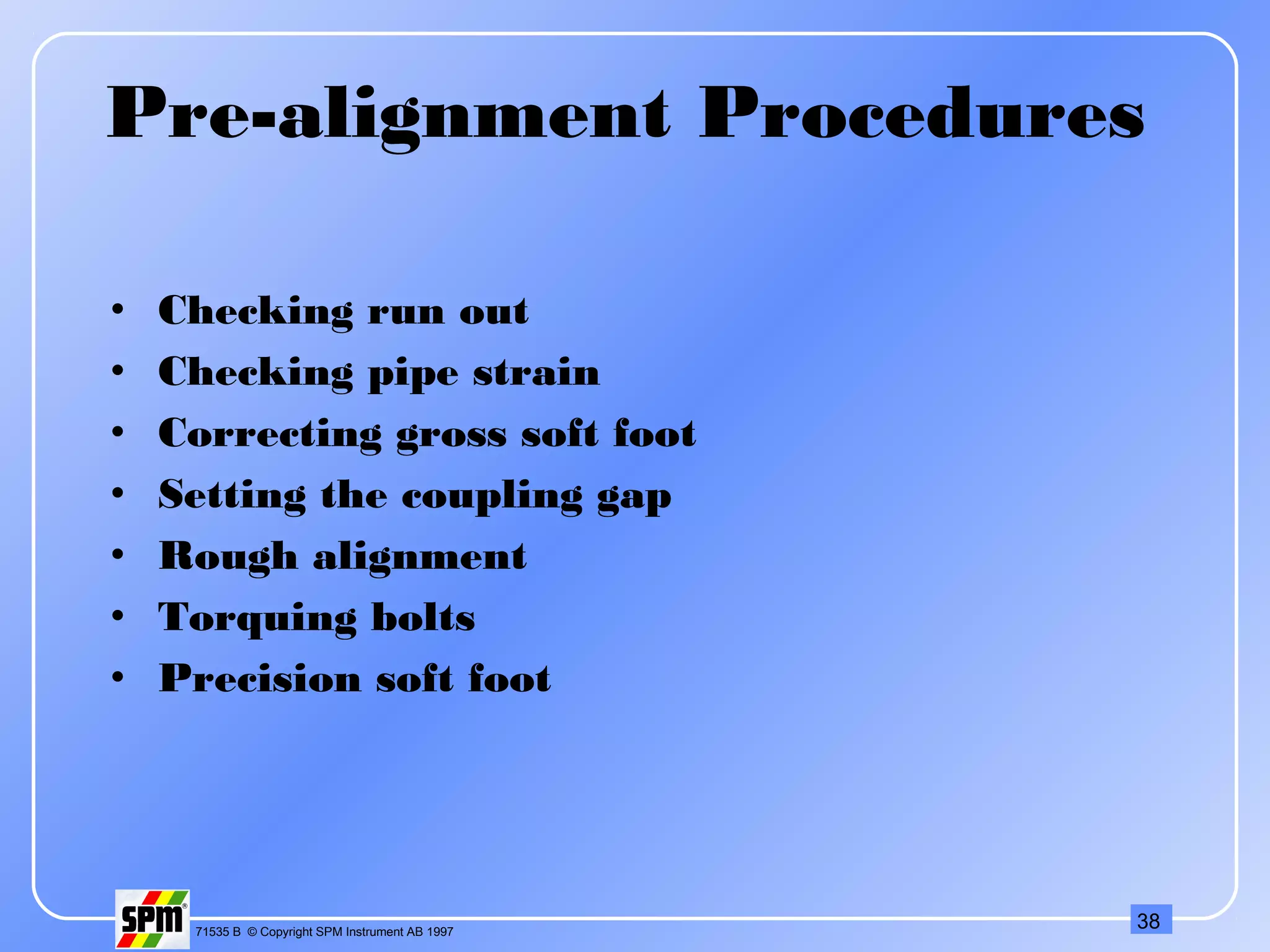
171535 B © Copyright SPM Instrument AB 1997
Training Program
On
Machine
Alignment
271535 B © Copyright SPM Instrument AB 1997
What is Alignment?
It is the process of positioning two (or more) machines
that are coupled, so that Center lines of rotating
shafts form a single line when the machines are
working at normal operating temperature.
371535 B © Copyright SPM Instrument AB 1997
Types Of Misalignment
1. Off set
2. Angular
3. Skew - Combination of offset &
angular
471535 B © Copyright SPM Instrument AB 1997
Offset Misalignment
571535 B © Copyright SPM Instrument AB 1997
Angular Misalignment
671535 B © Copyright SPM Instrument AB 1997
Skewed Misalignment
771535 B © Copyright SPM Instrument AB 1997
Causes Of Misalignment
Thermal expansion - Most machines align cold.
 Forces transmitted to the machine by pipe or
support structure.
Soft foot.
 Poor workmanship.
871535 B © Copyright SPM Instrument AB 1997
Effects Of Misalignment
More than 50% problems are due to
misalignment.
Causes vibration on the machine
Vibration destroys critical parts of machines
like bearings, gears, seals, coupling etc.
Breaks lubricant film inside the bearing and
increase friction.
Increases load on the bearing.
Increase 2 - 17% power consumption.
Generates heat inside the coupling.
971535 B © Copyright SPM Instrument AB 1997
Recognition of Misalignment
1. Excessive Radial & Axial vibration
2. Premature / repetitive failure of bearing, seal, coupling.
3. Loose coupling elements.
4. Leakage from the seal.
5. Loose base bolts.
6. Coupling become hot while running.
7. High casing temperature.
1071535 B © Copyright SPM Instrument AB 1997
Scientific
Diagnosis of Misalignment
1. Vibration Spectrum Analysis
2. Vibration Phase Analysis
3. Wear Particle Analysis
1171535 B © Copyright SPM Instrument AB 1997
Angular - Axial vibration at 1X RPM
Offset - Radial vibration at 2X or 3X RPM
Harmonics (3X-10X) generates as severity
increases.
•If the 2X amplitude more than 50% of 1X then
coupling damage starts.
•If the 2X amplitude more than 150% of 1X then
machine should be stopped for correction.
1. Vibration Spectrum Analysis
1271535 B © Copyright SPM Instrument AB 1997
Angular - 1800
phase shift in the axial direction
across the coupling.
Offset - 1800
phase shift in the radial direction
across the coupling. 00
to 1800
phase shift occur
as the sensor moves from horizontal to the
vertical direction of the same machine.
Skew - 1800
phase shift in the axial or radial
direction across the coupling.
2. Vibration Phase Analysis
1371535 B © Copyright SPM Instrument AB 1997
3. Wear Particle Analysis
Curly cutting wear particle of 5:1 to 50:1 aspect
ratio.
1471535 B © Copyright SPM Instrument AB 1997
Flexible Coupling
•Flexible coupling can handle some
misalignment but it will generate heat and it
will impose forces to the shafts.
•This will create vibrations,
and couplings, seals and bearings will fail
prematurely.
•A flexible coupling is however, necessary to
handle the movement from cold to hot
condition.
1571535 B © Copyright SPM Instrument AB 1997
Alignment Methods
1. Rough Alignment
• Using straight edge,
Ruler, Feeler Gauge
• Twin wire method
2. Precision Alignment
• Using dial gauges
• Using Lasers
1671535 B © Copyright SPM Instrument AB 1997
Using straight edge
Rough Alignment
1771535 B © Copyright SPM Instrument AB 1997
Using twin wire
Rough Alignment
1871535 B © Copyright SPM Instrument AB 1997
•Measure the coupling gap at the top & bottom.
•Find the difference
•Gap difference = widest gap - narrowest gap
Rough Alignment: Vertical
Angular
If the gap is wider at the top, correct angular
misalignment by removing shims from front feet
or by adding to the rear feet.. If the gap is wider
at the bottom, remove shims from the rear feet or
add to the front feet.
1971535 B © Copyright SPM Instrument AB 1997
Rough Alignment: Vertical
Angular
2071535 B © Copyright SPM Instrument AB 1997
•You will solve horizontal angular
misalignment and then horizontal offset
misalignment.
•Repeat the process you performed vertically
only this time measure in the horizontal
axis.
Rough Alignment:
Horizontal Corrections
2171535 B © Copyright SPM Instrument AB 1997
Face & Rim Method
2271535 B © Copyright SPM Instrument AB 1997
Face Readings
-ve
Dial Readings
-ve
-ve
-ve
+ve
+ve
+ve
+ve
Dial on SM Dial on MM
Dial Readings
2371535 B © Copyright SPM Instrument AB 1997
Face & Rim Method
Advantages:
. Good for large dia. coupling hubs where the shafts are close together.
. To be used where one of the shafts can not rotate during alignment.
. Easy to use.
Disadvantages:
1. Difficult to take face readings, if there is axial float in
the shaft.
2. Requires removal of coupling spool.
3. More complex alignment calculation.
2471535 B © Copyright SPM Instrument AB 1997
Reverse Indicator Method
2571535 B © Copyright SPM Instrument AB 1997
Reverse Indicator Method
Advantages:
1. More accurate than face & rim
method.
2. Readings are not affected by axial
float.
3. Possible to keep the coupling spool.
Disadvantages:
1. Should not be used on close coupled shafts.
2. Difficult to take readings on long shaft.
2671535 B © Copyright SPM Instrument AB 1997
L
D/
2
Which Method To Be Used?
If L > D Reverse Indicator
2771535 B © Copyright SPM Instrument AB 1997
Calculation can be
made for each of the
method to verify the
readings.
Combination Method
2871535 B © Copyright SPM Instrument AB 1997
Off Set Angular
RPM mm mm / 100 mm
0000 - 1000 0.13 0.10
1000 - 2000 0.10 0.08
2000 - 3000 0.07 0.07
3000 - 4000 0.05 0.06
4000 - 5000 0.03 0.05
5000 - 6000 < 0.03 0.04
Alignment
Tolerance
(acceptable)
2971535 B © Copyright SPM Instrument AB 1997
Off Set Angular
RPM mm mm / 100 mm
0000 - 1000 0.07 0.06
1000 - 2000 0.05 0.05
2000 - 3000 0.03 0.04
3000 - 4000 0.02 0.03
4000 - 5000 0.01 0.02
5000 - 6000 < 0.01 0.01
Alignment
Tolerance
(excellent)
3071535 B © Copyright SPM Instrument AB 1997
Disadvantages Of Dial
Indicator Method
More time consuming.
Too much manual work.
Indicator sag.
Difficult to perform on long shaft.
Difficult to determine soft foot.
Difficult to perform vertical shaft alignment.
3171535 B © Copyright SPM Instrument AB 1997
Indicator Sag
3271535 B © Copyright SPM Instrument AB 1997
Perpendicular to
the coupling
surface.
Fixing Of Dial Gauge
3371535 B © Copyright SPM Instrument AB 1997
Rules For Good Alignment
Clean the machine base. Remove rust burrs
etc.
Use steel or brass shims.
Check indicator sag.
Perform pre-alignment checks on Machine.
Check dial gauges before taking readings.
Use correct bolt tightening procedure.
Don’t lift the machine more than necessary.
Try to put the stem of dial gauge
perpendicular to
the surface of coupling.
Use jack bolts.
3471535 B © Copyright SPM Instrument AB 1997
Graphical representation
3571535 B © Copyright SPM Instrument AB 1997
Stationery Machine Movable Machine
+
+
Graphical representation
3671535 B © Copyright SPM Instrument AB 1997
Graphical representation
Example 1
(Reverse Indicator Method)
SM Dial Reading: -1.50 mm
MM Dial Reading : +0.5 mm
Scale: Y-axis = 10:1
X-axis = 1: 5
3771535 B © Copyright SPM Instrument AB 1997
Pre-alignment objectives
Pre-alignment Checks
The Secret to Fast Alignment
•Reduces errors
•Reduces re-work
•Machines maintain alignment position
•Simplifies the alignment procedure
•Check and correct situations that effect
machinery performance.
•Check and correct situations which cause
problems in executing the precision alignment
process
3871535 B © Copyright SPM Instrument AB 1997
Pre-alignment Procedures
• Checking run out
• Checking pipe strain
• Correcting gross soft foot
• Setting the coupling gap
• Rough alignment
• Torquing bolts
• Precision soft foot
3971535 B © Copyright SPM Instrument AB 1997
Run Out
Run out is caused by:
• Eccentric couplings
• “Out of round” couplings (Coupling hub bored off centre
or Coupling hub skew bored)
• Bent shafts
These problems cause imbalance and misalignment
forces. Results: Increased vibration, increased
energy dissipation, energy consumption and
reduced bearing life.
4071535 B © Copyright SPM Instrument AB 1997
Checking Run Out
• You check run out with a dial indicator.
• The dial indicator is affixed with a magnetic base
or a clamp.
• If the coupling is assembled, mount to the
machine base or to an adjacent machine.
4171535 B © Copyright SPM Instrument AB 1997
Checking Run Out
• The shaft to be checked is rotated when checking
run out.
• Rotate slowly until the indicator reaches a
maximum +/-.
• Zero the indicator.
• Rotate again until the indicator reaches a
maximum +/-.
4271535 B © Copyright SPM Instrument AB 1997
Pipe Strain
• Pipe strain is caused by pipes and flanges which
are misaligned.
• Pipe strain causes distortion of the driven
machine which results in bearing & seal
misalignment.
• Pipe strain will effect the alignment process if the
“stationary” machine is moved.
4371535 B © Copyright SPM Instrument AB 1997
Checking Pipe Strain
• The effect of pipe strain can be checked using a
dial indicator while the flange is loosened.
4471535 B © Copyright SPM Instrument AB 1997
Soft Foot
• A soft foot is caused when the four motor feet
or the four base pads are not in a common flat
plane.
4571535 B © Copyright SPM Instrument AB 1997
Soft Foot
• This condition is illustrated by placing shims
only at three feet.
4671535 B © Copyright SPM Instrument AB 1997
Soft Foot
•This condition will effect the alignment process
because vertical positions will not be repeatable
as you try to make corrections.
•Soft foot causes the motor frame to distort when
the bolts are tight.
• This condition results in bearing misalignment.
4771535 B © Copyright SPM Instrument AB 1997
•One type of soft foot is called “short foot”.
Soft Foot
4871535 B © Copyright SPM Instrument AB 1997
Soft Foot
•The problem is solved by adding shims to the
short foot.
4971535 B © Copyright SPM Instrument AB 1997
Soft Foot
•A second type of soft foot occurs as “angled foot”.
5071535 B © Copyright SPM Instrument AB 1997
•The problem can not solved by adding shims to
the short foot.
• You must correct the angle in this case.
Soft Foot
5171535 B © Copyright SPM Instrument AB 1997
Checking Soft Foot
•In this activity, you only check and correct “gross”
soft foot
•Start with all of the bolts loose.
•If there are no shims under the feet:
check for gross soft foot by trying to slip a .005”
shim
under each foot.
•If shims are under the feet::
check if any of the shims are loose.
5271535 B © Copyright SPM Instrument AB 1997
Soft Foot
5371535 B © Copyright SPM Instrument AB 1997
•An improper coupling gap causes excessive axial
forces which result in increased bearing load.
•Improper gap can also cause destruction of an
electric motor with plain bearings.
•The coupling gap should be set to the
manufacturer’s specification (to take care of
thermal expansion in axial direction).
Coupling Gap
5471535 B © Copyright SPM Instrument AB 1997
•Electric motors with plain bearings have endplay.
•Therefore, you must position the motor shaft at
magnetic centre before setting the coupling gap.
Coupling Gap
5571535 B © Copyright SPM Instrument AB 1997
•You check the coupling gap with a scale, feeler
gauge, taper gauge, or an inside micrometer.
•Move the motor axially to set the proper gap.
Setting the Coupling Gap
5671535 B © Copyright SPM Instrument AB 1997
•You will loosen and re-tighten the bolts several
times during the alignment process.
•Bolts should always be tightened in a known
sequence so that vertical positions are repeated as
you re-tighten the bolts.
Tightening Hold Down Bolts:
5771535 B © Copyright SPM Instrument AB 1997
Large expansion Small expansion
Thermal expansion
Intentional misalignment for cold machines
Proper alignment at operating temperature
5871535 B © Copyright SPM Instrument AB 1997
Laser Alignment
5971535 B © Copyright SPM Instrument AB 1997
Light Amplified By Stimulated Emission Of Radiation
Laser was originally emitted by charge sent
through
a gas mixture of Helium & Neon.
Now it is generated by a low power semi
conductor diode with collimating lenses.
Modulated to avoid interference from other
light
source
It is collinear.
Single wave length of 670 nm.
Class II Laser is used for Laser Alignment
Laser
6071535 B © Copyright SPM Instrument AB 1997
Laser Alignment
Advantages:
1. Easy to use.
2. Use Reverse Indicator Method.
3. Machine does the calculations.
4. 0 - 20m max. working distance.
5. Selectable high resolution 0.1, 0.01, 0.001mm.
6. No indicator sag.
7. Soft foot measurement program.
8. Horizontal shaft alignment with mim 600
rotation.
9. Vertical shaft alignment program.
6171535 B © Copyright SPM Instrument AB 1997
10.Thermal or offset compensation.
11. Machine train alignment program.
12. Cardon shaft alignment.
13. Straightness, Flatness,
Perpendicularly,
Parallelism measurement.
14. Spindle alignment.
15. Static feet correction.
16. Continuos monitoring.
6271535 B © Copyright SPM Instrument AB 1997

188757055 1-alignment

  • 1.
    171535 B ©Copyright SPM Instrument AB 1997 Training Program On Machine Alignment
  • 2.
    271535 B ©Copyright SPM Instrument AB 1997 What is Alignment? It is the process of positioning two (or more) machines that are coupled, so that Center lines of rotating shafts form a single line when the machines are working at normal operating temperature.
  • 3.
    371535 B ©Copyright SPM Instrument AB 1997 Types Of Misalignment 1. Off set 2. Angular 3. Skew - Combination of offset & angular
  • 4.
    471535 B ©Copyright SPM Instrument AB 1997 Offset Misalignment
  • 5.
    571535 B ©Copyright SPM Instrument AB 1997 Angular Misalignment
  • 6.
    671535 B ©Copyright SPM Instrument AB 1997 Skewed Misalignment
  • 7.
    771535 B ©Copyright SPM Instrument AB 1997 Causes Of Misalignment Thermal expansion - Most machines align cold.  Forces transmitted to the machine by pipe or support structure. Soft foot.  Poor workmanship.
  • 8.
    871535 B ©Copyright SPM Instrument AB 1997 Effects Of Misalignment More than 50% problems are due to misalignment. Causes vibration on the machine Vibration destroys critical parts of machines like bearings, gears, seals, coupling etc. Breaks lubricant film inside the bearing and increase friction. Increases load on the bearing. Increase 2 - 17% power consumption. Generates heat inside the coupling.
  • 9.
    971535 B ©Copyright SPM Instrument AB 1997 Recognition of Misalignment 1. Excessive Radial & Axial vibration 2. Premature / repetitive failure of bearing, seal, coupling. 3. Loose coupling elements. 4. Leakage from the seal. 5. Loose base bolts. 6. Coupling become hot while running. 7. High casing temperature.
  • 10.
    1071535 B ©Copyright SPM Instrument AB 1997 Scientific Diagnosis of Misalignment 1. Vibration Spectrum Analysis 2. Vibration Phase Analysis 3. Wear Particle Analysis
  • 11.
    1171535 B ©Copyright SPM Instrument AB 1997 Angular - Axial vibration at 1X RPM Offset - Radial vibration at 2X or 3X RPM Harmonics (3X-10X) generates as severity increases. •If the 2X amplitude more than 50% of 1X then coupling damage starts. •If the 2X amplitude more than 150% of 1X then machine should be stopped for correction. 1. Vibration Spectrum Analysis
  • 12.
    1271535 B ©Copyright SPM Instrument AB 1997 Angular - 1800 phase shift in the axial direction across the coupling. Offset - 1800 phase shift in the radial direction across the coupling. 00 to 1800 phase shift occur as the sensor moves from horizontal to the vertical direction of the same machine. Skew - 1800 phase shift in the axial or radial direction across the coupling. 2. Vibration Phase Analysis
  • 13.
    1371535 B ©Copyright SPM Instrument AB 1997 3. Wear Particle Analysis Curly cutting wear particle of 5:1 to 50:1 aspect ratio.
  • 14.
    1471535 B ©Copyright SPM Instrument AB 1997 Flexible Coupling •Flexible coupling can handle some misalignment but it will generate heat and it will impose forces to the shafts. •This will create vibrations, and couplings, seals and bearings will fail prematurely. •A flexible coupling is however, necessary to handle the movement from cold to hot condition.
  • 15.
    1571535 B ©Copyright SPM Instrument AB 1997 Alignment Methods 1. Rough Alignment • Using straight edge, Ruler, Feeler Gauge • Twin wire method 2. Precision Alignment • Using dial gauges • Using Lasers
  • 16.
    1671535 B ©Copyright SPM Instrument AB 1997 Using straight edge Rough Alignment
  • 17.
    1771535 B ©Copyright SPM Instrument AB 1997 Using twin wire Rough Alignment
  • 18.
    1871535 B ©Copyright SPM Instrument AB 1997 •Measure the coupling gap at the top & bottom. •Find the difference •Gap difference = widest gap - narrowest gap Rough Alignment: Vertical Angular If the gap is wider at the top, correct angular misalignment by removing shims from front feet or by adding to the rear feet.. If the gap is wider at the bottom, remove shims from the rear feet or add to the front feet.
  • 19.
    1971535 B ©Copyright SPM Instrument AB 1997 Rough Alignment: Vertical Angular
  • 20.
    2071535 B ©Copyright SPM Instrument AB 1997 •You will solve horizontal angular misalignment and then horizontal offset misalignment. •Repeat the process you performed vertically only this time measure in the horizontal axis. Rough Alignment: Horizontal Corrections
  • 21.
    2171535 B ©Copyright SPM Instrument AB 1997 Face & Rim Method
  • 22.
    2271535 B ©Copyright SPM Instrument AB 1997 Face Readings -ve Dial Readings -ve -ve -ve +ve +ve +ve +ve Dial on SM Dial on MM Dial Readings
  • 23.
    2371535 B ©Copyright SPM Instrument AB 1997 Face & Rim Method Advantages: . Good for large dia. coupling hubs where the shafts are close together. . To be used where one of the shafts can not rotate during alignment. . Easy to use. Disadvantages: 1. Difficult to take face readings, if there is axial float in the shaft. 2. Requires removal of coupling spool. 3. More complex alignment calculation.
  • 24.
    2471535 B ©Copyright SPM Instrument AB 1997 Reverse Indicator Method
  • 25.
    2571535 B ©Copyright SPM Instrument AB 1997 Reverse Indicator Method Advantages: 1. More accurate than face & rim method. 2. Readings are not affected by axial float. 3. Possible to keep the coupling spool. Disadvantages: 1. Should not be used on close coupled shafts. 2. Difficult to take readings on long shaft.
  • 26.
    2671535 B ©Copyright SPM Instrument AB 1997 L D/ 2 Which Method To Be Used? If L > D Reverse Indicator
  • 27.
    2771535 B ©Copyright SPM Instrument AB 1997 Calculation can be made for each of the method to verify the readings. Combination Method
  • 28.
    2871535 B ©Copyright SPM Instrument AB 1997 Off Set Angular RPM mm mm / 100 mm 0000 - 1000 0.13 0.10 1000 - 2000 0.10 0.08 2000 - 3000 0.07 0.07 3000 - 4000 0.05 0.06 4000 - 5000 0.03 0.05 5000 - 6000 < 0.03 0.04 Alignment Tolerance (acceptable)
  • 29.
    2971535 B ©Copyright SPM Instrument AB 1997 Off Set Angular RPM mm mm / 100 mm 0000 - 1000 0.07 0.06 1000 - 2000 0.05 0.05 2000 - 3000 0.03 0.04 3000 - 4000 0.02 0.03 4000 - 5000 0.01 0.02 5000 - 6000 < 0.01 0.01 Alignment Tolerance (excellent)
  • 30.
    3071535 B ©Copyright SPM Instrument AB 1997 Disadvantages Of Dial Indicator Method More time consuming. Too much manual work. Indicator sag. Difficult to perform on long shaft. Difficult to determine soft foot. Difficult to perform vertical shaft alignment.
  • 31.
    3171535 B ©Copyright SPM Instrument AB 1997 Indicator Sag
  • 32.
    3271535 B ©Copyright SPM Instrument AB 1997 Perpendicular to the coupling surface. Fixing Of Dial Gauge
  • 33.
    3371535 B ©Copyright SPM Instrument AB 1997 Rules For Good Alignment Clean the machine base. Remove rust burrs etc. Use steel or brass shims. Check indicator sag. Perform pre-alignment checks on Machine. Check dial gauges before taking readings. Use correct bolt tightening procedure. Don’t lift the machine more than necessary. Try to put the stem of dial gauge perpendicular to the surface of coupling. Use jack bolts.
  • 34.
    3471535 B ©Copyright SPM Instrument AB 1997 Graphical representation
  • 35.
    3571535 B ©Copyright SPM Instrument AB 1997 Stationery Machine Movable Machine + + Graphical representation
  • 36.
    3671535 B ©Copyright SPM Instrument AB 1997 Graphical representation Example 1 (Reverse Indicator Method) SM Dial Reading: -1.50 mm MM Dial Reading : +0.5 mm Scale: Y-axis = 10:1 X-axis = 1: 5
  • 37.
    3771535 B ©Copyright SPM Instrument AB 1997 Pre-alignment objectives Pre-alignment Checks The Secret to Fast Alignment •Reduces errors •Reduces re-work •Machines maintain alignment position •Simplifies the alignment procedure •Check and correct situations that effect machinery performance. •Check and correct situations which cause problems in executing the precision alignment process
  • 38.
    3871535 B ©Copyright SPM Instrument AB 1997 Pre-alignment Procedures • Checking run out • Checking pipe strain • Correcting gross soft foot • Setting the coupling gap • Rough alignment • Torquing bolts • Precision soft foot
  • 39.
    3971535 B ©Copyright SPM Instrument AB 1997 Run Out Run out is caused by: • Eccentric couplings • “Out of round” couplings (Coupling hub bored off centre or Coupling hub skew bored) • Bent shafts These problems cause imbalance and misalignment forces. Results: Increased vibration, increased energy dissipation, energy consumption and reduced bearing life.
  • 40.
    4071535 B ©Copyright SPM Instrument AB 1997 Checking Run Out • You check run out with a dial indicator. • The dial indicator is affixed with a magnetic base or a clamp. • If the coupling is assembled, mount to the machine base or to an adjacent machine.
  • 41.
    4171535 B ©Copyright SPM Instrument AB 1997 Checking Run Out • The shaft to be checked is rotated when checking run out. • Rotate slowly until the indicator reaches a maximum +/-. • Zero the indicator. • Rotate again until the indicator reaches a maximum +/-.
  • 42.
    4271535 B ©Copyright SPM Instrument AB 1997 Pipe Strain • Pipe strain is caused by pipes and flanges which are misaligned. • Pipe strain causes distortion of the driven machine which results in bearing & seal misalignment. • Pipe strain will effect the alignment process if the “stationary” machine is moved.
  • 43.
    4371535 B ©Copyright SPM Instrument AB 1997 Checking Pipe Strain • The effect of pipe strain can be checked using a dial indicator while the flange is loosened.
  • 44.
    4471535 B ©Copyright SPM Instrument AB 1997 Soft Foot • A soft foot is caused when the four motor feet or the four base pads are not in a common flat plane.
  • 45.
    4571535 B ©Copyright SPM Instrument AB 1997 Soft Foot • This condition is illustrated by placing shims only at three feet.
  • 46.
    4671535 B ©Copyright SPM Instrument AB 1997 Soft Foot •This condition will effect the alignment process because vertical positions will not be repeatable as you try to make corrections. •Soft foot causes the motor frame to distort when the bolts are tight. • This condition results in bearing misalignment.
  • 47.
    4771535 B ©Copyright SPM Instrument AB 1997 •One type of soft foot is called “short foot”. Soft Foot
  • 48.
    4871535 B ©Copyright SPM Instrument AB 1997 Soft Foot •The problem is solved by adding shims to the short foot.
  • 49.
    4971535 B ©Copyright SPM Instrument AB 1997 Soft Foot •A second type of soft foot occurs as “angled foot”.
  • 50.
    5071535 B ©Copyright SPM Instrument AB 1997 •The problem can not solved by adding shims to the short foot. • You must correct the angle in this case. Soft Foot
  • 51.
    5171535 B ©Copyright SPM Instrument AB 1997 Checking Soft Foot •In this activity, you only check and correct “gross” soft foot •Start with all of the bolts loose. •If there are no shims under the feet: check for gross soft foot by trying to slip a .005” shim under each foot. •If shims are under the feet:: check if any of the shims are loose.
  • 52.
    5271535 B ©Copyright SPM Instrument AB 1997 Soft Foot
  • 53.
    5371535 B ©Copyright SPM Instrument AB 1997 •An improper coupling gap causes excessive axial forces which result in increased bearing load. •Improper gap can also cause destruction of an electric motor with plain bearings. •The coupling gap should be set to the manufacturer’s specification (to take care of thermal expansion in axial direction). Coupling Gap
  • 54.
    5471535 B ©Copyright SPM Instrument AB 1997 •Electric motors with plain bearings have endplay. •Therefore, you must position the motor shaft at magnetic centre before setting the coupling gap. Coupling Gap
  • 55.
    5571535 B ©Copyright SPM Instrument AB 1997 •You check the coupling gap with a scale, feeler gauge, taper gauge, or an inside micrometer. •Move the motor axially to set the proper gap. Setting the Coupling Gap
  • 56.
    5671535 B ©Copyright SPM Instrument AB 1997 •You will loosen and re-tighten the bolts several times during the alignment process. •Bolts should always be tightened in a known sequence so that vertical positions are repeated as you re-tighten the bolts. Tightening Hold Down Bolts:
  • 57.
    5771535 B ©Copyright SPM Instrument AB 1997 Large expansion Small expansion Thermal expansion Intentional misalignment for cold machines Proper alignment at operating temperature
  • 58.
    5871535 B ©Copyright SPM Instrument AB 1997 Laser Alignment
  • 59.
    5971535 B ©Copyright SPM Instrument AB 1997 Light Amplified By Stimulated Emission Of Radiation Laser was originally emitted by charge sent through a gas mixture of Helium & Neon. Now it is generated by a low power semi conductor diode with collimating lenses. Modulated to avoid interference from other light source It is collinear. Single wave length of 670 nm. Class II Laser is used for Laser Alignment Laser
  • 60.
    6071535 B ©Copyright SPM Instrument AB 1997 Laser Alignment Advantages: 1. Easy to use. 2. Use Reverse Indicator Method. 3. Machine does the calculations. 4. 0 - 20m max. working distance. 5. Selectable high resolution 0.1, 0.01, 0.001mm. 6. No indicator sag. 7. Soft foot measurement program. 8. Horizontal shaft alignment with mim 600 rotation. 9. Vertical shaft alignment program.
  • 61.
    6171535 B ©Copyright SPM Instrument AB 1997 10.Thermal or offset compensation. 11. Machine train alignment program. 12. Cardon shaft alignment. 13. Straightness, Flatness, Perpendicularly, Parallelism measurement. 14. Spindle alignment. 15. Static feet correction. 16. Continuos monitoring.
  • 62.
    6271535 B ©Copyright SPM Instrument AB 1997

Editor's Notes

  • #39 VibrAlign, Incorporated 530 G. Southlake Blvd. Richmond, VA 23236 (804) 379-2250