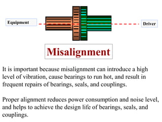
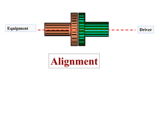
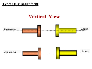
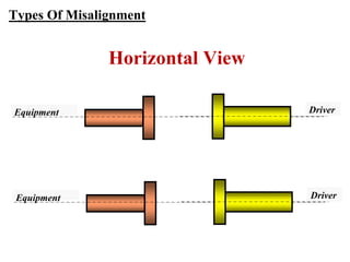
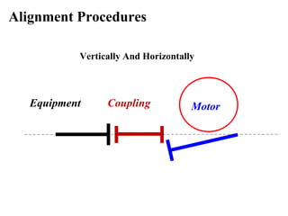
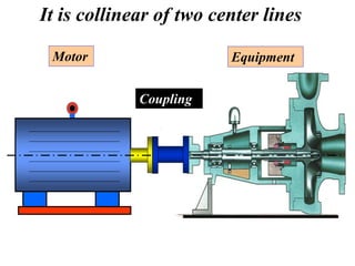
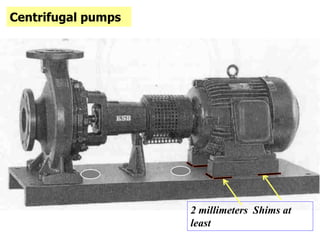
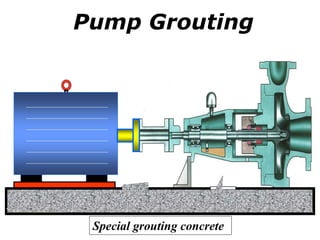
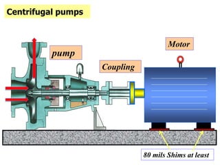
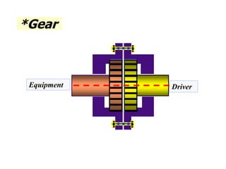
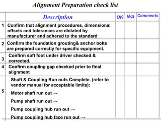
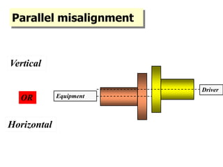
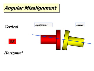
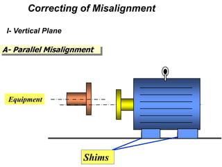
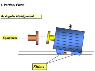
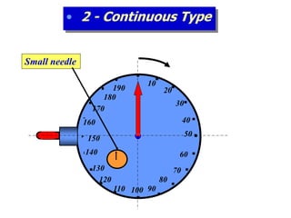
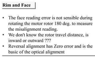
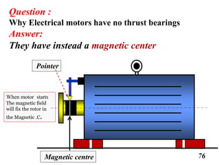
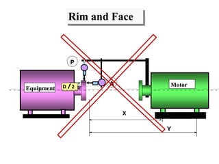
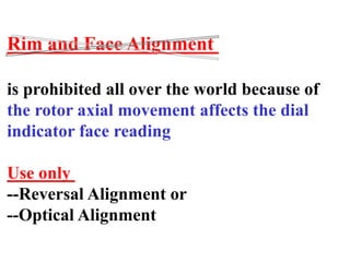
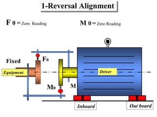
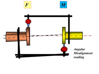
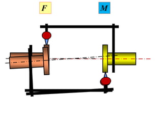
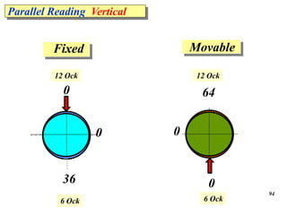
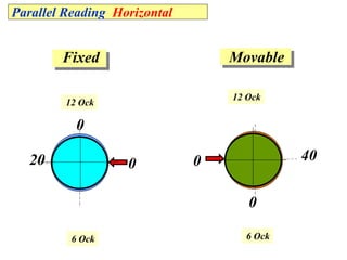
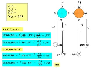
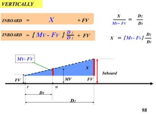
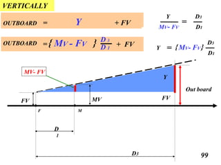
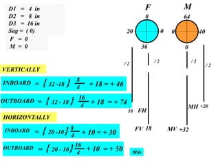
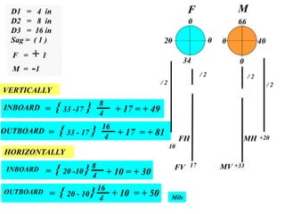
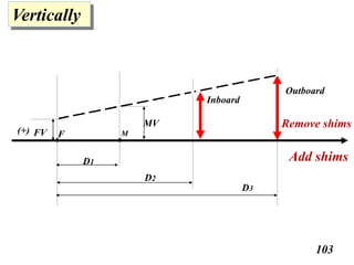
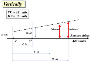
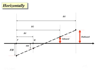
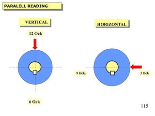
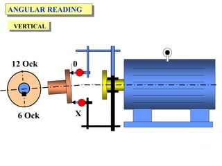
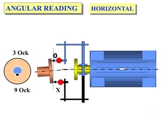
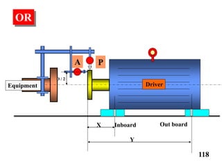
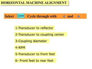
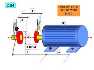
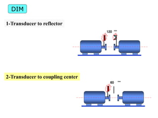
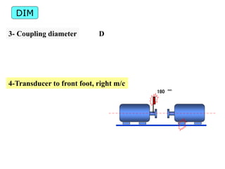
This document provides information on shaft alignment, including definitions of key terms, types of couplings, alignment preparation procedures, how to perform an alignment, and potential consequences of misalignment. Shaft alignment is defined as positioning the rotational centers of two or more shafts to be co-linear under operating conditions. Proper alignment reduces vibration, bearing wear, and power consumption. The document outlines methods for measuring and correcting offset and angular misalignment.
Shaft alignment is the process of aligning two or more shafts to minimize misalignment. There are three main types of misalignment: parallel/lateral, angular, and combined angular and lateral. Misaligned shafts can cause vibration, noise, bearing damage, and shaft or coupling damage. Shaft alignment techniques include conventional methods using dial indicators, laser alignment equipment, and computer-based systems. The alignment procedure involves preliminary checks, sag measurements, and adjusting the position of one shaft relative to the other until indicators show alignment within tolerance.
This document discusses shaft alignment, including definitions, symptoms of misalignment, pre-alignment checks, types of alignment, alignment methods, and effects of misalignment. It defines shaft alignment as positioning rotational centers of two or more shafts to be co-linear under normal operation. Symptoms of misalignment include premature failures, vibration, high temperatures, leakage, and structural issues. Methods discussed include indicator-based rim and face alignment and reverse shaft alignment using graphical techniques. Laser alignment is highlighted as an efficient modern method. Misalignment can cause excessive vibration, noise, lost production, poor quality, and reduced profits.
This document provides information on machinery alignment including definitions, types of misalignment, symptoms, causes, methods, and tools. It defines alignment as positioning rotating shafts so their centerlines match under operating conditions. The two main types of misalignment are radial, where shafts are parallel but offset, and axial, where one shaft is angled relative to the other. Methods discussed include rough alignment using straight edges or wires, and precision alignment using rim and face, reverse/graphical, or laser techniques. Tolerances, symptoms like vibration, and effects like increased wear are also covered.
This document discusses shaft couplings and alignment. It describes different types of shaft couplings like flange, sleeve, muff couplings. It discusses the requirements of good shaft couplings and problems that can occur in couplings. The document also covers alignment of shafts, methods to detect and correct misalignment like soft foot. It describes different alignment methods including dial gauge, reverse indicator and laser alignment. It discusses the effects of misalignment on vibration and characteristics to identify different types of misalignments.
This document discusses rotating equipment alignment. It provides information on:
1. Types of couplings used in shaft alignment like rigid, flexible, gear, and torque converters.
2. The importance of proper shaft alignment to reduce vibration, heat, and maximize equipment life. Misalignment can cause early bearing failure.
3. Alignment procedures including preparation checks, use of dial indicators, and correction of parallel and angular misalignments.
4. Factors that affect alignment like thermal growth, soft foot, pipe strain, and runout must be considered.
Pre-alignment is important to save time and money during shaft alignment. It involves observing the system for any issues like soft foot, thermal growth potential, or worn components. The alignment target or tolerance should be determined based on factors like coupling type and speed. Soft foot must be corrected by shimming feet to be level before alignment. Shaft alignment is done in four steps - correcting angular misalignment vertically, then parallel offset vertically, then angular misalignment horizontally, then parallel offset horizontally. Backlash and vibration need to be controlled during measurement.
This document discusses the primary causes of premature rotating machinery failures due to misalignment. It finds that 50-70% of such failures are misalignment-related. While alignment methods and tools have improved, misalignment still frequently occurs due to a lack of understanding machine concepts, misconceptions about coupling flexibility, and failure to address all potential sources of misalignment beyond just achieving tolerance specifications. These sources include issues like pipe strain, thermal growth, bent shafts, soft foot, poor foundations, and excessive coupling runout. Addressing misalignment requires analyzing its various potential root causes.
This document provides instructions for properly aligning coupled machinery. It outlines important checks to perform before starting alignment like ensuring low shaft and coupling runout. It describes taking initial alignment readings and calculating required movement if misalignment is found. The key steps are correcting for radial and axial misalignment separately, then total alignment by adding or removing shims at the machine legs as needed. The final step confirms alignment is within tolerance by taking a last reading. Overall the document stresses performing top-bottom alignment before side-to-side for best results.
Shaft alignment is the positioning of two or more rotating shafts so their center lines form a single line when machines are working normally. There are three types of misalignments: parallel offset, angular offset, and combination offset. Common methods for shaft alignment include straightedge alignment, multiple dial gauge alignment, and laser alignment. Properly aligning shafts reduces friction, wear, energy consumption, vibration, and the risks of premature equipment breakdown. Shaft alignment increases machine reliability and saves costs for industries.
This document provides an overview of machine alignment, including definitions of different types of misalignment, causes of misalignment, effects of misalignment, and methods for detecting and correcting misalignment. It discusses alignment techniques such as using straight edges, dial indicators, and lasers. Precise alignment requires preparing machines by checking for issues like soft foot, pipe strain, coupling gaps, and runout before implementing alignment methods.
The document discusses soft foot diagnosis and correction using laser alignment tools. It describes different types of soft foot issues like rocking, angled, and induced soft foot. Rocking soft foot has higher values at diagonally opposed corners. The document shows an example of diagnosing and correcting a rocking soft foot issue using laser measurement values and suggested shim corrections. It emphasizes that the type of soft foot must be correctly identified to determine the proper correction method. Laser tools can accurately detect and diagnose soft foot issues to expedite the correction process.
Shaft alignment is the process of positioning two or more rotating shafts so their centerlines are aligned when machines are operating normally. Misalignment can cause damage like abnormal bearing wear. There are several methods to check alignment including using a piano wire or line-of-sight with a telescope. For a piano wire method, the wire is tensioned and distances from it to bearings are measured. For a telescopic method, targets are mounted on stationary points and the telescope is used to align the rotating components by sighting through the targets. Proper shaft alignment is important for reducing vibrations and extending component life.
Mechanical seals provide a running seal between rotating and stationary parts in pumps. They have advantages over conventional packing such as reduced leakage to meet environmental standards, lower maintenance costs, and ability to seal higher pressures. The basic components of a mechanical seal are the primary seal faces (one stationary, one rotating), secondary seals, and hardware. Seals work by creating a tight sealing contact between flat faces, and can be classified by type (pusher, unbalanced, etc.) and arrangement (single, double, cartridge). Proper seal selection requires considering the liquid, pressure, temperature, liquid characteristics, and reliability/emission needs.
This document discusses bearings and lubrication. It defines bearings as any support in direct contact with a moving machine part that is designed to minimize friction. The main types of bearings are described as anti-friction bearings, which provide rolling contact, and plain bearings, which have sliding contact. Anti-friction bearings like ball and roller bearings are advantageous because they have lower starting friction than plain bearings. Plain bearings can use materials like bronze and are simpler but have higher wear. Proper lubrication is also discussed, including different lubrication systems like oil misting which has advantages like lower temperatures and positive pressure prevention of contamination.
Bearing failure and its Causes and Countermeasuresdutt4190
A brief review about bearing and failure of its various parts due to other possibilities than design such as manufacturing, improper service and handling and other similar aspects.
Misalignment is probably the most common cause of machinery malfunction. A poorly aligned machine can cost a factory 20% to 30% in machine down time, replacement parts, inventory, and energy consumption. The payback from aligning machinery to extend the operating life and optimize process conditions is very large. At first glance it seems that aligning two mating shafts should be a simple process. In the real world, however, there are many complicating factors. For example, either one or both shafts may be locked or have limited rotation. One or both shafts may float axially. The machine may have a soft or sprung foot at one or more locations along with a soft and/or warped baseplate. The alignment positions may become bolt bound. Keeping in mind that acceptable final alignment is typically less than 2 mils, maintenance professionals often find it very challenging to attain proper alignments.
The Ultimate Tool for Teaching Shaft Alignment
SpectraQuest’s Shaft Alignment Trainer (SAT) is the most comprehensive device on the market for shaft alignment training. It is designed for studying a wide variety of problems that can arise when two shafts are misaligned. It is a hands-on trainer for maintenance professionals. It provides a unique mechanism for studying soft and sprung foot. It is a realistic simulator with a one inch diameter shaft that fits standard couplings. Its modular design facilitates simulation of multiple element drive trains. The SAT is available in a two train and in a three train configuration. Each SAT incorporates two fully adjustable modular units featuring horizontal jack bolts, calibrated and reference dials, and replaceable feet. The three train SAT adds a fixed module which simulates a non-adjustable machine, but, the shaft can be offset and axially floated.
Shaft alignment is the process of positioning two or more rotating shafts so their centerlines are aligned when machines are operating normally. Misalignment can cause damage like abnormal bearing wear. There are several methods to check alignment including using a piano wire or line-of-sight with a telescope. For a piano wire method, the wire is tensioned and distances from it to bearings are measured. For a telescopic method, targets are mounted on stationary points and the telescope is used to align the rotating components by sighting through the targets. Proper shaft alignment is important for reducing vibrations and extending component life.
In this PPT you will learn about Bearings, Its Types, Classifications, Uses, How to select them according to use with proper and neat Diagrams and pictures.
Bearing Description about basic, types, failure causesPankaj
This document discusses different types of bearings. It begins by defining a bearing as a device that allows constrained relative motion between two parts, typically rotation or linear movement. It then classifies bearings based on the motions they allow and their principle of operation. The document goes on to describe various types of bearings in detail, including ball bearings, roller bearings, thrust bearings, tapered roller bearings, and cylindrical roller bearings. It provides information on the characteristics, advantages, applications, and physical features of each bearing type.
This document provides information on alignment of machines. It defines alignment as positioning machines so their rotating shafts are collinear when at operating temperature. Misalignment can be caused by thermal expansion, vibrations, forces from pipes/supports or soft foot. Effects include increased vibration, bearing damage, friction and power consumption. There are three types of misalignment: offset, angular, and skew (offset and angular combined). Alignment is measured using vibration analysis, phase analysis and wear particle analysis. Methods to correct misalignment include rough alignment using straight edges or wires and precision alignment using face and rim or reverse indicator methods. Laser alignment provides an accurate alternative.
Unit 5- balancing of reciprocating masses, Dynamics of machines of VTU Syllabus prepared by Hareesha N Gowda, Asst. Prof, Dayananda Sagar College of Engg, Blore. Please write to hareeshang@gmail.com for suggestions and criticisms.
This document discusses machine balancing and provides definitions and explanations of key terms. It describes the different types of unbalance including static, couple, and dynamic unbalance. It explains the causes of unbalance such as uneven mass distribution, wear, corrosion, and assembly issues. The document also outlines the methods used for static and dynamic balancing of rigid and flexible rotors. It provides standards and formulas for determining acceptable balance tolerances.
John Crane gas seals provide maximum reliability through ensuring a clean and dry seal environment. Key factors include filtering the gas to 1 micron, using coalescing filters to remove liquids, heating the gas above hydrate and liquid formation points, and using an SEPro system to provide heated filtered gas to the seals during shutdown periods. It is also important to properly monitor the outer barrier seal, ensure adequate separation from bearing oil, and have the OEM test the job seal system to validate performance matches duty conditions.
Bearings are used in machines to allow rotating parts to move freely while supporting loads. There are two main types of bearings: sliding contact/frictional bearings which operate on sliding friction; and rolling contact/anti-frictional bearings which have rolling elements like balls or rollers to reduce friction. Rolling contact bearings can carry heavier loads than sliding contact bearings and have lower friction, but are more complex and expensive to manufacture. Bearings are classified based on the type of load they support, such as radial loads, axial/thrust loads, or combined loads. Common bearing types include ball bearings, roller bearings, tapered roller bearings, and needle roller bearings.
This document discusses vibration analysis at thermal power plants. It outlines the objectives of vibration monitoring, which include improving equipment protection, safety, maintenance procedures, and extending equipment life. Vibration monitoring measures characteristics like amplitude and frequency to identify abnormal conditions. Common defects that can be detected through vibration analysis are unbalance, misalignment, loose components, rotor rub, bearing issues, and blade/vane pass frequencies. Online monitoring systems are used at thermal plants to continuously monitor critical equipment like turbines, generators, and pumps to detect faults early and avoid failures. Standards provide guidelines for effective vibration analysis and maintenance.
The document discusses errors in machine tool positioning accuracy caused by mechanical influences like thermal expansion of ball screws used for position measurement. Using a rotary encoder and ball screw for position feedback includes errors from pitch variation and deformation as temperatures rise. Tests show significant drift over time and deviations from ideal paths at high speeds. These issues are largely avoided by using a linear encoder for closed-loop control of the entire feed drive system.
This document discusses factors that influence gear reliability and methods for measuring gear accuracy. It describes three quality classifications for gears from commercial to ultraprecision and standards for gear tolerances. Methods for measuring individual geometric features like profile and lead as well as functional measurements using composite errors are presented. Tolerances, variations, and required inspection information are also covered.
This document discusses shaft alignment and the benefits of precision alignment. It defines shaft alignment as reducing misalignment between two connected shafts so their centers of rotation are collinear during operation. Good alignment reduces vibration and wear, lowering costs. Methods like dial indicators and laser alignment are described. Laser alignment is generally more accurate as it eliminates errors from sag or runout. The document also discusses measuring thermal growth between offline and running conditions using OL2R fixtures to precisely align shafts accounting for expansion.
This document provides an overview of machinery alignment. It defines alignment as arranging the centerlines of rotating shafts in a straight line when machines are at operating temperature. Misalignment occurs when shaft centerlines do not match up and can be radial or angular. The document discusses types of misalignment, methods of alignment including straight edge, rim and face, and laser, symptoms of misalignment, tools used, and importance of precision alignment. It provides guidance on pre-alignment checks like foundation, piping, shims, and indicates alignment tolerances are required for proper machinery function.
Computer based Wireless Automobile Wheel Alignment system using Accelerometertheijes
A computer based wireless automobile wheel alignment measurement system using accelerometer is presented in this paper, which has the advantages of simple circuit, low cost , high resolution with high working reliability. The causes and effects of improper wheel alignment by traditional methods are analyzed in the model. In this system wireless transmission techniques are adopted to transmit data between measuring unit and computer. This makes the measurement operation much easier. This paper presents unique and innovative use of accelerometer for the measurement of automobile wheel parameters, such as camber and toe. The hardware and software realizations are also explored in this paper. The system practical applications shows that its performance meets the design requirements.
IRJET- Analysis of Stress and Bending Strength of Involutes Spur Gears with F...IRJET Journal
This document analyzes and compares the bending stress and strength of asymmetric and symmetric spur gear profiles through finite element analysis. It develops a computer program to estimate the variation of maximum bending stress and contact ratio based on tooth number and drive side pressure angle for asymmetric gears. The FEM analysis shows that asymmetric teeth have lower bending stress than symmetric teeth. It also confirms that increasing the drive side pressure angle decreases bending stress and increases load capacity. While the maximum bending stress value changes with the gear profile, the location of maximum bending stress remains the same in FEM analysis for both asymmetric and symmetric gears. The document concludes that optimizing the fillet profile of asymmetric gears can further reduce bending stress levels.
This document discusses a proposed computer-based wireless wheel alignment system using an accelerometer. It begins with an introduction to wheel alignment and its importance in vehicle maintenance. It then describes the key parameters that determine wheel alignment: caster, camber, toe, thrust, and ride height. The document outlines the design of the proposed system, which uses an ADXL335B accelerometer and Arduino microcontroller to measure alignment angles wirelessly. It concludes that the system could offer advantages over traditional methods like low cost, reliability, and precision, while allowing for faster alignment checks.
This document provides information on bevel gears, including their design, applications, advantages, and disadvantages. It discusses straight and spiral bevel gear types and proportions. Formulas are presented for calculating forces, bending stresses, contact stresses, and permissible stress values for bevel gear design. Diagrams illustrate bevel gear geometry, terminology, and force analysis. The document is intended to inform the design of bevel gear elements and machine components.
This document provides an overview of shaft alignment techniques. It begins by defining shaft alignment and describing its importance for preventing machine breakdown. It then discusses various methods for measuring alignment, including using dial indicators, lasers, and visual inspection. Guidelines are provided for how precisely machines should be aligned based on factors like speed and coupling type. Common causes of misalignment and potential symptoms are also reviewed.
This document provides the design details for a 4-speed manual transmission. It includes the preliminary need, specifications, and constraints provided by the boss. The overall design is shown with the input shaft, output shaft, and 4-gear countershaft assembly. Key dimensions like gear tooth counts, pitch, centerline distance, and face widths are specified. Load calculations were performed to analyze theoretical critical locations and ensure the design meets the torque requirements.
presentation on CENTRE DISTANCE VARIATION,MINIMUM NUMBER OF TEETH,CONTACT RAT...STAVAN MACWAN
This document discusses various topics related to gears, including:
1. Center distance variation in gears can affect time-varying mesh stiffness and gear vibration. A new kinematic model is proposed to evaluate actual contact positions under varying center distances.
2. The minimum number of teeth for gears without undercutting is typically 17, though gears with fewer can be used if strength and contact ratio allow.
3. Contact ratio measures the average number of teeth in contact during engagement, and is typically 1.3-1.4 for machine tool components depending on the application's precision requirements.
4. Spur gears have straight, parallel teeth but produce high stresses and noise. Helical gears generate thrust but allow
IRJET- Finite Element Analysis Comparison of Spur Gears between Standard ...IRJET Journal
This document compares the finite element analysis of standard involute spur gears and modified involute spur gears. It describes the design and modeling of both gear profiles in CAD software. A finite element analysis is then conducted on both gear models to analyze deformation, equivalent elastic strain, and von-mises stress. The results show that the modified gear profile has slightly higher deformation but around the same equivalent strain and stress as the standard gear profile. The document concludes that tooth profile modifications can help reduce noise and vibrations while increasing gear strength with little effect on stress and deformation.
IRJET- Quality Analysis of Connecting Rod for Axial Misalignment: Bend Ge...IRJET Journal
This document analyzes the causes of axial misalignment, or bending, in connecting rods during machining operations. Regression analysis identified four factors that significantly impact bend generation: big end bottom side ovality, big end x-side taper, small end bottom side ovality, and width. Further factorial analysis showed that big end bottom side ovality is the primary cause of bend. A fault tree analysis was conducted to determine the root causes of ovality, including issues with locating fixtures, clamping, machining parameters, spindle balancing, and semi-finished rod quality. Addressing these root causes can help reduce ovality and bending in connecting rods.
Derek Oung 2015 NFR Wheel Center Design DocumentationDerek Oung
This document outlines the goals, design constraints, and analysis for the wheel centers of a Formula SAE race car. The wheel centers must withstand loads from acceleration, braking, and cornering while allowing clearance and minimizing stress, deformation, buckling, and rotational inertia. The design is constrained by the hub, rim, and number of bolts. Materials and a safety factor are selected to withstand the estimated load cycles. Analyses determine the number and placement of pins and bolts.
Gears come in many types that are classified based on the orientation of their axes. Common gear types include spur gears, helical gears, bevel gears, worm gears, and screw gears. Gears transmit motion and power between parallel, intersecting, or nonparallel/nonintersecting shafts. Their efficiency depends on the type, ranging from 98-99.5% for spur gears to 30-90% for worm gears. Terminology includes terms to describe linear and circular dimensions, angles, and other characteristics of gears.
Sanjiv Kumar "Vibration Signature Analysis of 4 Jaw Flexible Coupling Considering Misalignment in Two Planes.", International Research Journal of Engineering and Technology (IRJET), Vol2,issue-01 March 2015. e-ISSN:2395-0056, p-ISSN:2395-0072. www.irjet.net
Abstract
Misalignment and unbalancing are the most possible causes of machine vibrations. A misaligned rotor always causes more vibration and generates excessive force in the bearing area and reduces the life of the machine. Coupling misalignment is a condition where the shaft of the driver machine and the driven machine are not on the same centerline. The non-coaxial condition can be parallel misalignment or angular misalignment. The more common condition is a combination of the two in both the horizontal and vertical direction. We are forced into this situation of coupling alignment because equipment from different suppliers must be mated together. Misalignment is temperature dependent. All materials expand with increasing temperature, and metal is no exception. Motors warm up several degrees, and the driven machine may warm up or cool down from ambient depending on the fluid it is handling. Understanding and practicing the fundamentals of rotating shaft parameters is the first step in reducing unnecessary vibration, reducing maintenance costs and increasing machine uptime. By the term two planes in our work, we mean that two rotors are used for the analysis of misaligned vibrations. If only one rotor is used then this system is called a single plane system. In this paper, experimental studies were performed on a 2 rotor dynamic test apparatus to predict the vibration spectrum for rotor misalignment. A 4 Jaw flexible coupling was used in the experiments. The rotor shaft accelerations were measured at rotor speed of 30 Hz i.e. 1800 RPM using accelerometer and a Dual Channel Vibration Analyzer (DCVA) under the aligned (baseline) and misaligned conditions. The experimental frequency spectrum was also obtained for both baseline and misaligned condition under different misaligned forces. The experimental results of aligned and misaligned rotors are compared at two different rotor locations.
IRJET- Sensitivity Analysis Study of CVT Parameters using Mathematical ModelIRJET Journal
This document presents a mathematical model to analyze the sensitivity of continuously variable transmission (CVT) parameters. It discusses the components of a CVT system including V-belts and variable diameter pulleys. The methodology describes developing equations for the primary actuator using centrifugal force on rollers, the V-belt geometry, and the secondary actuator incorporating a helical spring. The results section shows the mathematical model was verified against dynamometer test data and found to be comparable, indicating it can be used to study effects of varying CVT parameters on vehicle performance.
This document describes an active suspension system for a vehicle. It discusses the objectives and methodology of the project. The methodology section covers properties of suspension systems like spring rate, wheel rate, weight transfer, travel and damping. It describes the fundamental components of any suspension system including springs, dampers and anti-sway bars. It provides diagrams of typical suspension parts and the contact patch deformation during cornering and over bumps. The document outlines the chapters on literature review, objectives, active suspension design and functions. In conclusion, it presents the abstract which states that the active suspension system aims to improve ride comfort and handling by reducing sprung mass acceleration and suspension deflection.
Use PyCharm for remote debugging of WSL on a Windo cf5c162d672e4e58b4dde5d797...shadow0702a
This document serves as a comprehensive step-by-step guide on how to effectively use PyCharm for remote debugging of the Windows Subsystem for Linux (WSL) on a local Windows machine. It meticulously outlines several critical steps in the process, starting with the crucial task of enabling permissions, followed by the installation and configuration of WSL.
The guide then proceeds to explain how to set up the SSH service within the WSL environment, an integral part of the process. Alongside this, it also provides detailed instructions on how to modify the inbound rules of the Windows firewall to facilitate the process, ensuring that there are no connectivity issues that could potentially hinder the debugging process.
The document further emphasizes on the importance of checking the connection between the Windows and WSL environments, providing instructions on how to ensure that the connection is optimal and ready for remote debugging.
It also offers an in-depth guide on how to configure the WSL interpreter and files within the PyCharm environment. This is essential for ensuring that the debugging process is set up correctly and that the program can be run effectively within the WSL terminal.
Additionally, the document provides guidance on how to set up breakpoints for debugging, a fundamental aspect of the debugging process which allows the developer to stop the execution of their code at certain points and inspect their program at those stages.
Finally, the document concludes by providing a link to a reference blog. This blog offers additional information and guidance on configuring the remote Python interpreter in PyCharm, providing the reader with a well-rounded understanding of the process.
Generative AI Use cases applications solutions and implementation.pdfmahaffeycheryld
Generative AI solutions encompass a range of capabilities from content creation to complex problem-solving across industries. Implementing generative AI involves identifying specific business needs, developing tailored AI models using techniques like GANs and VAEs, and integrating these models into existing workflows. Data quality and continuous model refinement are crucial for effective implementation. Businesses must also consider ethical implications and ensure transparency in AI decision-making. Generative AI's implementation aims to enhance efficiency, creativity, and innovation by leveraging autonomous generation and sophisticated learning algorithms to meet diverse business challenges.
https://www.leewayhertz.com/generative-ai-use-cases-and-applications/
Software Engineering and Project Management - Introduction, Modeling Concepts...Prakhyath Rai
Introduction, Modeling Concepts and Class Modeling: What is Object orientation? What is OO development? OO Themes; Evidence for usefulness of OO development; OO modeling history. Modeling
as Design technique: Modeling, abstraction, The Three models. Class Modeling: Object and Class Concept, Link and associations concepts, Generalization and Inheritance, A sample class model, Navigation of class models, and UML diagrams
Building the Analysis Models: Requirement Analysis, Analysis Model Approaches, Data modeling Concepts, Object Oriented Analysis, Scenario-Based Modeling, Flow-Oriented Modeling, class Based Modeling, Creating a Behavioral Model.
Optimizing Gradle Builds - Gradle DPE Tour Berlin 2024Sinan KOZAK
Sinan from the Delivery Hero mobile infrastructure engineering team shares a deep dive into performance acceleration with Gradle build cache optimizations. Sinan shares their journey into solving complex build-cache problems that affect Gradle builds. By understanding the challenges and solutions found in our journey, we aim to demonstrate the possibilities for faster builds. The case study reveals how overlapping outputs and cache misconfigurations led to significant increases in build times, especially as the project scaled up with numerous modules using Paparazzi tests. The journey from diagnosing to defeating cache issues offers invaluable lessons on maintaining cache integrity without sacrificing functionality.
Advanced control scheme of doubly fed induction generator for wind turbine us...IJECEIAES
This paper describes a speed control device for generating electrical energy on an electricity network based on the doubly fed induction generator (DFIG) used for wind power conversion systems. At first, a double-fed induction generator model was constructed. A control law is formulated to govern the flow of energy between the stator of a DFIG and the energy network using three types of controllers: proportional integral (PI), sliding mode controller (SMC) and second order sliding mode controller (SOSMC). Their different results in terms of power reference tracking, reaction to unexpected speed fluctuations, sensitivity to perturbations, and resilience against machine parameter alterations are compared. MATLAB/Simulink was used to conduct the simulations for the preceding study. Multiple simulations have shown very satisfying results, and the investigations demonstrate the efficacy and power-enhancing capabilities of the suggested control system.
Build the Next Generation of Apps with the Einstein 1 Platform.
Rejoignez Philippe Ozil pour une session de workshops qui vous guidera à travers les détails de la plateforme Einstein 1, l'importance des données pour la création d'applications d'intelligence artificielle et les différents outils et technologies que Salesforce propose pour vous apporter tous les bénéfices de l'IA.
Electric vehicle and photovoltaic advanced roles in enhancing the financial p...IJECEIAES
Climate change's impact on the planet forced the United Nations and governments to promote green energies and electric transportation. The deployments of photovoltaic (PV) and electric vehicle (EV) systems gained stronger momentum due to their numerous advantages over fossil fuel types. The advantages go beyond sustainability to reach financial support and stability. The work in this paper introduces the hybrid system between PV and EV to support industrial and commercial plants. This paper covers the theoretical framework of the proposed hybrid system including the required equation to complete the cost analysis when PV and EV are present. In addition, the proposed design diagram which sets the priorities and requirements of the system is presented. The proposed approach allows setup to advance their power stability, especially during power outages. The presented information supports researchers and plant owners to complete the necessary analysis while promoting the deployment of clean energy. The result of a case study that represents a dairy milk farmer supports the theoretical works and highlights its advanced benefits to existing plants. The short return on investment of the proposed approach supports the paper's novelty approach for the sustainable electrical system. In addition, the proposed system allows for an isolated power setup without the need for a transmission line which enhances the safety of the electrical network
Software Engineering and Project Management - Software Testing + Agile Method...Prakhyath Rai
Software Testing: A Strategic Approach to Software Testing, Strategic Issues, Test Strategies for Conventional Software, Test Strategies for Object -Oriented Software, Validation Testing, System Testing, The Art of Debugging.
Agile Methodology: Before Agile – Waterfall, Agile Development.
VARIABLE FREQUENCY DRIVE. VFDs are widely used in industrial applications for...PIMR BHOPAL
Variable frequency drive .A Variable Frequency Drive (VFD) is an electronic device used to control the speed and torque of an electric motor by varying the frequency and voltage of its power supply. VFDs are widely used in industrial applications for motor control, providing significant energy savings and precise motor operation.
Redefining brain tumor segmentation: a cutting-edge convolutional neural netw...IJECEIAES
Medical image analysis has witnessed significant advancements with deep learning techniques. In the domain of brain tumor segmentation, the ability to
precisely delineate tumor boundaries from magnetic resonance imaging (MRI)
scans holds profound implications for diagnosis. This study presents an ensemble convolutional neural network (CNN) with transfer learning, integrating
the state-of-the-art Deeplabv3+ architecture with the ResNet18 backbone. The
model is rigorously trained and evaluated, exhibiting remarkable performance
metrics, including an impressive global accuracy of 99.286%, a high-class accuracy of 82.191%, a mean intersection over union (IoU) of 79.900%, a weighted
IoU of 98.620%, and a Boundary F1 (BF) score of 83.303%. Notably, a detailed comparative analysis with existing methods showcases the superiority of
our proposed model. These findings underscore the model’s competence in precise brain tumor localization, underscoring its potential to revolutionize medical
image analysis and enhance healthcare outcomes. This research paves the way
for future exploration and optimization of advanced CNN models in medical
imaging, emphasizing addressing false positives and resource efficiency.
Embedded machine learning-based road conditions and driving behavior monitoringIJECEIAES
Car accident rates have increased in recent years, resulting in losses in human lives, properties, and other financial costs. An embedded machine learning-based system is developed to address this critical issue. The system can monitor road conditions, detect driving patterns, and identify aggressive driving behaviors. The system is based on neural networks trained on a comprehensive dataset of driving events, driving styles, and road conditions. The system effectively detects potential risks and helps mitigate the frequency and impact of accidents. The primary goal is to ensure the safety of drivers and vehicles. Collecting data involved gathering information on three key road events: normal street and normal drive, speed bumps, circular yellow speed bumps, and three aggressive driving actions: sudden start, sudden stop, and sudden entry. The gathered data is processed and analyzed using a machine learning system designed for limited power and memory devices. The developed system resulted in 91.9% accuracy, 93.6% precision, and 92% recall. The achieved inference time on an Arduino Nano 33 BLE Sense with a 32-bit CPU running at 64 MHz is 34 ms and requires 2.6 kB peak RAM and 139.9 kB program flash memory, making it suitable for resource-constrained embedded systems.
DEEP LEARNING FOR SMART GRID INTRUSION DETECTION: A HYBRID CNN-LSTM-BASED MODELijaia
As digital technology becomes more deeply embedded in power systems, protecting the communication
networks of Smart Grids (SG) has emerged as a critical concern. Distributed Network Protocol 3 (DNP3)
represents a multi-tiered application layer protocol extensively utilized in Supervisory Control and Data
Acquisition (SCADA)-based smart grids to facilitate real-time data gathering and control functionalities.
Robust Intrusion Detection Systems (IDS) are necessary for early threat detection and mitigation because
of the interconnection of these networks, which makes them vulnerable to a variety of cyberattacks. To
solve this issue, this paper develops a hybrid Deep Learning (DL) model specifically designed for intrusion
detection in smart grids. The proposed approach is a combination of the Convolutional Neural Network
(CNN) and the Long-Short-Term Memory algorithms (LSTM). We employed a recent intrusion detection
dataset (DNP3), which focuses on unauthorized commands and Denial of Service (DoS) cyberattacks, to
train and test our model. The results of our experiments show that our CNN-LSTM method is much better
at finding smart grid intrusions than other deep learning algorithms used for classification. In addition,
our proposed approach improves accuracy, precision, recall, and F1 score, achieving a high detection
accuracy rate of 99.50%.
DEEP LEARNING FOR SMART GRID INTRUSION DETECTION: A HYBRID CNN-LSTM-BASED MODEL
Alignment 2020 ok
1. Shaft Alignment
Hassan Mohamed A. M. Hassan
Lead Mechanical Engineer
Worley Parsons Engineers Egypt Ltd.
Cairo Egypt 01223190213
Tel.: +2-02-22706178
Email hasmonem@gmail.com
2. Hassan
Couplings Alignment to determine the
accurate misalignment figures)
1- What is shaft alignment
2- Types of Couplings
3- Alignment Preparation check list
4- Preparation on Alignment
5-How to Do Alignment
6- Reversal Alignment calculation Method
7- Reversal Alignment Graphical Method
(complete with software)
8- Case Studies For Alignment Failure
3. Hassan
Reliability from different perspective
• Centrifugal Compressor Fail to start
• Centrifugal Compressor Alarm and shutdown
Actual Workshop Alignment procedure
4. • Types of Couplings
• Alignment Preparation check list
• Preparation on Alignment
• How to Do Alignment
• Isolation Standard
• (Software for Pumps Alignment Calculations)
• Post assessment
Rotating Equipment Alignment (One of the most cause of failure)
5. It is collinear of two center lines
1-Is the proper positioning of the shaft centerlines of
the driver and driven components.
2-Alignment is accomplished either
A- Shimming
B- Moving a machine component.
Its objective is to obtain a common axis of rotation at
operating equilibrium for two coupled shafts or a train
of coupled shafts.
Rotating Equipment Alignment (One of the most cause of failure)
6. Shafts must be aligned as perfectly as possible
to maximize equipment reliability and life,
particularly for high-speed
It is important because misalignment can introduce
1-High level of vibration
2-Cause bearings to run hot
Proper alignment
1-Reduces power consumption and noise level
2-Helps to achieve the design life of bearings,
seals, and couplings.
Why it is important to make shaft alignment?
7. What is shaft alignment?
Shaft alignment is the positioning of the rotational centers of two or more shafts such
that they are co-linear when the machines are under normal operating conditions.
Proper shaft alignment is not dictated by the total indicator reading (TIR) of the
coupling hubs or the shafts, but rather by the proper centers of rotation of the shaft
supporting members (the machine bearings).
There are two components of misalignment—angular and offset.
Offset misalignment, sometimes referred to as parallel misalignment, is the distance
between the shaft centers of rotation measured at the plane of power transmission.
This is typically measured at the coupling center. The units for this measurement are
mils (where 1 mil = 0.001 in.).
Angular misalignment, sometimes referred to as “gap” or “face,” is the difference in
the slope of one shaft, usually the moveable machine, as compared to the slope of
the shaft of the other machine, usually the stationary machine. The units for this
measurement are comparable to the measurement of the slope of a roof (i.e.,
rise/run). In this case the rise is measured in mils and the run (distance along the
shaft) is measured in inches. The units for angular misalignment are mils/1 in.
As stated, there are two separate alignment conditions that require correction. There
are also two planes of potential misalignment—the horizontal plane (side to side) and
the vertical plane (up and down). Each alignment plane has offset and angular
components, so there are actually four alignment parameters to be measured and
corrected. They are horizontal angularity (HA), horizontal offset (HO), vertical
angularity (VA), and vertical offset (VO).
8. Shaft alignment tolerances
Historically, shaft alignment tolerances have been governed by the coupling
manufacturers’ design specifications. The original function of a flexible
coupling was to accommodate the small amounts of shaft misalignment
remaining after the completion of a shaft alignment using a straight edge or
feeler gauges. Some coupling manufacturers have designed their couplings to
withstand the forces resulting from as much as 3 degrees of angular
misalignment and 0.075 in. (75 mils) of offset misalignment, depending on
the manufacturer and style of the coupling.
Another common tolerance from coupling manufacturers is the gap tolerance.
Typically this value is given as an absolute value of coupling face TIR (as an
example, a specification migh read “face TIR not to exceed 0.005 in.”). This
number can be deceiving depending on the swing diameter of the face dial
indicator or the diameter of the coupling being measured. In fairness, it
should be noted that the tolerances offered by coupling manufacturers are to
ensure the life of the coupling with the expectation that the flexible element
will fail rather than a critical machine component.
9. Shaft alignment is the positioning of the rotational centers of two or more shafts such
that they are co-linear when the machines are under normal operating conditions.
Proper shaft alignment is not dictated by the total indicator reading (TIR) of the
coupling hubs or the shafts, but rather by the proper centers of rotation of the shaft
supporting members (the machine bearings).
There are two components of misalignment—angular and offset.
Offset misalignment, sometimes referred to as parallel misalignment, is the distance
between the shaft centers of rotation measured at the plane of power transmission.
This is typically measured at the coupling center. The units for this measurement are
mils (where 1 mil = 0.001 in.).
If this angular tolerance was applied to a 5 in. diam coupling, the angular alignment
result would be 1 mil/1 in. of coupling diameter or 1 mil of rise per 1 in. of distance
axially along the shaft centerline. If the coupling was 10 in. in diameter, the result of
the alignment would be twice as precise (0.5 mil/1 in.). This would lead one to
conclude that an angular alignment tolerance based on mils/1 in. would be something
that could be applied to all shafts regardless of the coupling diameter.
10. Harmonic forces are dangerous
When shafts are misaligned, forces are generated. These forces can produce great
stresses on the rotating and stationary components. While it is probably true that the
coupling will not fail when exposed to the large stresses as a result of this gross
misalignment, the bearings and seals on the machines that are misaligned will most
certainly fail under these conditions. Typically, machine bearings and seals have small
internal clearances and are the recipient of these harmonic forces, not unlike constant
hammering.
Excessive shaft misalignment, say greater than 2 mils for a 3600 rpm machine under
normal operating conditions, can generate large forces that are applied directly to the
machine bearings and cause excessive fatigue and wear of the shaft seals. In extreme
cases of shaft misalignment, the bending stresses applied to the shaft will cause the
shaft to fracture and break.
Bearing life expectancy
The most prevalent bearings used in machinery, ball and roller bearings, all have a
calculated life expectancy, sometimes called the bearing’s L-10 life— a rating of
fatigue life for a specific bearing. Statistical analysis of bearing life relative to forces
applied to the bearings has netted an equation (see “How Bearing Life is Affected by
Misalignment“) describing how a bearing’s life is affected by increased forces due to
misalignment.
11. As the force applied to a given bearing increases, the life expectancy
decreases by the cube of that change. For instance, if the amount of force as
a result of misalignment increases by a factor of 3, the life expectancy of the
machine’s bearings decreases by a factor of 27.
Quite a bit of research in shaft alignment has been conducted over the past
20 years. The results have led to a much different method of evaluating the
quality of a shaft alignment and to increasingly accurate methods of
correcting misaligned conditions. Based on the research and actual industrial
machine evaluations, shaft alignment tolerances are now more commonly
based on shaft rpm rather than shaft diameter or coupling manufacturers’
specifications. There are presently no specific tolerance standards published
by ISO or ANSI, but typical tolerances for alignment are shown in the table
“Typical Tolerances for Alignment.“
12. Another common method of determining shaft alignment tolerances is to
ensure the machine feet are within a specified distance from what is
considered “zero”. This method also can be misleading. If a machine is
considered to be aligned when the foot corrections are less than 2 mils at
both the front feet and back feet, serious misalignment can sometimes be
present. As a general rule, the smaller the machine footprint (distance from
front feet to back feet), the worse the alignment condition based on these
criteria for alignment tolerance.
In Fig. 1, the motor foot distance front to back is 10 inches. The distance
from the front feet to the center of the coupling is 8 inches. If the front foot
of the motor is left 2 mils high and the back feet are left 2 mils low, the shaft
alignment results will be as follows: vertical angularity of 0.4 mil/1 in. open at
the top of the coupling, and a vertical offset of 5.2 mils high at the plane of
power transmission. If this machine operates at 1800 rpm, it would be
outside the acceptable shaft alignment tolerances. Again, this reinforces that
a set of shaft alignment tolerances based on shaft rpm would apply to all
machines regardless of their footprint. MT
13. 1 -Rigid Couplings :
It is a metal to metal contact (%100 collinear)
2 -Flexible Couplings
* Spacer with shims
* Gear
* Grid
* Rubber
* Others
* Torque converter
Types Of Couplings
14. It is important because misalignment can introduce a high
level of vibration, cause bearings to run hot, and result in
frequent repairs of bearings, seals, and couplings.
Proper alignment reduces power consumption and noise level,
and helps to achieve the design life of bearings, seals, and
couplings.
DriverEquipment
Misalignment
32. CommentsN/AOK
Confirm that alignment procedures, dimensional
offsets and tolerances are dictated by
manufacturer and adhered to the standard
11
Confirm the foundation grouting& anchor bolts
are prepared correctly for specific equipment.
2
3
Confirm soft foot under driver checked &
corrected.
Confirm coupling gap checked prior to final
alignment
4
5
Shaft & Coupling Run outs Complete. (refer to
vendor manual for acceptable limits):
Motor shaft run out →
Pump shaft run out →
Pump coupling hub run out →
Pump coupling hub face run out →
Description
Alignment Preparation check list
33. Confirm the vendor thermal growth correctly for
specific equipment (in case of hot fluid pumping)
6
9 Determine Magnetic centre.
Confirm proper tight for the dial indicator holder
and holding rods
10
Determine mechanical centre8
Confirm the dial indicator is rotated from the top
position to the bottom position during the
alignment procedure.
11
Confirm the proper dial indicators position
during the reversal alignment procedure .
12
Determine the thermal growth if it is not
allowable in the vendor document
7
CommentsN/AOKDescription
47. Preparation on Alignment
1. Before placing a machine on its base, make sure that both
the base and the bottom of the machine are clean, rust free,
and do not have any burrs. Use a wire brush or file on these
areas if necessary.
2. Common practice is to position, level, and secure the
driven unit at the required elevation prior to adjusting the
driver to align with it. Set the driven unit's shaft centerline
slightly higher than the driver.
3. Check the motor supports shims (2mm)under legs.
The following preparatory steps should be taken before
attempting to align a machine train:
48. 4. Use only clean shims that have not been "kinked"
or that have burrs.
5. Make sure the shaft does not have run out.
6. Before starting the alignment procedure, check for
"soft-foot" and correct the condition.
7. Always use the correct tightening sequence
procedure on the hold-down nuts.
8. Determine the amount of indicator sag before
starting the alignment procedure.
Preparation on Alignment
49. 9. Position the stem of the dial indicator so that it is
perpendicular to the surface and half travels..
10. Avoid lifting the prime mover more than is
absolutely necessary to add or remove shims.
11. Jacking bolt assemblies should be welded onto
the bases of all large the prime mover. add them
before starting the alignment procedure.
12. Use jacking bolts to adjust for horizontal offset
and angular misalignment and to hold the prime
mover in place while shimming
Preparation on Alignment
50. Measure and correct
* Magnetic centre
*Mechanical centre
* Thermal growth
* Run out
* Soft foot
* Pipe strain
52. * Soft foot One driver leg is not
settled on the base
Maximum 0.002 “
53. • Soft-foot is the condition when all four of a machine's
feet do not support the weight of the machine.
• It is important to determine if this condition is present
prior to performing shaft alignment on a piece of
machinery.
• As an example, consider a chair with one short leg. The
chair will never be stable unless the other three legs are
shortened or the short leg is shimmed.
• In this example, the level floor is the "plane" and the
bottom tips of the legs are the "points" of the plane.
• Three of the four chair tips will always rest on the floor.
Correcting for Soft-foot
54. Consequences
Placing a piece of machinery in service with
uncorrected soft-foot may result in the following:
• Dial-indicator readings taken as part of the alignment
procedure can be different each time the hold-down nuts are
tightened, loosened, and retightened. This can be extremely
frustrating because each attempted correction can cause a
soft-foot condition in another location.
• The nuts securing the feet to the base may loosen, resulting
in either machine looseness and/or misalignment. Either of
these conditions can cause vibration.
55. • If the nuts do not loosen, metal fatigue may occur at the
source of Soft-foot. Cracks can develop in the support
base/frame and, in extreme cases, the soft-foot may actually
break off.
• Initial Soft-foot Correction the following steps should be
taken to check for and correct soft-foot.
• Before setting the machine in place, remove all dirt, rust,
and burrs from the bottom of the machine's feet, the shims to
be used for leveling, and the base at the areas where the
machine's feet will rest.
• Set the machine in place, but do not tighten the hold-
down nuts.
56. • The following procedure describes the final soft-foot
correction:
• Tighten all hold-down nuts on both the stationary machine
and the machine to be shimmed
• Secure a dial indicator holder to the base of the stationary
machine. The stem of the dial indicator should be in a vertical
position above the foot to be checked. A magnetic-base
indicator holder is most suitable for this purpose.
• Set the dial indicator to zero.
• Completely loosen the hold-down nut on the foot to be
checked. Watch the dial indicator closely for foot movement
during the loosening process.
• If the foot rises from the base when the hold-down nut is
loosened, place beneath the foot an amount of shim stock
equal to the amount of deflection shown on the dial indicator.
Final Soft-foot Correction
57. • Retighten the hold-down nut and repeat the entire process
once again to ensure that no movement occurs.
• Move the dial indicator and holder to the next foot to be
checked and repeat the process. Note: The nuts on all of the
other feet must remain securely tightened when a foot is
being checked for a soft-foot condition.
• Repeat the above process on all of the feet.
• Make a three-point check on each foot by placing a feeler
gauge under each of the three exposed sides of the foot.
• Tightening Hold-Down Nuts Once the soft-foot is removed,
Always tighten the nuts as though the final adjustment has
been made, even if the first set of readings has not been
taken
58. The following procedure should be followed:
After eliminating soft-foot, loosen all hold-down nuts.
• Number each machine foot in the sequence in which the
hold-down nuts will be tightened during the alignment
procedure. The numbers (1, 2, 3, and 4) should be
permanently marked on, or near, the feet.
• It is considered a good idea to tighten the nuts in an X
pattern
" Always tighten the nuts in the sequence in which the
positions are numbered (1, 2, 3, and 4).
• Use a torque wrench to tighten all nuts with the same
amount of torque.
59. • Indicator sag is the term used to describe the bending of
the mounting hardware as the dial indicator is rotated
from the top position to the bottom position during the
alignment procedure.
• Bending can cause significant errors in the indicator
readings that are used to determine vertical
misalignment, especially in rim-and-face.
• The degree to which the mounting hardware bends
depends on the length and material strength of the
hardware.
• To ensure that correct readings are obtained with the
alignment apparatus, it is necessary to determine the
amount of indicator sag present in the equipment and to
correct the bottom or 6 o'clock readings before starting
the alignment process.
Indicator Sag
60. • Indicator sag is best determined by mounting the dial
indicator on a piece of straight pipe of the same length as
in the actual application. Zero the dial indicator at the 12
o'clock, or upright, position and then rotate 180 degrees to
the 6 o'clock position.
• The reading obtained, which will be a negative number, is
the measure of the mounting-bracket indicator sag for 180
degrees of rotation and is called the sag factor.
• All bottom or 6 o'clock readings should be corrected by
subtracting the sag factor.
• When two shafts are perfectly aligned, the mounting rod
should be parallel to the axis of rotation of the shafts.
However, the rod bends or sags by an amount usually
measured in mils (thousandths of an inch)
61. Shaft runout is a common measurement especially for condition monitoring.
Capacitive and eddy-current sensors provide useful non-contact measurement
solutions with distinct advantages and disadvantages.
According to ASME/ANSI B5.54-2005 Methods for Performance Evaluation of
Computer Numerically Controlled Machining Centers, “runout” is the total indicator
reading (TIR) of an instrument measuring against a moving surface. This is usually a
rotary motion and is measured for a full rotation. This means the runout value is a
combination of several types of error motions, form errors, and form factors:
Radial Shaft Runout
Radial runout is perpendicular to the axis of rotation.
Radial shaft runout is a measurement of radial displacement of the shaft surface as
the shaft turns. Assuming a round shaft, contributing factors to radial runout include
shaft straightness, drive/shaft alignment, bearing stiffness, and increasing runout as
the bearings wear. Balance is a runout factor that is dependent on the relationships
between speed and bearing stiffness and wear, and overall system stiffness. Radial
shaft runout is generally used to indicate wear in the drive bearings.
Axial shaft runout is a measurement of the axial displacement of the shaft as it
rotates. This measurement is taken at the center of the shaft (on the rotary axis). Off-
center measurements are called “face runout” in which the flatness and squareness of
the surface become contributing factors to the measurement – factors which are not
of interest in most applications. Axial shaft runout is primarily used for condition
monitoring of the thrust bearing.
Shaft Shape
62. By the definition above, non-round shapes always have significant runout. An
oval or hexagonal shaft which is rotating perfectly will still have significant
runout as the indicator responds to radial displacements of the shaft surface
due to the shaft shape.
This Application Note assumes that the shaft being measured is round.
Radial runout is affected by shaft straightness. If the shaft is bent, runout
measurements will be dependent on the location of the measurement along
the length of the shaft and the location and severity of the bend. If a shaft is
fixed at both ends (e.g. between the drive and a gear box) the maximum
runout will tend to be near the center. If the shaft is only fixed at the drive
end (e.g. motors driving fans or propellers) the runout will tend to be worse
at the floating end of the shaft.
An otherwise straight shaft may be mounted such that the center line of the
shaft is not parallel with the axis of rotation. In this case, runout
measurements will depend on where the measurement is taken along the
shaft.
63. Shaft runout is a common measurement especially for condition monitoring.
Capacitive and eddy-current sensors provide useful non-contact measurement
solutions with distinct advantages and disadvantages.
According to ASME/ANSI B5.54-2005 Methods for Performance Evaluation of
Computer Numerically Controlled Machining Centers, “runout” is the total
indicator reading (TIR) of an instrument measuring against a moving surface.
This is usually a rotary motion and is measured for a full rotation. This means
the runout value is a combination of several types of error motions, form
errors, and form factors:
Radial Shaft Runout
68. Growth factors (Expansion factor) (mil/in./F)
for common materials are as follows:
• For vertical growth, L is usually taken as the vertical
height from the bottom of the foot where shims
touch the machine to the shaft centerline.
• In the case where the machine is mounted on a base
that has significant temperature variations along its
length, L is the vertical distance from the concrete or
other constant temperature base line to the shaft
centerline.
Aluminum 0.0126
Bronze 0.0100
Cast iron, gray 0.0059
Stainless steel 0.0074
Mild steel, ductile iron 0.0063
69. * Thermal growth for hot liquid pumps
X = Shaft Thermal growth
Driver
1- Apply the alignment procedure for the pump at ambient Temp.
2- Heat up the pump by opening the start up bypass for ½ hrs.
3- Put the dial indicator on the shaft and adjust to zero reading
4- close the bypass
5- Take the dial indicator reading after 24 hrs.
6- This reading is the shaft thermal growth thermal growth
7- Add the center line thermal growth reading under the driver legs
Equipment
70. Equipment
1- Apply the alignment procedure for the compressor at ambient Temp.
2- Go to catalogue and read the center line thermal growth amount.
3- Add the center line thermal growth reading under the driver legs
4- If the equipment manual gives the whole equipment thermal growth
The center line thermal growth = whole equipment thermal growth /2
(Ask the vendor to confirm type of catalogue thermal growth )
* Thermal growth for Compressors
X = The center line Thermal growth
Driver
After minutes
of Starting
71. 71
Equipment
This design is to avoid
any thermal growth
As thermal expansion
will be in all directions
Cooling
water
75. Rim and Face
• The face reading error is not sensible during
rotating the motor rotor 180 deg. to measure
the misalignment reading.
• We don't know the rotor travel distance, is
inward or outward ???
• Reversal alignment has Zero error and is the
basic of the optical alignment
76. Driver
76Magnetic centre
When motor starts
The magnetic field
will fix the rotor in
the Magnetic .C.
Question :
Why Electrical motors have no thrust bearings
Answer:
They have instead a magnetic center
Pointer
78. Rim and Face Alignment
is prohibited all over the world because of
the rotor axial movement affects the dial
indicator face reading
Use only
--Reversal Alignment or
--Optical Alignment
79. SAG
The attachment that will be used
Bar Sag on 12 O'clock Position
Measurement of bar sag.
Steel block
Dial indicator
Piece of Pipe
111. Rim and Face
The face reading error is not sensible during
rotating the motor rotor 180 deg. to measure the
misalignment reading.
We don't know the rotor travel distance, is
inward or outward ???
Reversal alignment has Zero error and is the
basic of the optical alignment
112. Driver
112Magnetic centre
When motor starts
The magnetic field
will fix the rotor in
the Magnetic .C.
Question :
Why Electrical motors have no thrust bearings
Answer:
They have instead a magnetic center
Pointer
113. Rim and Face Alignment
is prohibited all over the world because of
the rotor axial movement affects the dial
indicator face reading
Use only
--Reversal Alignment or
--Optical Alignment
120. 120
X =
Y =
D =
Sag = - 1
-16AV
P
0
0 0
0.
A
-14
-16
+8
-6
SAG
= +1
-2
-3
/ 2
PV
AH+8-7PH
/ 2
VERTICALLY
INBOARD
X
D
AV – PV Mils=
HORIZONTALLY
INBOARD
X
D
AH – PH Mils=
OUTBOARD =
Y
D
AH – PH Mils
OUTBOARD =
D
AV – PV Mils
Y
121. X = 4 in
Y = 12 in
D = 4 in
Sag = -1
121
-16AV
P
0
0 0
0
A
-14
-16
+8
-6
SAG
= +1
-2
-3
/ 2
PV
AH+8-7PH
/ 2
12
4
OUTBOARD = { -16} – (-2) = -46
HORIZONTALLY
INBOARD { 4
4
8 } – (-7 ) = +15=
INBOARD { 4
4
-16} – (-2) = -14=
VERTICALLY
12
4
OUTBOARD = { 8 } – (-7) = + 31 Mils
122. AV = -16
D = 4
Y = 12
EXAMPLE
PV = - 2
Inboard
Outboard
PV = - 2
X = 4
PV
AV = - 16 mils
PV = - 2 mils
131. REFLECTOR
Rotate the side thumb
Wheel to raise or lower
the reflector
This lever to lock
The reflector position
1- PRESS and remove transducer cap.
-The laser beam now is on.
-Leave the reflector cap on for now.
-Beam strikes the cap, it should be visible.
- Hold a sheet of paper to locate the beam
M
133. OFF Beam misses detector
Red Blinks quickly
Green Is OFF
END Beam hits non linearized
area of detector
Red & Green Blinks quickly
Alternatively
COORDINATES Beam hits area
of detector
Red & Green Blinks Slowly
Together
OFF
END
-2 1
134. 1- PREPARING FOR ALIGNMENT PROCEDURE
a- Solid flat foundation
b- Machine mobility ( 2 mm higher & screw type positioning )
c- Soft foot ( Must be checked immediately)
d- Thermal growth
135. HORIZONTAL MACHINE ALIGNMENT
Select Cycle through with andDIM
1-Transducer to reflector
2-Transducer to coupling center
3-Coupling diameter
4-RPM
5-Transducer to front feet
6- Front feet to rear feet
141. Rotate the side thumb
Wheel to raise or lower
the reflector
This lever to lock
The reflector position
1- PRESS and remove transducer cap.
-The laser beam now is on.
-Leave the reflector cap on for now.
-Beam strikes the cap, it should be visible.
- Hold a sheet of paper to locate the beam
M
5-Laser beam adjustingM
142. Planned Downtime = Hours used for all planned jobs
(TPM)
Breakdown Time = Hours used for all unplanned jobs
(TBD)
Standby Time = Hours used for standby time
(TSB)
Equipment Key Performance Indicator KPI
Availability Reliability Utilization
Total Period Hours = (TX)
142
145. EXAMPLE
Maintenance Stops For A Compressor Was As Follows:
Total Period Of 3 Months
PM = 216 HRS
BD = 216 HRS
SB = 532 HRS CALCULATE AV , Re , Ut
= 0.8Reliability =
216
2160(Re)
= 80
0
0
0.9 -
Utilization =
(U t)
0.8 -
532
2160
= 0.6 = 60
0
0
= 0.9Availability =
216
2160(Av)
= 90
0
01 -
Solution
145
146. Hassan Hassan
Isolation Standards
What types of process isolation do we have?
Single Block
Double Block and Bleed
Rated Spade or Spectacle Blind
Disconnection or Line Removal
PositiveIsolations
147. Hassan Hassan
Which valves can be used?
Not all valves can be used for isolations.
Butterfly valves, Check valves and Control Valves
cannot be considered to be part of an isolation.
148. Hassan Hassan
Which valves can be used?
Not all valves can be used for isolations.
Butterfly valves, Check valves and Control Valves
cannot be considered to be part of an isolation.
149. Hassan Hassan
Which valves can be used?
Not all valves can be used for isolations.
Butterfly valves, Check valves and Control Valves
cannot be considered to be part of an isolation.
150. Hassan Hassan
Single Valve Isolations
For Minor Work on ANSI 600 and below
Note: ANSI 600 has a Maximum Working
Pressure of 99.3 Bar
Pump
151. Hassan Hassan
Double Block and Bleed
Isolations
For Minor Work on ANSI 900 and above
Note: ANSI 900 has a Maximum Working
Pressure of 149 Bar
Pump
152. Hassan Hassan
Rated Spade or Spectacle Blind
Suitable for all isolations
Usually needs valve isolation first to allow
spade or spec blind isolation
Pump
154. Hassan Hassan
150#
1 Bar
600#
80 Bar
1 Bar
Pump Isolations
Suction may be different pressure rating than
dischargePossibility to over-pressurise suction
Sequence of isolation very important
The Correct Way Normal
Condition,
Pump Shut
Down and
Electrically
Isolated
1) Close the
Discharge Valve
2) Open the
pump vent or
drain.
3) Listen for
signs of passing
valves.
1.Close Discharge
Valve.
2. Close Suction
valve making sure
that Pump
pressure does not
rise.
3. Slowly open
drain valve and
observe pump
pressure fall to
zero.
0 Bar
155. Hassan Hassan
Pump Isolations - What can happen
Suction can be pressurised from discharge
Suction line can be damaged and personnel
can be injured
150#
1 Bar
600#
80 Bar
1 Bar
The Wrong Way
If the suction valve
is closed first, look
what happens:
1) NRVs usually
pass.
2) The Pressure
Builds up at the
pump suction.
10 Bar20 Bar30 Bar
157. Hassan Hassan
Example: LP Water
Pump What type of
isolation is
possible?
Is it good
enough?
How would
you do it?
NRV
NRV
BUTTERFLY
CONTROL
VALVE
BUTTERFLY