More Related Content

PPT

PPT
Mechanical Alignment of equipments in Industries 
PPTX

PPT

PDF
Pumps_alignment_1684283213.pdf 
PPTX
MACHINE ALIGNMENT.pptx. An Useful Presentation to understand Alignment Requir... 
PPTX

PPT
PRESENTATION-SHAFT ALIGNMENT.ppt for industries Similar to All about rotary equipment alignment problem

PDF

PPTX
FCG course alignment MACHINE COUPLING ALIGNMENT.pptx 
PPTX
Rotating Equipment Alignment Method.pptx 
PDF
Effects_of_Misalignment.pdf 
PPTX

PDF
Ludeca a practical-guide-to-shaft-alignment 
PPSX

PDF
An engineers guide 2012 making maintenance matter, pruftechnik 
PDF
compressor alignment procedure -1.pdf 
PPTX
Transcat and Fluke Present: Precision Shaft Alignment Made Easy 
PDF
Lecture01 maintenance installations in machinery 
PPT
Final alignment of rotary equipment like pump.ppt 
PPTX
1 Benefits of alignment FL presentation.pptx 
PPTX

PDF

PPT

PDF

PPT

PPTX

PDF
Laser shaft alignment system LASERALIGNBLUE - english Recently uploaded

PDF
lecture notes digital_design_examples.pdf 
PDF
Alternator Protection.pdf`djdjdjkdkdkdkdkd 
PDF
Finite Automata With Output - Moore and Mealy Machines definitions and Solved... 
PPTX
Unit II Introduction to C programming ppts 
PPTX
Why Hydraulic Flushing Should Never Be Skipped Before Commissioning 
PDF
Robert Walker Epps - A Football Coach 
PPTX
Training Notes_ SBPDCL Apprenticeship Program.pptx 
PPTX
low power design COURSE PREREQUISITES Digital System Design, VLSI Design & El... 
PDF
ENVIRONMENTAL ENGINEERING LABORATORY MANUAL UG Lab Manual - Dept of ESE.pdf 
PDF
Basics of Electronics Simplified by Akash.pdf.pdf.pdf 
PPTX
Amperes Circuital Law and its appliocations 
PPTX
CFP_Unit 3 Decision Control and Looping Statements 
PDF
Engineering Mindset for Everyday Leadership — James Afful [Emerging Leaders o... 
PPTX
Basics_of_Electronics_Simplebysreeragsr.pptx 
PDF
Environmental Engineering (3-0-2) Laboratory.pdf 
PDF
How to Write Research Papers NCBP D3.pdf 
PPT
5.1 Basic concept and hierarchy.ppt1234564 
PPTX
GDG I²IT Freshers' Tech Kickoff Event, Pune 
PPTX
PEMET 413-COMPOSITE MATERIALS-2024 SCHEME-MOD1 LECTURE 5.pptx 
PPTX
Mathematics in Disaster Management school project All about rotary equipment alignment problem
- 1.
1
71535 B ©Copyright SPM Instrument AB 1997
Training Program
On
Machine Alignment
- 2.
2
71535 B ©Copyright SPM Instrument AB 1997
What is Alignment?
It is the correction of relative position of two
machines so that Center lines of two rotating shafts
form a straight line when the machines are working
at normal operating temperature.
- 3.
3
71535 B ©Copyright SPM Instrument AB 1997
Causes Of Misalignment
Thermal expansion - Most machines align cold.
Machine vibrations.
Forces transmitted to the machine by pipe or
support structure.
Soft foot.
Direct coupled machines are not properly aligned.
Poor workmanship.
- 4.
4
71535 B ©Copyright SPM Instrument AB 1997
Effects Of Misalignment
More than 50% problems are due to misalignment.
Causes vibration on the machine
Vibration destroys critical parts of machines like bearings, gears,
seals, coupling etc.
Breaks lubricant film inside the bearing and increase friction.
Increases load on the bearing.
Increase 2 - 17% power consumption.
Generates heat inside the coupling.
- 5.
5
71535 B ©Copyright SPM Instrument AB 1997
Types Of Misalignment
1. Off set
2. Angular
3. Skew - Combination of offset & angular
- 6.
6
71535 B ©Copyright SPM Instrument AB 1997
Offset Misalignment
Increases power
consumption of
the machine.
- 7.
7
71535 B ©Copyright SPM Instrument AB 1997
Effects pin bush
coupling more than
tyre coupling.
Angular Misalignment
- 8.
8
71535 B ©Copyright SPM Instrument AB 1997
Skewed Misalignment
- 9.
9
71535 B ©Copyright SPM Instrument AB 1997
Recognition Of
Misalignment
1. Excessive Radial & Axial vibration
2. Premature / repetitive failure of bearing, seal, coupling.
3. Loose coupling elements.
4. Leakage from the seal.
5. Loose base bolts.
6. Coupling become hot while running.
7. High casing temperature.
- 10.
10
71535 B ©Copyright SPM Instrument AB 1997
Scientific
Diagnosis Of Misalignment
1. Vibration Spectrum Analysis
2. Vibration Phase Analysis
3. Wear Particle Analysis
- 11.
11
71535 B ©Copyright SPM Instrument AB 1997
Angular - Axial vibration at 1X RPM
Offset - Radial vibration at 2X or 3X RPM
Harmonics (3X-10X) generates as severity increases.
•If the 2X amplitude more than 50% of 1X then coupling
damage
starts.
•If the 2X amplitude more than 150% of 1X then machine
should be
stopped for correction.
1. Vibration Spectrum Analysis
- 12.
12
71535 B ©Copyright SPM Instrument AB 1997
Angular - 1800
phase shift in the axial direction across
the coupling.
Offset - 1800
phase shift in the radial direction across
the coupling. 00
to 1800
phase shift occur as the sensor
moves from horizontal to the vertical direction of the
same machine.
Skew - 1800
phase shift in the axial or radial direction
across the coupling.
2. Vibration Phase Analysis
- 13.
13
71535 B ©Copyright SPM Instrument AB 1997
3. Wear Particle Analysis
Curly cutting wear particle of 5:1 to 50:1 aspect
ratio.
- 14.
14
71535 B ©Copyright SPM Instrument AB 1997
Types Of Couplings
Flexible : Pin bush, Tyre, Love joy,
ESBI Valkan tyre
Semi Flexible : Fluid
Rigid : Geared, Resilient
- 15.
15
71535 B ©Copyright SPM Instrument AB 1997
Flexible Coupling
Can flexible coupling take misalignment?
Flexible coupling can be used to take minor
misalignment but it will generate heat and
flexible members will fail prematurely.
- 16.
16
71535 B ©Copyright SPM Instrument AB 1997
Alignment Methods
1. Rough Alignment
(a) Using straight edge
(b) Twin wire method
2. Precision Alignment
(a) Face & Rim
(b) Reverse indicator
- 17.
17
71535 B ©Copyright SPM Instrument AB 1997
Using straight edge
Rough Alignment
- 18.
18
71535 B ©Copyright SPM Instrument AB 1997
Using twin wire
Rough Alignment
- 19.
19
71535 B ©Copyright SPM Instrument AB 1997
Face & Rim Method
- 20.
20
71535 B ©Copyright SPM Instrument AB 1997
Face & Rim Method
Advantages:
1. Good for large dia. coupling hubs where the shafts are close together.
2. To be used where one of the shafts can not rotate during alignment.
3. Easy to use.
Disadvantages:
1. Difficult to take face readings, if there is axial float in
the shaft.
2. Requires removal of coupling spool.
3. More complex alignment calculation.
- 21.
21
71535 B ©Copyright SPM Instrument AB 1997
Reverse Indicator Method
- 22.
22
71535 B ©Copyright SPM Instrument AB 1997
Reverse Indicator Method
Advantages:
1. More accurate than face & rim
method.
2. Readings are not affected by axial
float.
3. Possible to keep the coupling spool.
Disadvantages:
1. Both shafts have to be rotated.
2. Should not be used on close coupled shafts.
3. Difficult to take readings on long shaft.
- 23.
23
71535 B ©Copyright SPM Instrument AB 1997
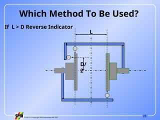
L
D/
2
Which Method To Be Used?
If L > D Reverse Indicator
- 24.
24
71535 B ©Copyright SPM Instrument AB 1997
Calculation can be
made for each of the
method to verify the
readings.
Combination Method
- 25.
25
71535 B ©Copyright SPM Instrument AB 1997
Off Set Angular
RPM mm mm / 100 mm
0000 - 1000 0.13 0.10
1000 - 2000 0.10 0.08
2000 - 3000 0.07 0.07
3000 - 4000 0.05 0.06
4000 - 5000 0.03 0.05
Alignment Tolerance
- 26.
26
71535 B ©Copyright SPM Instrument AB 1997
Disadvantages Of Dial
Indicator Method
More time consuming.
Too much manual work.
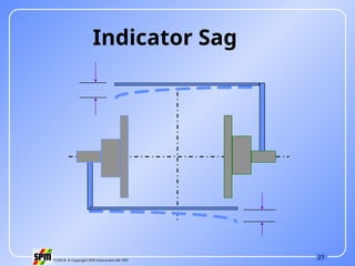
Indicator sag.
Difficult to perform on long shaft.
Difficult to determine soft foot.
Difficult to perform vertical shaft alignment.
- 27.
- 28.
28
71535 B ©Copyright SPM Instrument AB 1997
Angled Foot
Short Foot
Soft Foot
- 29.
29
71535 B ©Copyright SPM Instrument AB 1997
Tightening Of Holding Down Bolts
- 30.
30
71535 B ©Copyright SPM Instrument AB 1997
Perpendicular to
the coupling
surface.
Fixing Of Dial Gauge
- 31.
31
71535 B ©Copyright SPM Instrument AB 1997
Rules For Good Alignment
Clean the machine base. Remove rust burrs
etc.
Use steel or brass shims.
Check indicator sag.
Check soft foot.
Check dial gauges before taking readings.
Use correct bolt tightening procedure.
Don’t lift the machine more than necessary.
Try to put the stem of dial gauge
perpendicular to
the surface of coupling.
Use jack bolts.
- 32.
32
71535 B ©Copyright SPM Instrument AB 1997
Laser Alignment
- 33.
33
71535 B ©Copyright SPM Instrument AB 1997
Light Amplified By Stimulated Emission Of Radiation
Laser was originally emitted by charge sent
through
a gas mixture of Helium & Neon.
Now it emitted by a low power semi conductor
diode
with collimating lenses.
Modulated to avoid interference from other light
source
It is collinear.
Single wave length of 670 nm.
Laser
- 34.
34
71535 B ©Copyright SPM Instrument AB 1997
Laser Alignment
Advantages:
1. Easy to use.
2. Use Reverse Indicator Method.
3. Machine does the calculations.
4. 0 - 20m max. working distance.
5. Selectable high resolution 0.1, 0.01, 0.001mm.
6. No indicator sag.
7. Soft foot measurement program.
8. Horizontal shaft alignment with mim 600
rotation.
9. Vertical shaft alignment program.
10.Thermal or offset compensation.
- 35.
35
71535 B ©Copyright SPM Instrument AB 1997
11. Machine train alignment program.
12. Cardon shaft alignment.
13. Straightness, Flatness, Perpendicularly,
Parallelism measurement.
14. Spindle alignment.
15. Static feet correction.
16. Continuos monitoring.
- 36.
- 37.
- 38.
38
71535 B ©Copyright SPM Instrument AB 1997
Graphical representation
- 39.
39
71535 B ©Copyright SPM Instrument AB 1997
Stationery Machine Movable Machine
+
+
Graphical representation
- 40.
40
71535 B ©Copyright SPM Instrument AB 1997
Graphical representation
Example 1
(Reverse Indicator Method)
SM Dial Reading: -1.50 mm
MM Dial Reading : +0.5 mm
Scale: Y-axis = 10:1
X-axis = 1: 5
- 41.
41
71535 B ©Copyright SPM Instrument AB 1997
+
+
Graphical representation
- 42.
42
71535 B ©Copyright SPM Instrument AB 1997
Graphical representation