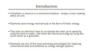
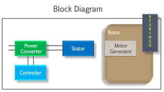
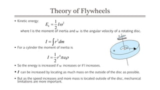
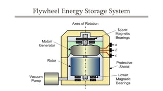
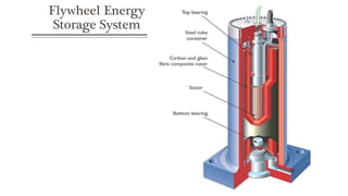
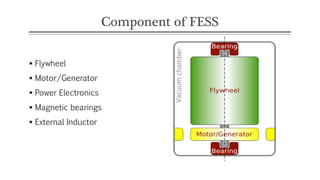
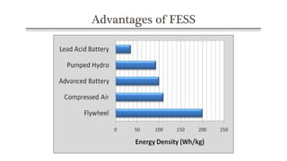
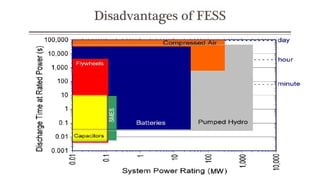
Advertisement
Advertisement

More Related Content

Advertisement
Advertisement

Flywheel Energy Storage System

  1. Flywheel Energy Storage System Seminar Links
  2. Introduction  A flywheel, in essence is a mechanical battery - simply a mass rotating about an axis.  Flywheels store energy mechanically in the form of kinetic energy.  They take an electrical input to accelerate the rotor up to speed by using the built-in motor, and return the electrical energy by using this same motor as a generator.  Flywheels are one of the most promising technologies for replacing conventional lead acid batteries as energy storage systems.
  3. Power Converter Controller Stator Motor Generator B E A R I N G S Rotor Block Diagram
  4. Theory of Flywheels  Kinetic energy: where I is the moment of inertia and ω is the angular velocity of a rotating disc.  For a cylinder the moment of inertia is  So the energy is increased if ω increases or if I increases.  I can be increased by locating as much mass on the outside of the disc as possible.  But as the speed increases and more mass is located outside of the disc, mechanical limitations are more important. 21 2 kE I 2 I r dm  41 2 I r a 
  5. Design of flywheel energy storage system  Flywheel systems are best suited for peak output powers of 100 kW to 2 MW and for durations of 12 seconds to 60 seconds .  The energy is present in the flywheel to provide higher power for a shorter duration, the peak output designed for 125 kw for 16 seconds stores enough energy to provide 2 MW for 1 second. Visit www.seminarlinks.blogspot.com to download
  6. Flywheel Energy Storage System
  7. Flywheel Energy Storage System
  8. Component of FESS  Flywheel  Motor/Generator  Power Electronics  Magnetic bearings  External Inductor
  9. Flywheel  Flywheels store energy in a rotating mass of steel of composite material.  Mechanical inertia is the basis of this storage method.  Use of a motor/generator, energy can be cycled (absorbed and then discharged)  Increasing surface speed of flywheel, energy storage capacity (kWh) of unit increased.
  10. Motor/Generator  Permanent Magnet (PM) machines have the most advantages, including higher efficiency and smaller size when compared with other types of motors/generators of the same power rating.  PM also exhibit lower rotor losses and lower winding inductances, which make it more suitable for a vacuum operating environment and the rapid energy transfer of flywheel applications.  The motor/generator is designed to be operated at high speed for minimize system size.
  11. Power Electronics  Flywheel energy storage system is the three-phase IGBT-based PWM inverter/rectifier.  The IGBT is a solid-states device with ability to handle voltages up to 6.7 kV, currents up to 1.2 kA and most important high switching frequencies.
  12. Magnetic Bearings  Magnetic bearings consists of permanent magnets, which support the weight of the Flywheel by repelling forces, and electromagnets are used to stabilize the Flywheel.  The best performing bearing is the high-temperature super-conducting (HTS) magnetic bearing, which can situate the Flywheel automatically without need of electricity or positioning control system.  HTS magnets require cryogenic cooling by liquid nitrogen.
  13. External Inductor  The high-speed PM machines offer low inductances with low number of stator turns and large operating magnetic air gaps .  The low inductances result in High Total Harmonic Distortion (THD) which increases the machine power losses and temperature.  Using an external inductor in series with the machine in charging mode is necessary to reduce the THD and bring it within an accepted range.
  14. Working of a flywheel energy storage system Its work in three mode:-  Charging mode  Stand by mode  Discharging mode
  15. Circuit diagram of FESS
  16. Applications of FESS  Load Following for Distributed Generation  Power Quality/UPS  Industrial Pulsed Power  Light rail power  Flywheel in distribution network  Hybrid and electric vehicles
  17. Advantages of FESS  High power density.  High energy density.  The lifetime of the flywheel is almost independent of the depth of the charge and discharge cycle.  No periodic maintenance is required.  Short recharge time.  Flywheel systems are not sensitive to temperature since they are operating in a vacuum containment
  18. Advantages of FESS
  19. Disadvantages of FESS  Complexity of durable and low loss bearings  Mechanical stress and fatigue limits  Material limits at around 700M/sec tip speed  Potentially hazardous failure modes  Short discharge time Visit www.seminarlinks.blogspot.com to download
  20. Disadvantages of FESS
  21. Future work in FESS  Advanced flywheel system rotate above 20,000 rpm in vacuum enclosure made from high strength carbon composite filament will be very efficient.  The flywheels are not the primary source of power generation.  Rather, when there is too much power on the grid, it is shunted to the flywheel facility and used to set the flywheels in motion.  Then, when the power is needed a few seconds or minutes later, the momentum of the flywheels is used to generate power back into the grid.
  22. Conclusions  The state of charge can easily be measured, since it is given by the rotational velocity  The fast rotation of Flywheel rotors is suitable for direct generation of high voltage.  Environmental friendly materials, low environmental impact.
  23. Thank You Visit www.seminarlinks.blogspot.com to download
Advertisement