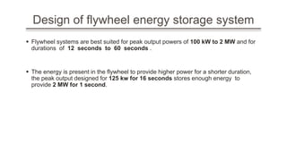
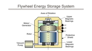
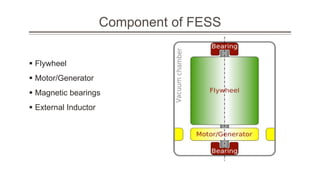
Flywheel Energy
Storage System
Introduction
 A flywheel, in essence is a mechanical battery - simply a mass rotating
about an axis.
 Flywheels store energy mechanically in the form of kinetic energy.
 They take an electrical input to accelerate the rotor up to speed by using
the built-in motor, and return the electrical energy by using this same
motor as a generator.
 Flywheels are one of the most promising technologies for replacing
conventional lead acid batteries as energy storage systems.
Design of flywheel energy storage system
 Flywheel systems are best suited for peak output powers of 100 kW to 2 MW and for
durations of 12 seconds to 60 seconds .
 The energy is present in the flywheel to provide higher power for a shorter duration,
the peak output designed for 125 kw for 16 seconds stores enough energy to
provide 2 MW for 1 second.
Flywheel Energy Storage System
Component of FESS
 Flywheel
 Motor/Generator
 Magnetic bearings
 External Inductor
Flywheel
 Flywheels store energy in a rotating mass of steel of composite material.
 Mechanical inertia is the basis of this storage method.
 Use of a motor/generator, energy can be cycled (absorbed and then
discharged)
 Increasing surface speed of flywheel, energy storage capacity (kWh) of
unit increased.
Motor/Generator
 Permanent Magnet (PM) machines have the most advantages,
including higher efficiency and smaller size when compared with other
types of motors/generators of the same power rating.
 PM also exhibit lower rotor losses and lower winding inductances,
which make it more suitable for a vacuum operating environment
and the rapid energy transfer of flywheel applications.
 The motor/generator is designed to be operated at high speed for
minimize system size.
Magnetic Bearings
 Magnetic bearings consists of permanent magnets, which support the
weight of the Flywheel by repelling forces, and electromagnets are used
to stabilize the Flywheel.
 The best performing bearing is the high-temperature super-conducting
(HTS) magnetic bearing, which can situate the Flywheel automatically
without need of electricity or positioning control system.
 HTS magnets require cryogenic cooling by liquid nitrogen.
External Inductor
 The high-speed PM machines offer low inductances with low
number of stator turns and large operating magnetic air gaps .
 The low inductances result in High Total Harmonic Distortion
(THD) which increases the machine power losses and temperature.
 Using an external inductor in series with the machine in charging
mode is necessary to reduce the THD and bring it within an accepted
range.
Working of a flywheel energy storage system
Its work in three mode:-
 Charging mode
 Stand by mode
 Discharging mode
Applications of FESS
 Power Quality/UPS
 Industrial Pulsed Power
 Light rail power
 Flywheel in distribution network
 Hybrid and electric vehicles
Advantages of FESS
 High power density.
 High energy density.
 The lifetime of the flywheel is almost independent of the depth of the charge and
discharge cycle.
 No periodic maintenance is required.
 Short recharge time.
 Flywheel systems are not sensitive to temperature since they are operating in a
vacuum containment
Disadvantages of FESS
 Complexity of durable and low loss bearings
 Mechanical stress and fatigue limits
 Material limits at around 700M/sec tip speed
 Potentially hazardous failure modes
 Short discharge time
Future work in FESS
 Advanced flywheel system rotate above 20,000 rpm in vacuum enclosure made from
high strength carbon composite filament will be very efficient.
 The flywheels are not the primary source of power generation.
 Rather, when there is too much power on the grid, it is shunted to the flywheel facility
and used to set the flywheels in motion.
 Then, when the power is needed a few seconds or minutes later, the momentum of the
flywheels is used to generate power back into the grid.
Conclusions
 The state of charge can easily be measured, since it is given by the rotational velocity
 The fast rotation of Flywheel rotors is suitable for direct generation of high voltage.
 Environmental friendly materials, low environmental impact.
Thank
You

_Flywheel Energy Storage System.pptx

  • 1.
  • 2.
    Introduction  A flywheel,in essence is a mechanical battery - simply a mass rotating about an axis.  Flywheels store energy mechanically in the form of kinetic energy.  They take an electrical input to accelerate the rotor up to speed by using the built-in motor, and return the electrical energy by using this same motor as a generator.  Flywheels are one of the most promising technologies for replacing conventional lead acid batteries as energy storage systems.
  • 3.
    Design of flywheelenergy storage system  Flywheel systems are best suited for peak output powers of 100 kW to 2 MW and for durations of 12 seconds to 60 seconds .  The energy is present in the flywheel to provide higher power for a shorter duration, the peak output designed for 125 kw for 16 seconds stores enough energy to provide 2 MW for 1 second.
  • 4.
  • 5.
    Component of FESS Flywheel  Motor/Generator  Magnetic bearings  External Inductor
  • 6.
    Flywheel  Flywheels storeenergy in a rotating mass of steel of composite material.  Mechanical inertia is the basis of this storage method.  Use of a motor/generator, energy can be cycled (absorbed and then discharged)  Increasing surface speed of flywheel, energy storage capacity (kWh) of unit increased.
  • 7.
    Motor/Generator  Permanent Magnet(PM) machines have the most advantages, including higher efficiency and smaller size when compared with other types of motors/generators of the same power rating.  PM also exhibit lower rotor losses and lower winding inductances, which make it more suitable for a vacuum operating environment and the rapid energy transfer of flywheel applications.  The motor/generator is designed to be operated at high speed for minimize system size.
  • 8.
    Magnetic Bearings  Magneticbearings consists of permanent magnets, which support the weight of the Flywheel by repelling forces, and electromagnets are used to stabilize the Flywheel.  The best performing bearing is the high-temperature super-conducting (HTS) magnetic bearing, which can situate the Flywheel automatically without need of electricity or positioning control system.  HTS magnets require cryogenic cooling by liquid nitrogen.
  • 9.
    External Inductor  Thehigh-speed PM machines offer low inductances with low number of stator turns and large operating magnetic air gaps .  The low inductances result in High Total Harmonic Distortion (THD) which increases the machine power losses and temperature.  Using an external inductor in series with the machine in charging mode is necessary to reduce the THD and bring it within an accepted range.
  • 10.
    Working of aflywheel energy storage system Its work in three mode:-  Charging mode  Stand by mode  Discharging mode
  • 11.
    Applications of FESS Power Quality/UPS  Industrial Pulsed Power  Light rail power  Flywheel in distribution network  Hybrid and electric vehicles
  • 12.
    Advantages of FESS High power density.  High energy density.  The lifetime of the flywheel is almost independent of the depth of the charge and discharge cycle.  No periodic maintenance is required.  Short recharge time.  Flywheel systems are not sensitive to temperature since they are operating in a vacuum containment
  • 13.
    Disadvantages of FESS Complexity of durable and low loss bearings  Mechanical stress and fatigue limits  Material limits at around 700M/sec tip speed  Potentially hazardous failure modes  Short discharge time
  • 14.
    Future work inFESS  Advanced flywheel system rotate above 20,000 rpm in vacuum enclosure made from high strength carbon composite filament will be very efficient.  The flywheels are not the primary source of power generation.  Rather, when there is too much power on the grid, it is shunted to the flywheel facility and used to set the flywheels in motion.  Then, when the power is needed a few seconds or minutes later, the momentum of the flywheels is used to generate power back into the grid.
  • 15.
    Conclusions  The stateof charge can easily be measured, since it is given by the rotational velocity  The fast rotation of Flywheel rotors is suitable for direct generation of high voltage.  Environmental friendly materials, low environmental impact.
  • 16.