Download to read offline
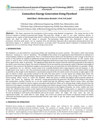
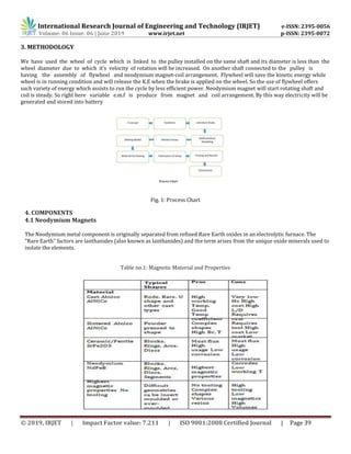
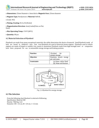

This document describes a system for generating electricity using a flywheel. The system uses a flywheel attached to a shaft that is rotated by a low-power motor. Magnets attached to the flywheel induce a voltage in coils as the flywheel spins. This generates electricity that is stored in a battery. When the motor is braked, the kinetic energy of the spinning flywheel is released and used to continue powering the system. The flywheel is made of a high-strength material like steel and spins at high speeds to store significant amounts of rotational energy. This stored energy allows the system to generate electricity even after the initial motor input is stopped.