Presentation on
Datapath
Datapath
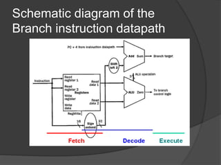
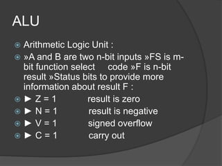
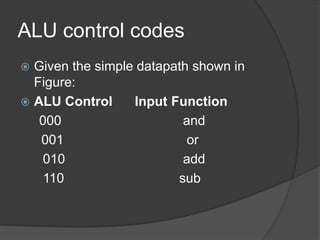
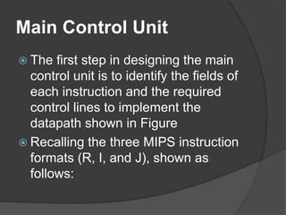
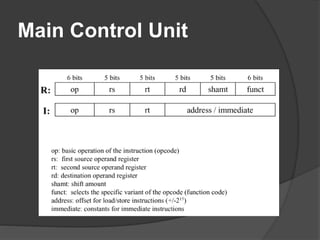
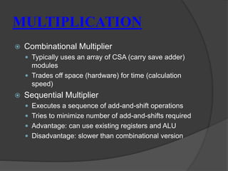
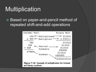
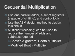
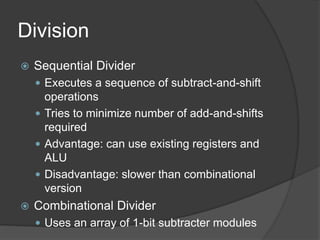
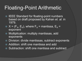
 A datapath is a collection of functional
units, such as arithmetic logic
units or multipliers, that perform data
processing operations, registers, and
buses. Along with the control unit it
composes the central processing unit
(CPU).
General discipline for datapath
design
 (1) determine the instruction classes and
formats in the ISA,
 (2) design datapath components and
interconnections for each instruction
class or format, and
 (3) compose the datapath segments
designed in Step 2) to yield a composite
datapath
Increment program counter
Load/Store Datapath
 Load/Store Datapath: The load/store
datapath uses instructions
where offset denotes a memory address
offset applied to the base address in
register .
 Fetch instruction from instruction memory
and increment PC
 Read register value from the register file
 Result from ALU is applied as an address to
the data memory
Branch/Jump Datapath
 Branch/Jump Datapath: The branch
datapath (jump is an unconditional
branch) uses instructions such as
offset, where offset is a 16-bit offset for
computing the branch target address via
PC-relative addressing.
 Register Access takes input from the
register file, to implement the instruction
fetch or data fetch step of the fetch-
decode-execute cycle.
Schematic diagram of the
Branch instruction datapath
ALU
 Arithmetic Logic Unit :
 »A and B are two n-bit inputs »FS is m-
bit function select code »F is n-bit
result »Status bits to provide more
information about result F :
 ► Z = 1 result is zero
 ► N = 1 result is negative
 ► V = 1 signed overflow
 ► C = 1 carry out
ALU control codes
 Given the simple datapath shown in
Figure:
 ALU Control Input Function
000 and
001 or
010 add
110 sub
Main Control Unit
 The first step in designing the main
control unit is to identify the fields of
each instruction and the required
control lines to implement the
datapath shown in Figure
 Recalling the three MIPS instruction
formats (R, I, and J), shown as
follows:
Main Control Unit
MULTIPLICATION
Multiplication is a less common operation than
addition but is still essential for
microprocessors, digital signal processors and
graphics engines. Multiplications algorithm is
used to illustrate methods of designing different
cells so that they fit into larger structures. The
most common form of multiplication consists
of forming the product of two unsigned
(positive) binary numbers. This can be achieved
through the traditional technique taught in
primary school, simplified to base 2.
MULTIPLICATION
 Combinational Multiplier
 Typically uses an array of CSA (carry save adder)
modules
 Trades off space (hardware) for time (calculation
speed)
 Sequential Multiplier
 Executes a sequence of add-and-shift operations
 Tries to minimize number of add-and-shifts required
 Advantage: can use existing registers and ALU
 Disadvantage: slower than combinational version
Multiplication
 Based on paper-and-pencil method of
repeated shift-and-add operations
Sequential Multiplication
 Use one parallel adder, a set of registers
(capable of shifting), and control logic
 Use the ASM design method to design
this circuit
 Multiplier “recoding” can be used to
reduce the number of adds and
subtracts required
 Booth’s Algorithm, Booth Multiplier
 Modified Booth Multiplier
Division
 Sequential Divider
 Executes a sequence of subtract-and-shift
operations
 Tries to minimize number of add-and-shifts
required
 Advantage: can use existing registers and
ALU
 Disadvantage: slower than combinational
version
 Combinational Divider
 Uses an array of 1-bit subtracter modules
Floating-Point Arithmetic
 IEEE Standard for floating-point numbers
based on draft proposed by Kahan et. al. in
1979.
 X = (FX, EX), where FX = mantissa, EX =
exponent
 Multiplication: multiply mantissas, add
exponents
 Division: divide mantissas, subtract exponents
 Addition: shift one mantissa and add
 Subtraction: shift one mantissa and subtract
2’s COMPLEMENT ARRAY
MULTIPLICATION
 Multiplication of 2’s complement numbers are
seem more difficult because some partial
products are negative and must be subtracted. We
know that the most significant bit of a 2’s
complement number has a negative weight.
Thank You

Datapath Design of Computer Architecture

  • 1.
  • 2.
    Datapath  A datapathis a collection of functional units, such as arithmetic logic units or multipliers, that perform data processing operations, registers, and buses. Along with the control unit it composes the central processing unit (CPU).
  • 3.
    General discipline fordatapath design  (1) determine the instruction classes and formats in the ISA,  (2) design datapath components and interconnections for each instruction class or format, and  (3) compose the datapath segments designed in Step 2) to yield a composite datapath
  • 4.
  • 5.
    Load/Store Datapath  Load/StoreDatapath: The load/store datapath uses instructions where offset denotes a memory address offset applied to the base address in register .  Fetch instruction from instruction memory and increment PC  Read register value from the register file  Result from ALU is applied as an address to the data memory
  • 6.
    Branch/Jump Datapath  Branch/JumpDatapath: The branch datapath (jump is an unconditional branch) uses instructions such as offset, where offset is a 16-bit offset for computing the branch target address via PC-relative addressing.  Register Access takes input from the register file, to implement the instruction fetch or data fetch step of the fetch- decode-execute cycle.
  • 7.
    Schematic diagram ofthe Branch instruction datapath
  • 8.
    ALU  Arithmetic LogicUnit :  »A and B are two n-bit inputs »FS is m- bit function select code »F is n-bit result »Status bits to provide more information about result F :  ► Z = 1 result is zero  ► N = 1 result is negative  ► V = 1 signed overflow  ► C = 1 carry out
  • 9.
    ALU control codes Given the simple datapath shown in Figure:  ALU Control Input Function 000 and 001 or 010 add 110 sub
  • 10.
    Main Control Unit The first step in designing the main control unit is to identify the fields of each instruction and the required control lines to implement the datapath shown in Figure  Recalling the three MIPS instruction formats (R, I, and J), shown as follows:
  • 11.
  • 12.
    MULTIPLICATION Multiplication is aless common operation than addition but is still essential for microprocessors, digital signal processors and graphics engines. Multiplications algorithm is used to illustrate methods of designing different cells so that they fit into larger structures. The most common form of multiplication consists of forming the product of two unsigned (positive) binary numbers. This can be achieved through the traditional technique taught in primary school, simplified to base 2.
  • 13.
    MULTIPLICATION  Combinational Multiplier Typically uses an array of CSA (carry save adder) modules  Trades off space (hardware) for time (calculation speed)  Sequential Multiplier  Executes a sequence of add-and-shift operations  Tries to minimize number of add-and-shifts required  Advantage: can use existing registers and ALU  Disadvantage: slower than combinational version
  • 14.
    Multiplication  Based onpaper-and-pencil method of repeated shift-and-add operations
  • 15.
    Sequential Multiplication  Useone parallel adder, a set of registers (capable of shifting), and control logic  Use the ASM design method to design this circuit  Multiplier “recoding” can be used to reduce the number of adds and subtracts required  Booth’s Algorithm, Booth Multiplier  Modified Booth Multiplier
  • 16.
    Division  Sequential Divider Executes a sequence of subtract-and-shift operations  Tries to minimize number of add-and-shifts required  Advantage: can use existing registers and ALU  Disadvantage: slower than combinational version  Combinational Divider  Uses an array of 1-bit subtracter modules
  • 17.
    Floating-Point Arithmetic  IEEEStandard for floating-point numbers based on draft proposed by Kahan et. al. in 1979.  X = (FX, EX), where FX = mantissa, EX = exponent  Multiplication: multiply mantissas, add exponents  Division: divide mantissas, subtract exponents  Addition: shift one mantissa and add  Subtraction: shift one mantissa and subtract
  • 18.
    2’s COMPLEMENT ARRAY MULTIPLICATION Multiplication of 2’s complement numbers are seem more difficult because some partial products are negative and must be subtracted. We know that the most significant bit of a 2’s complement number has a negative weight.
  • 19.