Downloaded 236 times
![Fetch
Fetch: Fetch next instruction into IR
(Instruction Register).
Assume each word is 4 bytes and each
instruction is stored in a word, and that
the memory is byte addressable.
PC (Program Counter) contains address
of next instruction.
IR [[PC]]
PC [PC] + 4](https://image.slidesharecdn.com/mypptbasicprocessingunit-130130022041-phpapp02/85/Basic-Processing-Unit-5-320.jpg)


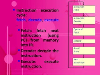
![Arithmetic/Logic Operation
Internal
processor bus
ALU: Performs Riin
Yin
arithmetic and logic X
X
operations on its A
Ri
Y
and B inputs. Constant 4
X
To perform
Riout
Select MUX
R3 [R1] + [R2]:
1. R1out, Yin A B
ALU
2. R2out, SelectY, A
dd, Zin Zin X
3. Zout, R3in
Z
X
Zout](https://image.slidesharecdn.com/mypptbasicprocessingunit-130130022041-phpapp02/85/Basic-Processing-Unit-10-320.jpg)

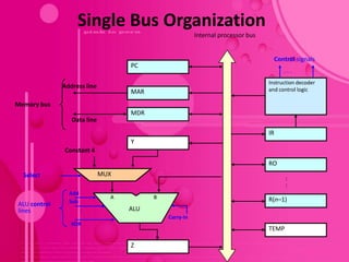
![Reading a Word from Memory
Move R3, (R2) /* R2 [[R1]]
1. MAR [R2]
2. Start a Read operation on the memory bus
3. Wait for the MFC response from the memory
4. Load MDR from the memory bus
5. R3 [MDR]
MDR has four control signals: MDRin, MDRout, MDRinE and
MDRoutE
Memory-bus data Internal processor
lines bus
MOVE R3, (R2) MDRinE MDRin
Control Signals… X X
R2out, MARin, Read. MDR
WMFC
MDRout, R3in X X
MDRoutE MDRout](https://image.slidesharecdn.com/mypptbasicprocessingunit-130130022041-phpapp02/85/Basic-Processing-Unit-12-320.jpg)
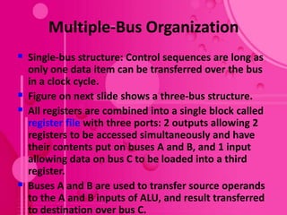
![Reading a Word from Memory (2)
Move (R1), R2 /* R2 [[R1]]
Sequence of control steps:
1. R1out, MARin, Read
2. R2out, MDRinE, WMFC
3. MDRout, R2in
WMFC: Wait for arrival of MFC (Memory-Function-
Completed) signal.
MFC: To accommodate variability in response time, the
processor waits until it receives an indication that the
Read/Write operation has been completed. The
addressed device sets MFC to 1 to indicate this.](https://image.slidesharecdn.com/mypptbasicprocessingunit-130130022041-phpapp02/85/Basic-Processing-Unit-13-320.jpg)
![Storing a Word in Memory
Move R2, (R1) /* [R1] [R2]
Sequence of control steps:
1.R1out, MARin
2.R2out, MDRin, Write
3.MDRoutE, WMFC
4.R1in.](https://image.slidesharecdn.com/mypptbasicprocessingunit-130130022041-phpapp02/85/Basic-Processing-Unit-14-320.jpg)
![Example 2
• MOVE (R2), R1.
• MAR [R2] R2out, MARin,
R1out, MDRin, Write
• MDR [R1]
WMFC
MDRout, R2in](https://image.slidesharecdn.com/mypptbasicprocessingunit-130130022041-phpapp02/85/Basic-Processing-Unit-15-320.jpg)
![Executing a Complete Instruction
Add (R3), R1 /* R1 [R1] + [[R3]]
Adds the contents of a memory location pointed
to by R3 to register R1.
Sequence of control steps: Steps 1 – 3:
1. PCout, MARin, Read, Select4, Add, ZinInstruction
fetch
2. Zout, PCin, Yin, WMFC
3. MDRout, IRin
4. R3out, MARin, Read
5. R1out, Yin, WMFC
6. MDRout, SelectY, Add, Zin
7. Z , R1 , End](https://image.slidesharecdn.com/mypptbasicprocessingunit-130130022041-phpapp02/85/Basic-Processing-Unit-16-320.jpg)
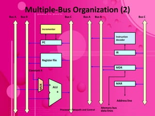
![Multiple-Bus Organization (3)
For the ALU, R=A (or R=B) means that its A (or B)
input is passed unmodified to bus C.
Add R4, R5, R6 /* R6 [R4] + [R5]
Adds the contents of R4 and R5 to R6.
Sequence of control steps:
1. PCout, R=B, MARin, Read, IncPC
2. WMFC
3. MDRoutB, R=B, IRin
4. R4outA, R5outB, SelectA, Add, R6in, End](https://image.slidesharecdn.com/mypptbasicprocessingunit-130130022041-phpapp02/85/Basic-Processing-Unit-19-320.jpg)

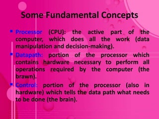
The document discusses the basic processing unit of a computer. It describes the objective, fundamental concepts, and components of a processor including the datapath, control unit, instruction cycle of fetch, decode, and execute. It explains the concepts of registers, arithmetic logic unit (ALU), and how instructions are executed through register transfers, arithmetic/logic operations, and reading/writing from memory. It also compares single-bus and multiple-bus processor organizations.