Download as PDF, PPTX
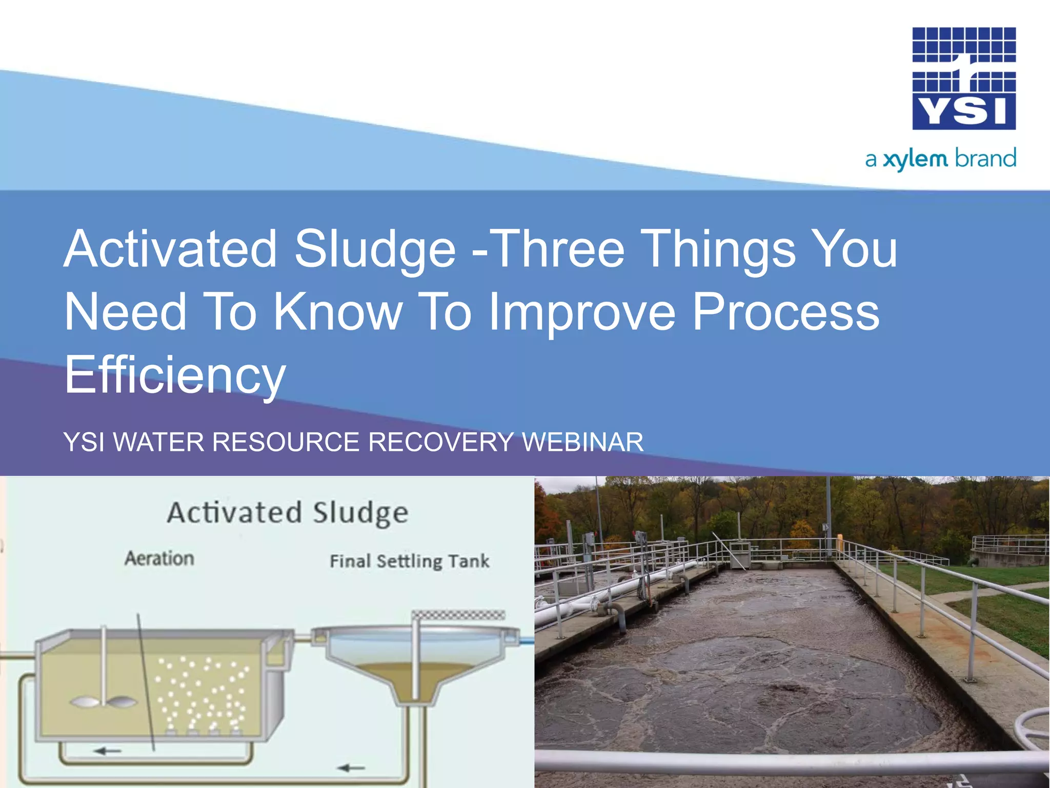


The document discusses the activated sludge process in wastewater treatment, emphasizing process control through aeration, sludge wasting, and recirculation for improved efficiency. Key concepts include biological treatment parameters such as dissolved oxygen levels, nitrification, denitrification, and the importance of trained personnel. It highlights methods for measuring and controlling various factors to ensure effective biomass management and wastewater treatment outcomes.